
User Guide
Page 6
... of each server system are three versions of this server system: the Intel® Server Systems SR2520SAX/ SR2520SAXS and SR2520SAXR/SR2520SAXSR (SAS/SATA versions) and the Intel® Server System SR2520SAF/SR2520SAFR (SATA only version). There are listed below. Intel® Server System SR2520SAX/SR2520SAXR Contents Your Intel® Server System SR2520SAX/SR2520SAXR ships with the following items: • Intel® Server Board S5000VSA (SATA SKU), installed in the server system • One...
... of each server system are three versions of this server system: the Intel® Server Systems SR2520SAX/ SR2520SAXS and SR2520SAXR/SR2520SAXSR (SAS/SATA versions) and the Intel® Server System SR2520SAF/SR2520SAFR (SATA only version). There are listed below. Intel® Server System SR2520SAX/SR2520SAXR Contents Your Intel® Server System SR2520SAX/SR2520SAXR ships with the following items: • Intel® Server Board S5000VSA (SATA SKU), installed in the server system • One...

User Guide
Page 14
... Add-in Card 49 Installing and Removing the Server Board 50 Installing the Server Board 50 Removing the Server Board 51 Replacing the Backup Battery 52 Replacing the Redundant Power Supply (SR2520SAX/SR2520SAXS and SR2520SAXR/ SR2520SAXSR) ...54 Replacing the Fixed Power Supply...System Fan ...60 Installing and Removing the Rack Handles 62 Installing the Rack Handles 62 Removing the Rack Handles 63 Chapter 4: Server Utilities 65 Using the BIOS Setup Utility 65 Starting Setup ...65 If You Cannot Access Setup 65 Setup Menus ...65 Upgrading the BIOS ...67 xiv Intel® Server System...
... Add-in Card 49 Installing and Removing the Server Board 50 Installing the Server Board 50 Removing the Server Board 51 Replacing the Backup Battery 52 Replacing the Redundant Power Supply (SR2520SAX/SR2520SAXS and SR2520SAXR/ SR2520SAXSR) ...54 Replacing the Fixed Power Supply...System Fan ...60 Installing and Removing the Rack Handles 62 Installing the Rack Handles 62 Removing the Rack Handles 63 Chapter 4: Server Utilities 65 Using the BIOS Setup Utility 65 Starting Setup ...65 If You Cannot Access Setup 65 Setup Menus ...65 Upgrading the BIOS ...67 xiv Intel® Server System...

User Guide
Page 15
...(RoHS) Compliance 92 End-of the Operating System 99 Intel® Server System SR2520SA User's Guide xv Preparing for Intel® Chassis Subassembly Products 93 Appendix F: Troubleshooting 97 Resetting the System ...97 Problems following Initial System Installation 98 First Steps Checklist ...98 Hardware ... 72 600W Single Power Supply Input Voltages 73 600W Single Power Supply Output Voltages 73 System Environmental Specifications 74 Appendix B: LED Decoder (SR2520SAX /SR2520SAXS and SR2520SAXR/ SR2520SAXSR Only 75 Appendix C: Getting Help 81 World Wide Web ...81 Telephone ...81...
...(RoHS) Compliance 92 End-of the Operating System 99 Intel® Server System SR2520SA User's Guide xv Preparing for Intel® Chassis Subassembly Products 93 Appendix F: Troubleshooting 97 Resetting the System ...97 Problems following Initial System Installation 98 First Steps Checklist ...98 Hardware ... 72 600W Single Power Supply Input Voltages 73 600W Single Power Supply Output Voltages 73 System Environmental Specifications 74 Appendix B: LED Decoder (SR2520SAX /SR2520SAXS and SR2520SAXR/ SR2520SAXSR Only 75 Appendix C: Getting Help 81 World Wide Web ...81 Telephone ...81...

User Guide
Page 19
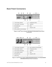
... 28 Figure 19. Installing the Processor 34 Figure 24. Removing Optical Drive Knockout 45 Intel® Server System SR2520SA User's Guide xix Light Guided Diagnostic LEDs (SR2520SAX/SR2520SAXS and SR2520SAXR/ SR2520SAXSR)...12 Figure 8. Intel® Server System SR2520SAF/SR2520SAFR Back Panel Connectors 13 Figure 9. Lifting the Processor Socket Handle 34 Figure 23. Removing the Socket Cover 35...
... 28 Figure 19. Installing the Processor 34 Figure 24. Removing Optical Drive Knockout 45 Intel® Server System SR2520SA User's Guide xix Light Guided Diagnostic LEDs (SR2520SAX/SR2520SAXS and SR2520SAXR/ SR2520SAXSR)...12 Figure 8. Intel® Server System SR2520SAF/SR2520SAFR Back Panel Connectors 13 Figure 9. Lifting the Processor Socket Handle 34 Figure 23. Removing the Socket Cover 35...

User Guide
Page 20
...72 xx Intel® Server System SR2520SA User's Guide Replacing the Backup Battery 53 Figure 42. Removing the Front Panel Board 58 Figure 47. Clear Password Jumper 68 Figure 57. Installing Power Supply Module into the Server System (SR2520SAX/SR2520SAXS and SR2520SAXR/SR2520SAXSR 55... Figure 44. Removing Drive Bracket and Optical Drive from the Server System (SR2520SAX/ SR2520SAXS and SR2520SAXR/SR2520SAXSR 54 Figure 43. Removing the Rack Handle 64 ...
...72 xx Intel® Server System SR2520SA User's Guide Replacing the Backup Battery 53 Figure 42. Removing the Front Panel Board 58 Figure 47. Clear Password Jumper 68 Figure 57. Installing Power Supply Module into the Server System (SR2520SAX/SR2520SAXS and SR2520SAXR/SR2520SAXSR 55... Figure 44. Removing Drive Bracket and Optical Drive from the Server System (SR2520SAX/ SR2520SAXS and SR2520SAXR/SR2520SAXSR 54 Figure 43. Removing the Rack Handle 64 ...

User Guide
Page 26
...; Xeon® processors 5000 or 5100 sequence with a 1066- Up to 8 GB of total system memory) Intel® 5000V chipset, consisting of the server system. Product codes SR2520SAFR, SR2520SAXR, and SR2520SAXSR only. Intel® Server System SR2520SA Feature Summary Feature Dimensions Server Board Processor Memory Chipset Description • 3.44 inches (87.30 mm) high • 16.930 inches (430...
...; Xeon® processors 5000 or 5100 sequence with a 1066- Up to 8 GB of total system memory) Intel® 5000V chipset, consisting of the server system. Product codes SR2520SAFR, SR2520SAXR, and SR2520SAXSR only. Intel® Server System SR2520SA Feature Summary Feature Dimensions Server Board Processor Memory Chipset Description • 3.44 inches (87.30 mm) high • 16.930 inches (430...

User Guide
Page 27
... requires an AXXRAKSW5 RAID key. • SR2520SAXS/SR2520SAXSR: Four SAS and two SATA connectors with 16 MB DDR SDRAM Intel® 82563EB dual port controller for 10/100/1000 Mbit/sec Ethernet LAN connectivity • One 32...SR2520SAXR/SR2520SAXSR: Six Serial ATA connectors with embedded RAID 0/1/10 support for IDE optical drive • PCI riser card bracket • Standard control panel With standard control panel: • NIC1 Activity • NIC2 Activity • Power / Sleep • System Status • System Identification • Hard Drive Activity Intel® Server System...
... requires an AXXRAKSW5 RAID key. • SR2520SAXS/SR2520SAXSR: Four SAS and two SATA connectors with 16 MB DDR SDRAM Intel® 82563EB dual port controller for 10/100/1000 Mbit/sec Ethernet LAN connectivity • One 32...SR2520SAXR/SR2520SAXSR: Six Serial ATA connectors with embedded RAID 0/1/10 support for IDE optical drive • PCI riser card bracket • Standard control panel With standard control panel: • NIC1 Activity • NIC2 Activity • Power / Sleep • System Status • System Identification • Hard Drive Activity Intel® Server System...
User Guide
Page 28
Intel® Server System SR2520SA Feature Summary Feature Power Supply Fans System Management Description • Single 600 W power supply module (SR2520SAF) • Redundant 600 W power supply modules (SR2520SAX/ SR2520SAXS and SR2520SAXR/SR2520SAXSR) • Three system cooling fans • Two non-redundant fans in power supply Intel® System Management Software 6 Intel® Server System SR2520SA User's Guide Table 2.
Intel® Server System SR2520SA Feature Summary Feature Power Supply Fans System Management Description • Single 600 W power supply module (SR2520SAF) • Redundant 600 W power supply modules (SR2520SAX/ SR2520SAXS and SR2520SAXR/SR2520SAXSR) • Three system cooling fans • Two non-redundant fans in power supply Intel® System Management Software 6 Intel® Server System SR2520SA User's Guide Table 2.
User Guide
Page 29
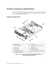
... J. ChassisComponents (SR2520SAX/SR2520SAXS and SR2520SAXR/SR2520SAXSR) Intel® Server System SR2520SA User's Guide 7 Rack Handles B. Slimline Floppy Drive K. Hard Drive Bays (drives not included) Figure 2. System Cooling Fans C. Hot-Swap Power Supplies F. Control Panel (standard control panel shown) I H F G A AF001442 A. Internal Components D C B E A K J I . CPU Air Duct D. Server Board E. If you are near the system, you identify the components of...
... J. ChassisComponents (SR2520SAX/SR2520SAXS and SR2520SAXR/SR2520SAXSR) Intel® Server System SR2520SA User's Guide 7 Rack Handles B. Slimline Floppy Drive K. Hard Drive Bays (drives not included) Figure 2. System Cooling Fans C. Hot-Swap Power Supplies F. Control Panel (standard control panel shown) I H F G A AF001442 A. Internal Components D C B E A K J I . CPU Air Duct D. Server Board E. If you are near the system, you identify the components of...

User Guide
Page 31
.... PCI-X* 64/133 Slot 4 F. Processor 1 Socket R. SAS SGPIO (SR2520SAX/ SR2520SAXS and SR2520SAXR/SR2520SAXSR only) DD. System Fan 2 GG. SATA 5/SAS 3 Connector Intel® Server System SR2520SA User's Guide 9 PCIe* x4 Slot 3 E. SAS_SES2 (SR2520SAX/ SR2520SAXS and SR2520SAXR/SR2520SAXSR only) CC. SATA 4/SAS 2 Connector C. Auxiliary Signal Connector P. System Fan 5 N. SATA SGPIO II. IDE Connector AA. PCI-X 64/100 Slot...
.... PCI-X* 64/133 Slot 4 F. Processor 1 Socket R. SAS SGPIO (SR2520SAX/ SR2520SAXS and SR2520SAXR/SR2520SAXSR only) DD. System Fan 2 GG. SATA 5/SAS 3 Connector Intel® Server System SR2520SA User's Guide 9 PCIe* x4 Slot 3 E. SAS_SES2 (SR2520SAX/ SR2520SAXS and SR2520SAXR/SR2520SAXSR only) CC. SATA 4/SAS 2 Connector C. Auxiliary Signal Connector P. System Fan 5 N. SATA SGPIO II. IDE Connector AA. PCI-X 64/100 Slot...

User Guide
Page 32
...-X* 64/133 Slot 4 PP. PCIe* x4 Slot 3 OO. USB 6 (SR2520SAX/ SR2520SAXS and SR2520SAXR/SR2520SAXSR only) TT. SATA RAID 5 Key UU. BIOS Select Jumper CMOS CLR PASSWORD CLR Default Default 2 2 CLEAR CLEAR 3 CMOS 3 PASSWORD J1J1 J1J2 AF000187 10 Intel® Server System SR2520SA User's Guide Front Panel Header RR. Speaker BIOS Select Force Lower 2 Bank...
...-X* 64/133 Slot 4 PP. PCIe* x4 Slot 3 OO. USB 6 (SR2520SAX/ SR2520SAXS and SR2520SAXR/SR2520SAXSR only) TT. SATA RAID 5 Key UU. BIOS Select Jumper CMOS CLR PASSWORD CLR Default Default 2 2 CLEAR CLEAR 3 CMOS 3 PASSWORD J1J1 J1J2 AF000187 10 Intel® Server System SR2520SA User's Guide Front Panel Header RR. Speaker BIOS Select Force Lower 2 Bank...
User Guide
Page 34
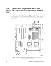
A C B D E F G I J K LMNO P H Y Q R S XW V U T AF000188 Figure 7. Light Guided Diagnostic LEDs (SR2520SAX/SR2520SAXS and SR2520SAXR/SR2520SAXSR) 12 Intel® Server System SR2520SA User's Guide Except for the ID LED, the status LED, and the 5V standby LED, the LEDs turn on (amber) only if a failure occurs. Intel® Light Guided Diagnostics (SR2520SAX/ SR2520SAXS and SR2520SAXR/SR2520SAXSR Only) The server board contains diagnostic LEDs to help you identify failed and failing components, and to help you identify the server from among several servers.
A C B D E F G I J K LMNO P H Y Q R S XW V U T AF000188 Figure 7. Light Guided Diagnostic LEDs (SR2520SAX/SR2520SAXS and SR2520SAXR/SR2520SAXSR) 12 Intel® Server System SR2520SA User's Guide Except for the ID LED, the status LED, and the 5V standby LED, the LEDs turn on (amber) only if a failure occurs. Intel® Light Guided Diagnostics (SR2520SAX/ SR2520SAXS and SR2520SAXR/SR2520SAXSR Only) The server board contains diagnostic LEDs to help you identify failed and failing components, and to help you identify the server from among several servers.
User Guide
Page 35
... E F G H K J I H G AF001475 A. Power Supply 1 Receptacle B. Back Panel Connectors A BC D E F I AF001441 A. Power Supply 1 Module B. Power Supply 1 Receptacle C. NIC1 and NIC2 (10/100/1000 Mb) F. Diagnostic LEDs Figure 8. Power Supply 1 Module C. Mouse/Keyboard F. NIC1 and NIC2 (10/100/1000 Mb) H. USB Ports J. Intel® Server System SR2520SAX/SR2520SAXS and SR2520SAXR/ SR2520SAXSR Back Panel Connectors Intel® Server System SR2520SA User's Guide 13
... E F G H K J I H G AF001475 A. Power Supply 1 Receptacle B. Back Panel Connectors A BC D E F I AF001441 A. Power Supply 1 Module B. Power Supply 1 Receptacle C. NIC1 and NIC2 (10/100/1000 Mb) F. Diagnostic LEDs Figure 8. Power Supply 1 Module C. Mouse/Keyboard F. NIC1 and NIC2 (10/100/1000 Mb) H. USB Ports J. Intel® Server System SR2520SAX/SR2520SAXS and SR2520SAXR/ SR2520SAXSR Back Panel Connectors Intel® Server System SR2520SA User's Guide 13
User Guide
Page 36
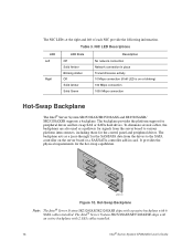
...Description No network connection Network connection in card. Hot-Swap Backplane Note: The Intel® Server System SR2520SAX/SR2520SAXR ships with a passive backplane with 2 SAS cables installed. 14 Intel® Server System SR2520SA User's Guide The backplane provides the platform support for the hot-swap capabilities...100 Mbps connection 1000 Mbps connection Hot-Swap Backplane The Intel® Server System SR2520SAX/SR2520SAXS and SR2520SAXR/ SR2520SAXSR supports a backplane. The NIC LEDs at the right and left LED is on the server board or a SAS/SATA controller add-in place ...
...Description No network connection Network connection in card. Hot-Swap Backplane Note: The Intel® Server System SR2520SAX/SR2520SAXR ships with a passive backplane with 2 SAS cables installed. 14 Intel® Server System SR2520SA User's Guide The backplane provides the platform support for the hot-swap capabilities...100 Mbps connection 1000 Mbps connection Hot-Swap Backplane The Intel® Server System SR2520SAX/SR2520SAXS and SR2520SAXR/ SR2520SAXSR supports a backplane. The NIC LEDs at the right and left LED is on the server board or a SAS/SATA controller add-in place ...

User Guide
Page 37
SATA The Intel® Server Systems SR2520SAF/SR2520SAFR and SR2520SAX/SR2520SAXR provide an embedded SATA controller that is enabled by default. The Legacy and Enhanced modes affect the RAID configuration as RAID." The Intel® Embedded Server RAID Technology II feature provides RAID modes 0, 1, and 10. Intel® Server System SR2520SA User's Guide 15 The BIOS Setup utility provides multiple...
SATA The Intel® Server Systems SR2520SAF/SR2520SAFR and SR2520SAX/SR2520SAXR provide an embedded SATA controller that is enabled by default. The Legacy and Enhanced modes affect the RAID configuration as RAID." The Intel® Embedded Server RAID Technology II feature provides RAID modes 0, 1, and 10. Intel® Server System SR2520SA User's Guide 15 The BIOS Setup utility provides multiple...
User Guide
Page 40
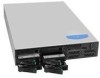
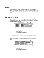
... drive C. Optional Peripherals (SR2520SAX/SR2520SAXS and SR2520SAXR/SR2520SAXSR) The drives must be purchased separately. A. Slimline floppy drive B. drive not included) Figure 13. For instructions on design that allows for maximum airflow through the server chassis. drive not included) Figure 12. Optional Peripherals (SR2520SAF/SR2520SAFR) 18 Intel® Server System SR2520SA User's Guide The drives must...
... drive C. Optional Peripherals (SR2520SAX/SR2520SAXS and SR2520SAXR/SR2520SAXSR) The drives must be purchased separately. A. Slimline floppy drive B. drive not included) Figure 13. For instructions on design that allows for maximum airflow through the server chassis. drive not included) Figure 12. Optional Peripherals (SR2520SAF/SR2520SAFR) 18 Intel® Server System SR2520SA User's Guide The drives must...

User Guide
Page 41
.... In other words, install the first system in the rack into the bottom position of the rack, the second system in the rail kit. Intel® Server System SR2520SA User's Guide 19 Note: The Intel® Server System SR2520SA does not support all SAS or ...Serial ATA (SATA) hard drives. Note: Drives can be specified to mount this server into a rack, Intel recommends you install systems from the bottom, and so on installing hard drives, see "Installing and Removing a Hot-swap Hard Drive (SR2520SAX/SR2520SAXS and SR2520SAXR...
.... In other words, install the first system in the rack into the bottom position of the rack, the second system in the rail kit. Intel® Server System SR2520SA User's Guide 19 Note: The Intel® Server System SR2520SA does not support all SAS or ...Serial ATA (SATA) hard drives. Note: Drives can be specified to mount this server into a rack, Intel recommends you install systems from the bottom, and so on installing hard drives, see "Installing and Removing a Hot-swap Hard Drive (SR2520SAX/SR2520SAXS and SR2520SAXR...

User Guide
Page 59
... carriers. For instructions, see "Installing the Processor". Pull out on the black lever and slide the carrier from the server system. Remove the processor. 11. Remove the front bezel if it is installed. If installing a replacement processor, see "...Disk Drive (SR2520SAX/SR2520SAXS and SR2520SAXR/ SR2520SAXSR) 1. Installing and Removing a Hot-swap Hard Drive (SR2520SAX/SR2520SAXS and SR2520SAXR/ SR2520SAXSR) Up to a list of the hard drive carrier. 3. Note: The server system does not support all hard drives. Intel® Server System SR2520SA User's Guide 37 Raise...
... carriers. For instructions, see "Installing the Processor". Pull out on the black lever and slide the carrier from the server system. Remove the processor. 11. Remove the front bezel if it is installed. If installing a replacement processor, see "...Disk Drive (SR2520SAX/SR2520SAXS and SR2520SAXR/ SR2520SAXSR) 1. Installing and Removing a Hot-swap Hard Drive (SR2520SAX/SR2520SAXS and SR2520SAXR/ SR2520SAXSR) Up to a list of the hard drive carrier. 3. Note: The server system does not support all hard drives. Intel® Server System SR2520SA User's Guide 37 Raise...
User Guide
Page 60
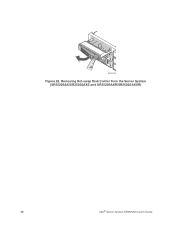
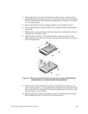
Figure 26. Removing Hot-swap Disk Carrier from the Server System (SR2520SAX/SR2520SAXS and SR2520SAXR/SR2520SAXSR) 38 Intel® Server System SR2520SA User's Guide
Figure 26. Removing Hot-swap Disk Carrier from the Server System (SR2520SAX/SR2520SAXS and SR2520SAXR/SR2520SAXSR) 38 Intel® Server System SR2520SA User's Guide
User Guide
Page 61
... figure below . 5. Do not push on the drive according to the plastic retention device. Remove the hard drive from Drive Carrier (SR2520SAX/ SR2520SAXS and SR2520SAXR/SR2520SAXSR) 9. Intel® Server System SR2520SA User's Guide 39 Two screws are at the front of the retention device or the hard drive. Store the plastic retention device for...
... figure below . 5. Do not push on the drive according to the plastic retention device. Remove the hard drive from Drive Carrier (SR2520SAX/ SR2520SAXS and SR2520SAXR/SR2520SAXSR) 9. Intel® Server System SR2520SA User's Guide 39 Two screws are at the front of the retention device or the hard drive. Store the plastic retention device for...