
User Guide
Page 6
..., in the server system product box • Intel Software CD combo kit, in the server system product box • 3rd party software CD, in the server system product box vi Intel® Server System SR2520SA User's Guide The contents of each server system are three versions of this server system: the Intel® Server Systems SR2520SAX/ SR2520SAXS and SR2520SAXR/SR2520SAXSR (SAS/SATA versions) and the Intel® Server System SR2520SAF/SR2520SAFR (SATA...
..., in the server system product box • Intel Software CD combo kit, in the server system product box • 3rd party software CD, in the server system product box vi Intel® Server System SR2520SA User's Guide The contents of each server system are three versions of this server system: the Intel® Server Systems SR2520SAX/ SR2520SAXS and SR2520SAXR/SR2520SAXSR (SAS/SATA versions) and the Intel® Server System SR2520SAF/SR2520SAFR (SATA...

User Guide
Page 8
...; Server System SR2520SAF/SR2520SAFR Contents Your Intel® Server System SR2520SAF/SR2520SAFR ships with the following items: • Intel® Server Board S5000VSA (4 DIMM SKU), installed in the server system • One 600 W fixed power supply module, installed in the server system • Two 80mm system fans, installed in the server system • One 60mm system fan, installed in the server system • CPU air duct, installed in the server system...
...; Server System SR2520SAF/SR2520SAFR Contents Your Intel® Server System SR2520SAF/SR2520SAFR ships with the following items: • Intel® Server Board S5000VSA (4 DIMM SKU), installed in the server system • One 600 W fixed power supply module, installed in the server system • Two 80mm system fans, installed in the server system • One 60mm system fan, installed in the server system • CPU air duct, installed in the server system...

User Guide
Page 14
... Card 49 Installing and Removing the Server Board 50 Installing the Server Board 50 Removing the Server Board 51 Replacing the Backup Battery 52 Replacing the Redundant Power Supply (SR2520SAX/SR2520SAXS and SR2520SAXR/ SR2520SAXSR) ...54 Replacing the Fixed Power Supply (SR2520SAF/SR2520SAFR 55 Replacing the Front Panel Board 57 Replacing a System Fan ...60 Installing and Removing...
... Card 49 Installing and Removing the Server Board 50 Installing the Server Board 50 Removing the Server Board 51 Replacing the Backup Battery 52 Replacing the Redundant Power Supply (SR2520SAX/SR2520SAXS and SR2520SAXR/ SR2520SAXSR) ...54 Replacing the Fixed Power Supply (SR2520SAF/SR2520SAFR 55 Replacing the Front Panel Board 57 Replacing a System Fan ...60 Installing and Removing...

User Guide
Page 15
... First Steps Checklist ...98 Hardware Diagnostic Testing 99 Verifying Proper Operation of Key System Lights 99 Confirming Loading of the Operating System 99 Intel® Server System SR2520SA User's Guide xv Class A Compliance 86 Certifications / Registrations / Declarations ...Routing (SR2520SAX/SR2520SAXS and SR2520SAXR/SR2520SAXSR 71 Cable Routing (SR2520SAF/SR2520SAFR 72 600W Single Power Supply Input Voltages 73 600W Single Power Supply Output Voltages 73 System Environmental Specifications 74 Appendix B: LED Decoder (SR2520SAX /SR2520SAXS and SR2520SAXR/ SR2520SAXSR Only 75 ...
... First Steps Checklist ...98 Hardware Diagnostic Testing 99 Verifying Proper Operation of Key System Lights 99 Confirming Loading of the Operating System 99 Intel® Server System SR2520SA User's Guide xv Class A Compliance 86 Certifications / Registrations / Declarations ...Routing (SR2520SAX/SR2520SAXS and SR2520SAXR/SR2520SAXSR 71 Cable Routing (SR2520SAF/SR2520SAFR 72 600W Single Power Supply Input Voltages 73 600W Single Power Supply Output Voltages 73 System Environmental Specifications 74 Appendix B: LED Decoder (SR2520SAX /SR2520SAXS and SR2520SAXR/ SR2520SAXSR Only 75 ...

User Guide
Page 19
... Figure 33. Removing Drive Bracket from Drive Carrier (SR2520SAX/SR2520SAXS and SR2520SAXR/SR2520SAXSR 39 Figure 28. Installng Optical Drive into the Server System (SR2520SAX/SR2520SAXS and SR2520SAXR/SR2520SAXSR 40 Figure 29. Intel® Server System SR2520SAF/SR2520SAFR Back Panel Connectors 13 Figure 9. Intel® Server System SR2520SAX/SR2520SAXS and SR2520SAXR/SR2520SAXSR Back Panel Connectors...13 Figure 10. Hot-Swap Backplane 14 Figure...
... Figure 33. Removing Drive Bracket from Drive Carrier (SR2520SAX/SR2520SAXS and SR2520SAXR/SR2520SAXSR 39 Figure 28. Installng Optical Drive into the Server System (SR2520SAX/SR2520SAXS and SR2520SAXR/SR2520SAXSR 40 Figure 29. Intel® Server System SR2520SAF/SR2520SAFR Back Panel Connectors 13 Figure 9. Intel® Server System SR2520SAX/SR2520SAXS and SR2520SAXR/SR2520SAXSR Back Panel Connectors...13 Figure 10. Hot-Swap Backplane 14 Figure...

User Guide
Page 20
... and SR2520SAXR/SR2520SAXSR) 71 Figure 59. Removing Optical Drive from the Front Panel Board 58 Figure 48. Installing Power Supply Module into the Server System 59 Figure 49. Removing the Light Pipes from Drive Bracket 47 Figure 37. Cable Routing (SR2520SAF/SR2520SAFR 72 xx Intel® Server System SR2520SA User's Guide Removing a Fan from the Server System (SR2520SAF/ SR2520SAFR) ...56...
... and SR2520SAXR/SR2520SAXSR) 71 Figure 59. Removing Optical Drive from the Front Panel Board 58 Figure 48. Installing Power Supply Module into the Server System 59 Figure 49. Removing the Light Pipes from Drive Bracket 47 Figure 37. Cable Routing (SR2520SAF/SR2520SAFR 72 xx Intel® Server System SR2520SA User's Guide Removing a Fan from the Server System (SR2520SAF/ SR2520SAFR) ...56...

User Guide
Page 26
...® processors. Product codes SR2520SAFR, SR2520SAXR, and SR2520SAXSR only. Up to 8 GB of total system memory) Intel® 5000V chipset, consisting of the server system. Table 2. Table 2 summarizes the features of : • Intel® 5000V Memory Controller Hub (MCH) • Intel® 6321ESB I/O Controller Hub 4 Intel® Server System SR2520SA User's Guide max chassis weight Intel® Server Board S5000VSA Support for up...
...® processors. Product codes SR2520SAFR, SR2520SAXR, and SR2520SAXSR only. Up to 8 GB of total system memory) Intel® 5000V chipset, consisting of the server system. Table 2. Table 2 summarizes the features of : • Intel® 5000V Memory Controller Hub (MCH) • Intel® 6321ESB I/O Controller Hub 4 Intel® Server System SR2520SA User's Guide max chassis weight Intel® Server Board S5000VSA Support for up...

User Guide
Page 30
Rack Handles B. Server Board E. Power Distribution Board G. Optical Drive Bay J. Hard Drive Bays (drives not included) Figure 3. ChassisComponents (SR2520SAF/SR2520SAFR) 8 Intel® Server System SR2520SA User's Guide Fixed Power Supply F. Slimline Floppy Drive K. Control Panel (standard control panel shown) I H G A F AF001663 A. System Cooling Fans C. CPU Air Duct D. Front Panel H. D C B A E K J I .
Rack Handles B. Server Board E. Power Distribution Board G. Optical Drive Bay J. Hard Drive Bays (drives not included) Figure 3. ChassisComponents (SR2520SAF/SR2520SAFR) 8 Intel® Server System SR2520SA User's Guide Fixed Power Supply F. Slimline Floppy Drive K. Control Panel (standard control panel shown) I H G A F AF001663 A. System Cooling Fans C. CPU Air Duct D. Front Panel H. D C B A E K J I .
User Guide
Page 35
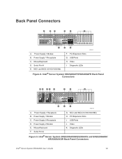
Intel® Server System SR2520SAF/SR2520SAFR Back Panel Connectors AB CD E F G H K J I . NIC1 and NIC2 (10/100/1000 Mb) H. Serial Port A E. Power Supply 1 Receptacle B. Diagnostic LEDs Figure 9. USB Ports H. Diagnostic LEDs Figure 8. Power Supply 1 Module C. Mouse/Keyboard F. USB Ports J. Mouse/Keyboard D. PCI Expansion Slots I AF001441 A. Intel® Server System SR2520SAX/SR2520SAXS and SR2520SAXR/ SR2520SAXSR Back Panel Connectors Intel® Server System SR2520SA User's Guide...
Intel® Server System SR2520SAF/SR2520SAFR Back Panel Connectors AB CD E F G H K J I . NIC1 and NIC2 (10/100/1000 Mb) H. Serial Port A E. Power Supply 1 Receptacle B. Diagnostic LEDs Figure 9. USB Ports H. Diagnostic LEDs Figure 8. Power Supply 1 Module C. Mouse/Keyboard F. USB Ports J. Mouse/Keyboard D. PCI Expansion Slots I AF001441 A. Intel® Server System SR2520SAX/SR2520SAXS and SR2520SAXR/ SR2520SAXSR Back Panel Connectors Intel® Server System SR2520SA User's Guide...

User Guide
Page 37
... User's Guide 15 When the enhanced mode is selected, you can be installed. SATA The Intel® Server Systems SR2520SAF/SR2520SAFR and SR2520SAX/SR2520SAXR provide an embedded SATA controller that supports both fixed and redundant models. The Intel® Embedded Server RAID Technology II feature provides RAID modes 0, 1, and 10. For RAID 0, 1, and 10, enclosure management is...
... User's Guide 15 When the enhanced mode is selected, you can be installed. SATA The Intel® Server Systems SR2520SAF/SR2520SAFR and SR2520SAX/SR2520SAXR provide an embedded SATA controller that supports both fixed and redundant models. The Intel® Embedded Server RAID Technology II feature provides RAID modes 0, 1, and 10. For RAID 0, 1, and 10, enclosure management is...
User Guide
Page 40
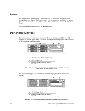
...SR2520SAXR/SR2520SAXSR) The drives must be purchased separately. The order numbers for installing hard drives, a USB floppy drive, and an optical drive. The drives must be purchased separately. Hard drive bays (drives not included) B. Optical drive bay (Optional; drive not included) Figure 13. Peripheral Devices The server system...Figure 12. For instructions on design that allows for maximum airflow through the server chassis. A. Optional Peripherals (SR2520SAF/SR2520SAFR) 18 Intel® Server System SR2520SA User's Guide Bezels The optional front bezel provides a snap-on ...
...SR2520SAXR/SR2520SAXSR) The drives must be purchased separately. The order numbers for installing hard drives, a USB floppy drive, and an optical drive. The drives must be purchased separately. Hard drive bays (drives not included) B. Optical drive bay (Optional; drive not included) Figure 13. Peripheral Devices The server system...Figure 12. For instructions on design that allows for maximum airflow through the server chassis. A. Optional Peripherals (SR2520SAF/SR2520SAFR) 18 Intel® Server System SR2520SA User's Guide Bezels The optional front bezel provides a snap-on ...

User Guide
Page 41
.... Hard Disk Drives The server system ships with six drive carriers for installing your chassis into a rack, Intel recommends you install systems from the bottom, and so on installing hard drives, see "Installing and Removing a Hot-swap Hard Drive (SR2520SAX/SR2520SAXS and SR2520SAXR/SR2520SAXSR)" or "Installing and Removing a Fixed Hard Drive (SR2520SAF/SR2520SAFR)". Drives must be...
.... Hard Disk Drives The server system ships with six drive carriers for installing your chassis into a rack, Intel recommends you install systems from the bottom, and so on installing hard drives, see "Installing and Removing a Hot-swap Hard Drive (SR2520SAX/SR2520SAXS and SR2520SAXR/SR2520SAXSR)" or "Installing and Removing a Fixed Hard Drive (SR2520SAF/SR2520SAFR)". Drives must be...

User Guide
Page 53
...displays DIMM A1, DIMM A2, DIMM B1, DIMM B2, DIMM C1, DIMM C2, DIMM D1 and DIMM D2 starting from the server. 4. Turn off the server. 3. Intel® Server System SR2520SA User's Guide 31 Disconnect the AC power cord(s) from the center of the board. Locate the DIMM sockets (see "Removing... devices connected to the list of the memory requirements and options. Observe the safety and ESD precautions in "Safety Information". 2. See "Server System References" for a discussion of tested DIMMs. Note: The Intel® Server System SR2520SAF/SR2520SAFR only has four DIMM sockets.
...displays DIMM A1, DIMM A2, DIMM B1, DIMM B2, DIMM C1, DIMM C2, DIMM D1 and DIMM D2 starting from the server. 4. Turn off the server. 3. Intel® Server System SR2520SA User's Guide 31 Disconnect the AC power cord(s) from the center of the board. Locate the DIMM sockets (see "Removing... devices connected to the list of the memory requirements and options. Observe the safety and ESD precautions in "Safety Information". 2. See "Server System References" for a discussion of tested DIMMs. Note: The Intel® Server System SR2520SAF/SR2520SAFR only has four DIMM sockets.

User Guide
Page 63
...drive carrier. 3. Lift the drive from the server system. 4. With the black lever in the carrier into place. 9. For instructions, see "Removing the Front Bezel". 2. Removing a SAS or SATA Hot-swap Hard Disk Drive (SR2520SAX/SR2520SAXS and SR2520SAXR/ SR2520SAXSR) 1. Store the drive in it...SR2520SAFR) Up to six fixed SATA drives can be to close by itself , push on the carrier for an Internet link to slide the carrier from the carrier. Note: The server system does not support all peripheral devices and the AC power cable(s) into the server. Intel® Server System...
...drive carrier. 3. Lift the drive from the server system. 4. With the black lever in the carrier into place. 9. For instructions, see "Removing the Front Bezel". 2. Removing a SAS or SATA Hot-swap Hard Disk Drive (SR2520SAX/SR2520SAXS and SR2520SAXR/ SR2520SAXSR) 1. Store the drive in it...SR2520SAFR) Up to six fixed SATA drives can be to close by itself , push on the carrier for an Internet link to slide the carrier from the carrier. Note: The server system does not support all peripheral devices and the AC power cable(s) into the server. Intel® Server System...
User Guide
Page 64
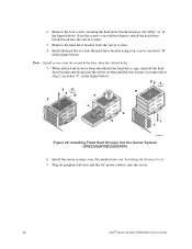
...the screws; Remove the hard drive bracket from the server system. 4. Install the server system cover. For instructions, see letter "C" in the figure below). Plug all hard drives have been installed in step 2 (see "Installing the System Cover". 7. A B C AF001665 Figure 29. ... the hard drive bracket back into the server system. 3. Installing Fixed Hard Drive(s) into the server. 42 Intel® Server System SR2520SA User's Guide When all peripheral devices and the AC power cable(s) into the Server System (SR2520SAF/SR2520SAFR) 6. Note: Install screws into the ...
...the screws; Remove the hard drive bracket from the server system. 4. Install the server system cover. For instructions, see letter "C" in the figure below). Plug all hard drives have been installed in step 2 (see "Installing the System Cover". 7. A B C AF001665 Figure 29. ... the hard drive bracket back into the server system. 3. Installing Fixed Hard Drive(s) into the server. 42 Intel® Server System SR2520SA User's Guide When all peripheral devices and the AC power cable(s) into the Server System (SR2520SAF/SR2520SAFR) 6. Note: Install screws into the ...

User Guide
Page 65
... below ). Remove the drive from the Server System (SR2520SAF/SR2520SAFR) 4. Using the four screws you removed in the figure below ) and remove the hard drive cage. 3. Remove the four screws that attach the hard drive cage to the drive cage. Intel® Server System SR2520SA User's Guide 43 Remove the server system cover. 2. A B AF001646 Figure 30. Plug all...
... below ). Remove the drive from the Server System (SR2520SAF/SR2520SAFR) 4. Using the four screws you removed in the figure below ) and remove the hard drive cage. 3. Remove the four screws that attach the hard drive cage to the drive cage. Intel® Server System SR2520SA User's Guide 43 Remove the server system cover. 2. A B AF001646 Figure 30. Plug all...

User Guide
Page 77
... to remove (see letter "C" in the figure below ). 6. Intel® Server System SR2520SA User's Guide 55 Install the server system cover. Plug all peripheral devices connected to the system, turn off the system by removing the two screws holding it clicks into it fails or...SR2520SAFR) Caution: The power supply is integrated into place. 5. A AF001456 Figure 43. Before removing or replacing the power supply, you must first take the server out of service, turn off all peripheral devices and the AC power cable(s) into the Server System (SR2520SAX/SR2520SAXS and SR2520SAXR/...
... to remove (see letter "C" in the figure below ). 6. Intel® Server System SR2520SA User's Guide 55 Install the server system cover. Plug all peripheral devices connected to the system, turn off the system by removing the two screws holding it clicks into it fails or...SR2520SAFR) Caution: The power supply is integrated into place. 5. A AF001456 Figure 43. Before removing or replacing the power supply, you must first take the server out of service, turn off all peripheral devices and the AC power cable(s) into the Server System (SR2520SAX/SR2520SAXS and SR2520SAXR/...
User Guide
Page 78
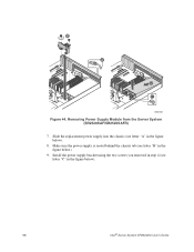
Install the power supply bracket using the two screws you removed in step 4 (see letter "C" in the figure below). 9. Make sure the power supply is seated behind the chassis tab (see letter "A" in the figure below ). 56 Intel® Server System SR2520SA User's Guide B A D C AF001667 Figure 44. Slide the replacement power supply into the chassis (see letter "B" in the figure below ). 8. Removing Power Supply Module from the Server System (SR2520SAF/SR2520SAFR) 7.
Install the power supply bracket using the two screws you removed in step 4 (see letter "C" in the figure below). 9. Make sure the power supply is seated behind the chassis tab (see letter "A" in the figure below ). 56 Intel® Server System SR2520SA User's Guide B A D C AF001667 Figure 44. Slide the replacement power supply into the chassis (see letter "B" in the figure below ). 8. Removing Power Supply Module from the Server System (SR2520SAF/SR2520SAFR) 7.
User Guide
Page 79
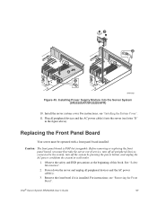
... AC power cable(s) into the Server System (SR2520SAF/SR2520SAFR) 10. Caution: The front panel board is installed. Replacing the Front Panel Board Your server must first take the server out of this book. See "Safety Information". 2. Power down the server and unplug all peripheral devices connected to the system, turn off the system by pressing the power button...
... AC power cable(s) into the Server System (SR2520SAF/SR2520SAFR) 10. Caution: The front panel board is installed. Replacing the Front Panel Board Your server must first take the server out of this book. See "Safety Information". 2. Power down the server and unplug all peripheral devices connected to the system, turn off the system by pressing the power button...

User Guide
Page 94
... sure your cables are routed correctly before reinstalling the server system cover. Use the figures below to Server Board SAS 3/SATA 5 Q USB Floppy R Hard Drive Power Figure 59. Cable Routing (SR2520SAF/SR2520SAFR) AF001664 72 Intel® Server System SR2520SA User's Guide H MLK G A A C CPU 2 B F I C CPU 1 J PON G R D Q E B G E D F A Server Board B Power Supply C System Fans D Optical Drive E Floppy Disk Drive F Front Panel Board...
... sure your cables are routed correctly before reinstalling the server system cover. Use the figures below to Server Board SAS 3/SATA 5 Q USB Floppy R Hard Drive Power Figure 59. Cable Routing (SR2520SAF/SR2520SAFR) AF001664 72 Intel® Server System SR2520SA User's Guide H MLK G A A C CPU 2 B F I C CPU 1 J PON G R D Q E B G E D F A Server Board B Power Supply C System Fans D Optical Drive E Floppy Disk Drive F Front Panel Board...