
User Guide
Page 5
... BIOS settings and screens is written for system technicians who are responsible for troubleshooting, upgrading, and repairing this Manual Thank you will find a list of this manual, see the Intel® Server Board S5000VSA User's Guide. Use this chapter you for installing or replacing components such as the fans, power supply, drives, and other components.
... BIOS settings and screens is written for system technicians who are responsible for troubleshooting, upgrading, and repairing this Manual Thank you will find a list of this manual, see the Intel® Server Board S5000VSA User's Guide. Use this chapter you for installing or replacing components such as the fans, power supply, drives, and other components.

User Guide
Page 6
Intel® Server System SR2520SAX/SR2520SAXR Contents Your Intel® Server System SR2520SAX/SR2520SAXR ships with the following items: • Intel® Server Board S5000VSA (SATA SKU), installed in the server system • One 600 W hot-swap power supply module, installed in the server system • Hot-swap power cage, installed in the server system • Two 80mm system fans, installed in the server system • One 60mm system fan, installed in the server system •...
Intel® Server System SR2520SAX/SR2520SAXR Contents Your Intel® Server System SR2520SAX/SR2520SAXR ships with the following items: • Intel® Server Board S5000VSA (SATA SKU), installed in the server system • One 600 W hot-swap power supply module, installed in the server system • Hot-swap power cage, installed in the server system • Two 80mm system fans, installed in the server system • One 60mm system fan, installed in the server system •...

User Guide
Page 7
Intel® Server System SR2520SAXS/SR2520SAXSR Contents Your Intel® Server System SR2520SAXS/SR2520SAXSR ships with the following items: • Intel® Server Board S5000VSA (SAS SKU), installed in the server system • One 600 W hot-swap power supply module, installed in the server system • Hot-swap power cage, installed in the server system • Two 80mm system fans, installed in the server system • One 60mm system fan, installed in...
Intel® Server System SR2520SAXS/SR2520SAXSR Contents Your Intel® Server System SR2520SAXS/SR2520SAXSR ships with the following items: • Intel® Server Board S5000VSA (SAS SKU), installed in the server system • One 600 W hot-swap power supply module, installed in the server system • Hot-swap power cage, installed in the server system • Two 80mm system fans, installed in the server system • One 60mm system fan, installed in...

User Guide
Page 8
...; Server System SR2520SAF/SR2520SAFR Contents Your Intel® Server System SR2520SAF/SR2520SAFR ships with the following items: • Intel® Server Board S5000VSA (4 DIMM SKU), installed in the server system • One 600 W fixed power supply module, installed in the server system • Two 80mm system fans, installed in the server system • One 60mm system fan, installed in the server system • CPU air duct, installed in the server system...
...; Server System SR2520SAF/SR2520SAFR Contents Your Intel® Server System SR2520SAF/SR2520SAFR ships with the following items: • Intel® Server Board S5000VSA (4 DIMM SKU), installed in the server system • One 600 W fixed power supply module, installed in the server system • Two 80mm system fans, installed in the server system • One 60mm system fan, installed in the server system • CPU air duct, installed in the server system...

User Guide
Page 14
...-in Card 49 Installing and Removing the Server Board 50 Installing the Server Board 50 Removing the Server Board 51 Replacing the Backup Battery 52 Replacing the Redundant Power Supply (SR2520SAX/SR2520SAXS and SR2520SAXR/ SR2520SAXSR) ...54 Replacing the Fixed Power Supply (SR2520SAF/SR2520SAFR 55 Replacing the Front Panel Board 57 Replacing a System Fan ...60 Installing and Removing the Rack...
...-in Card 49 Installing and Removing the Server Board 50 Installing the Server Board 50 Removing the Server Board 51 Replacing the Backup Battery 52 Replacing the Redundant Power Supply (SR2520SAX/SR2520SAXS and SR2520SAXR/ SR2520SAXSR) ...54 Replacing the Fixed Power Supply (SR2520SAF/SR2520SAFR 55 Replacing the Front Panel Board 57 Replacing a System Fan ...60 Installing and Removing the Rack...

User Guide
Page 15
... Single Power Supply Input Voltages 73 600W Single Power Supply Output Voltages 73 System Environmental Specifications 74 Appendix B: LED Decoder (SR2520SAX /SR2520SAXS and SR2520SAXR/ SR2520SAXSR Only 75 Appendix C: Getting Help 81 World Wide Web ...81 Telephone ...81 Appendix D: Regulatory and Compliance Information 85 Product Regulatory Compliance 85 Product Safety Compliance 85 Product EMC Compliance - Preparing for Intel...
... Single Power Supply Input Voltages 73 600W Single Power Supply Output Voltages 73 System Environmental Specifications 74 Appendix B: LED Decoder (SR2520SAX /SR2520SAXS and SR2520SAXR/ SR2520SAXSR Only 75 Appendix C: Getting Help 81 World Wide Web ...81 Telephone ...81 Appendix D: Regulatory and Compliance Information 85 Product Regulatory Compliance 85 Product Safety Compliance 85 Product EMC Compliance - Preparing for Intel...

User Guide
Page 20
... Figure 58. Cable Routing (SR2520SAX/SR2520SAXS and SR2520SAXR/SR2520SAXSR) 71 Figure 59. Removing the Front Panel Board 58 Figure 47. Cable Routing (SR2520SAF/SR2520SAFR 72 xx Intel® Server System SR2520SA User's Guide Installing Optical Drive and Drive...Installing Power Supply Module into the Server System (SR2520SAX/SR2520SAXS and SR2520SAXR/SR2520SAXSR 55 Figure 44. Figure 34. Removing a Fan from the Server System 47 Figure 36. Installing the Server Board 50 Figure 40. Removing Optical Drive from the Server System (SR2520SAX/ SR2520SAXS and SR2520SAXR/SR2520SAXSR...
... Figure 58. Cable Routing (SR2520SAX/SR2520SAXS and SR2520SAXR/SR2520SAXSR) 71 Figure 59. Removing the Front Panel Board 58 Figure 47. Cable Routing (SR2520SAF/SR2520SAFR 72 xx Intel® Server System SR2520SA User's Guide Installing Optical Drive and Drive...Installing Power Supply Module into the Server System (SR2520SAX/SR2520SAXS and SR2520SAXR/SR2520SAXSR 55 Figure 44. Figure 34. Removing a Fan from the Server System 47 Figure 36. Installing the Server Board 50 Figure 40. Removing Optical Drive from the Server System (SR2520SAX/ SR2520SAXS and SR2520SAXR/SR2520SAXSR...

User Guide
Page 21
Setup Menu Key Use 66 Table 5. POST Progress Code LED Example 75 Table 8. Resetting the System 97 Table 11. List of Tables Table 1. Diagnostic LED POST Code Decoder 76 Table 9. NIC LED Descriptions 14 Table 4. Power Supply Output Capability 73 Table 6. Product Regulatory Compliance Markings 87 Table 10. POST Error Beep Codes 106 Intel® Server System SR2520SA User's Guide xxi LED Information ...106 Table 12. Server System References 1 Table 2. System Environmental Specifications 74 Table 7. Intel® Server System SR2520SA Feature Summary 4 Table 3.
Setup Menu Key Use 66 Table 5. POST Progress Code LED Example 75 Table 8. Resetting the System 97 Table 11. List of Tables Table 1. Diagnostic LED POST Code Decoder 76 Table 9. NIC LED Descriptions 14 Table 4. Power Supply Output Capability 73 Table 6. Product Regulatory Compliance Markings 87 Table 10. POST Error Beep Codes 106 Intel® Server System SR2520SA User's Guide xxi LED Information ...106 Table 12. Server System References 1 Table 2. System Environmental Specifications 74 Table 7. Intel® Server System SR2520SA Feature Summary 4 Table 3.
User Guide
Page 28
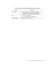
Intel® Server System SR2520SA Feature Summary Feature Power Supply Fans System Management Description • Single 600 W power supply module (SR2520SAF) • Redundant 600 W power supply modules (SR2520SAX/ SR2520SAXS and SR2520SAXR/SR2520SAXSR) • Three system cooling fans • Two non-redundant fans in power supply Intel® System Management Software 6 Intel® Server System SR2520SA User's Guide Table 2.
Intel® Server System SR2520SA Feature Summary Feature Power Supply Fans System Management Description • Single 600 W power supply module (SR2520SAF) • Redundant 600 W power supply modules (SR2520SAX/ SR2520SAXS and SR2520SAXR/SR2520SAXSR) • Three system cooling fans • Two non-redundant fans in power supply Intel® System Management Software 6 Intel® Server System SR2520SA User's Guide Table 2.
User Guide
Page 29
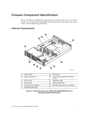
Front Panel H. Hard Drive Bays (drives not included) Figure 2. Optical Drive Bay J. System Cooling Fans C. Hot-Swap Power Cage G. Control Panel (standard control panel shown) I H F G A AF001442 A. CPU Air Duct D. Server Board E. Hot-Swap Power Supplies F. Internal Components D C B E A K J I . Rack Handles B. ChassisComponents (SR2520SAX/SR2520SAXS and SR2520SAXR/SR2520SAXSR) Intel® Server System SR2520SA User's Guide 7 Slimline Floppy Drive K. If you are near the...
Front Panel H. Hard Drive Bays (drives not included) Figure 2. Optical Drive Bay J. System Cooling Fans C. Hot-Swap Power Cage G. Control Panel (standard control panel shown) I H F G A AF001442 A. CPU Air Duct D. Server Board E. Hot-Swap Power Supplies F. Internal Components D C B E A K J I . Rack Handles B. ChassisComponents (SR2520SAX/SR2520SAXS and SR2520SAXR/SR2520SAXSR) Intel® Server System SR2520SA User's Guide 7 Slimline Floppy Drive K. If you are near the...

User Guide
Page 30
CPU Air Duct D. Hard Drive Bays (drives not included) Figure 3. Fixed Power Supply F. Control Panel (standard control panel shown) I H G A F AF001663 A. Server Board E. Front Panel H. Power Distribution Board G. Slimline Floppy Drive K. ChassisComponents (SR2520SAF/SR2520SAFR) 8 Intel® Server System SR2520SA User's Guide D C B A E K J I . Optical Drive Bay J. Rack Handles B. System Cooling Fans C.
CPU Air Duct D. Hard Drive Bays (drives not included) Figure 3. Fixed Power Supply F. Control Panel (standard control panel shown) I H G A F AF001663 A. Server Board E. Front Panel H. Power Distribution Board G. Slimline Floppy Drive K. ChassisComponents (SR2520SAF/SR2520SAFR) 8 Intel® Server System SR2520SA User's Guide D C B A E K J I . Optical Drive Bay J. Rack Handles B. System Cooling Fans C.
User Guide
Page 35
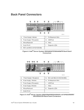
.../1000 Mb) H. Intel® Server System SR2520SAX/SR2520SAXS and SR2520SAXR/ SR2520SAXSR Back Panel Connectors Intel® Server System SR2520SA User's Guide 13 Serial Port A E. Intel® Server System SR2520SAF/SR2520SAFR Back Panel Connectors AB CD E F G H K J I . Power Supply 1 Module C. Mouse/Keyboard F. USB Ports J. Serial Port A G. Video I AF001441 A. Back Panel Connectors A BC D E F I . NIC1 and NIC2 (10/100/1000 Mb) F. PCI Expansion Slots I H G AF001475 A. Video K. Power Supply 1 Receptacle C. Power Supply 1 Receptacle B. Power Supply...
.../1000 Mb) H. Intel® Server System SR2520SAX/SR2520SAXS and SR2520SAXR/ SR2520SAXSR Back Panel Connectors Intel® Server System SR2520SA User's Guide 13 Serial Port A E. Intel® Server System SR2520SAF/SR2520SAFR Back Panel Connectors AB CD E F G H K J I . Power Supply 1 Module C. Mouse/Keyboard F. USB Ports J. Serial Port A G. Video I AF001441 A. Back Panel Connectors A BC D E F I . NIC1 and NIC2 (10/100/1000 Mb) F. PCI Expansion Slots I H G AF001475 A. Video K. Power Supply 1 Receptacle C. Power Supply 1 Receptacle B. Power Supply...
User Guide
Page 76
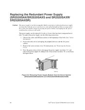
... power supply, you must first take the server out of the system (see "Removing the System Cover". 4. Power down the server and unplug all peripheral devices connected to disengage the power supply (see letter "A") and remove the power supply by pressing the power button, and unplug the AC power cord from the Server System (SR2520SAX/SR2520SAXS and SR2520SAXR/SR2520SAXSR) 54 Intel® Server System SR2520SA User's Guide Remove the server system...
... power supply, you must first take the server out of the system (see "Removing the System Cover". 4. Power down the server and unplug all peripheral devices connected to disengage the power supply (see letter "A") and remove the power supply by pressing the power button, and unplug the AC power cord from the Server System (SR2520SAX/SR2520SAXS and SR2520SAXR/SR2520SAXSR) 54 Intel® Server System SR2520SA User's Guide Remove the server system...

User Guide
Page 77
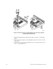
... ). 3. Intel® Server System SR2520SA User's Guide 55 A AF001456 Figure 43. Plug all peripheral devices and the AC power cable (see letter "D" in the figure below ). 5. Power down the server and unplug all peripheral devices and the AC power cable(s) into the Server System (SR2520SAX/SR2520SAXS and SR2520SAXR/SR2520SAXSR) 6. Installing Power Supply Module into the server. Replacing the Fixed Power Supply (SR2520SAF/ SR2520SAFR) Caution: The power supply...
... ). 3. Intel® Server System SR2520SA User's Guide 55 A AF001456 Figure 43. Plug all peripheral devices and the AC power cable (see letter "D" in the figure below ). 5. Power down the server and unplug all peripheral devices and the AC power cable(s) into the Server System (SR2520SAX/SR2520SAXS and SR2520SAXR/SR2520SAXSR) 6. Installing Power Supply Module into the server. Replacing the Fixed Power Supply (SR2520SAF/ SR2520SAFR) Caution: The power supply...
User Guide
Page 78
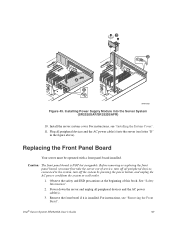
Make sure the power supply is seated behind the chassis tab (see letter "A" in the figure below). 8. Slide the replacement power supply into the chassis (see letter "B" in the figure below ). 9. Install the power supply bracket using the two screws you removed in step 4 (see letter "C" in the figure below ). 56 Intel® Server System SR2520SA User's Guide B A D C AF001667 Figure 44. Removing Power Supply Module from the Server System (SR2520SAF/SR2520SAFR) 7.
Make sure the power supply is seated behind the chassis tab (see letter "A" in the figure below). 8. Slide the replacement power supply into the chassis (see letter "B" in the figure below ). 9. Install the power supply bracket using the two screws you removed in step 4 (see letter "C" in the figure below ). 56 Intel® Server System SR2520SA User's Guide B A D C AF001667 Figure 44. Removing Power Supply Module from the Server System (SR2520SAF/SR2520SAFR) 7.
User Guide
Page 79
... off the system by pressing the power button, and unplug the AC power cord from the system or wall outlet. 1. Plug all peripheral devices and the AC power cable(s). 3. For instructions, see letter "D" in the figure above). Installing Power Supply Module into the server (see "Installing the System Cover". 11. Intel® Server System SR2520SA User's Guide 57 Install the server system cover. See...
... off the system by pressing the power button, and unplug the AC power cord from the system or wall outlet. 1. Plug all peripheral devices and the AC power cable(s). 3. For instructions, see letter "D" in the figure above). Installing Power Supply Module into the server (see "Installing the System Cover". 11. Intel® Server System SR2520SA User's Guide 57 Install the server system cover. See...
User Guide
Page 82
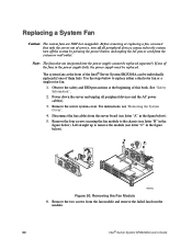
... fan cables from the module. 60 Intel® Server System SR2520SA User's Guide Removing the Fan Module 6. The system fans at the beginning of them fails. Power down the server and unplug all peripheral devices connected to the chassis (see "Removing the System Cover". 4. For instructions, see letter... Remove the server system cover. Note: The fans that are NOT hot swappable. Remove the two screws from the fan module and remove the failed fan from the server board (see letter "C" in the power supply fails, the power supply must first take the server out of ...
... fan cables from the module. 60 Intel® Server System SR2520SA User's Guide Removing the Fan Module 6. The system fans at the beginning of them fails. Power down the server and unplug all peripheral devices connected to the chassis (see "Removing the System Cover". 4. For instructions, see letter... Remove the server system cover. Note: The fans that are NOT hot swappable. Remove the two screws from the fan module and remove the failed fan from the server board (see letter "C" in the power supply fails, the power supply must first take the server out of ...
User Guide
Page 93
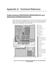
... SR2520SAXR/SR2520SAXSR) When you add or remove components from your server system, make sure no cables or wires are routed correctly before reinstalling the server system cover. C B A A C CPU 2 B CPU 1 F H I J E D G J Q MLK N I PG H O G E D F A Server Board B Power Supply #1 C Power Supply #2 D Power Distribution Module E System Fans F Front Panel Board G Floppy Disk Drive H Optical Drive I Hard Disk Drive Bays J Backplane A Power to Server Board (Main) B Power to Server Board (CPU) C Power to Server...
... SR2520SAXR/SR2520SAXSR) When you add or remove components from your server system, make sure no cables or wires are routed correctly before reinstalling the server system cover. C B A A C CPU 2 B CPU 1 F H I J E D G J Q MLK N I PG H O G E D F A Server Board B Power Supply #1 C Power Supply #2 D Power Distribution Module E System Fans F Front Panel Board G Floppy Disk Drive H Optical Drive I Hard Disk Drive Bays J Backplane A Power to Server Board (Main) B Power to Server Board (CPU) C Power to Server...

User Guide
Page 94
... Server Board B Power Supply C System Fans D Optical Drive E Floppy Disk Drive F Front Panel Board G Hard Disk Drive Bays A Power to Server Board (Main) B Power to Server Board (CPU) C Power to Server Board (Auxiliary) D Front Panel USB E Front Panel F Optical Device Data Cable G Optical Device Power H Fan #1 Power I Fan #2 Power J Fan #3 Power K HDD 0 to Server Board SATA 0 L HDD 1 to Server Board...the figures below to Server Board SAS 3/SATA 5 Q USB Floppy R Hard Drive Power Figure 59. Cable Routing (SR2520SAF/SR2520SAFR) AF001664 72 Intel® Server System SR2520SA User's Guide ...
... Server Board B Power Supply C System Fans D Optical Drive E Floppy Disk Drive F Front Panel Board G Hard Disk Drive Bays A Power to Server Board (Main) B Power to Server Board (CPU) C Power to Server Board (Auxiliary) D Front Panel USB E Front Panel F Optical Device Data Cable G Optical Device Power H Fan #1 Power I Fan #2 Power J Fan #3 Power K HDD 0 to Server Board SATA 0 L HDD 1 to Server Board...the figures below to Server Board SAS 3/SATA 5 Q USB Floppy R Hard Drive Power Figure 59. Cable Routing (SR2520SAF/SR2520SAFR) AF001664 72 Intel® Server System SR2520SA User's Guide ...
User Guide
Page 95
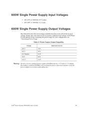
... will overload the power subsystem and may cause the power supplies to overheat and malfunction. For information about calculating the power usage for your loads do not exceed the combined total wattage of 90 Watts for each voltage. Intel® Server System SR2520SA User's Guide 73 Table 5. Ensure that your configuration, see "Calculating Power Usage." Power Supply Output Capability Voltage...
... will overload the power subsystem and may cause the power supplies to overheat and malfunction. For information about calculating the power usage for your loads do not exceed the combined total wattage of 90 Watts for each voltage. Intel® Server System SR2520SA User's Guide 73 Table 5. Ensure that your configuration, see "Calculating Power Usage." Power Supply Output Capability Voltage...
