User Guide
Page 15
... Figure 40. Rear Panel Components 5 Figure 4. Applying Label to Chassis 149 Figure 29. Re-installing Drive Carrier into Storage System 14 Figure 11. Securing New Power Supply Cage to Hard Disk 13 Figure 9. Re-installing Drive Carriers 157 Figure 37. RAID 1 - Removing...Old Power Supply 148 Figure 26. Removing Drive Carriers 152 Figure 32. RAID 0 - Rear View of RAID 1 and RAID 0 172 Intel® Entry Storage System SS4000-E User Guide xv RAID 5 - Combination of SATA Hard Disk 12 Figure 7. Rear View of Figures Figure 1. Installing Hard Disk into...
... Figure 40. Rear Panel Components 5 Figure 4. Applying Label to Chassis 149 Figure 29. Re-installing Drive Carrier into Storage System 14 Figure 11. Securing New Power Supply Cage to Hard Disk 13 Figure 9. Re-installing Drive Carriers 157 Figure 37. RAID 1 - Removing...Old Power Supply 148 Figure 26. Removing Drive Carriers 152 Figure 32. RAID 0 - Rear View of RAID 1 and RAID 0 172 Intel® Entry Storage System SS4000-E User Guide xv RAID 5 - Combination of SATA Hard Disk 12 Figure 7. Rear View of Figures Figure 1. Installing Hard Disk into...

User Guide
Page 18
... that you can start with one fails, you can set up to the system. 2 Intel® Entry Storage System SS4000-E User Guide If your needs grow. See the Tested Hardware and Operating Systems List at http:// support.intel.com/support/motherboards/server/ss4000-e/ for each of them. • Security: Only authorized users can access the shared folders on multiple platforms: Whether...
... that you can start with one fails, you can set up to the system. 2 Intel® Entry Storage System SS4000-E User Guide If your needs grow. See the Tested Hardware and Operating Systems List at http:// support.intel.com/support/motherboards/server/ss4000-e/ for each of them. • Security: Only authorized users can access the shared folders on multiple platforms: Whether...
User Guide
Page 22
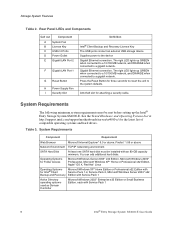
See the Tested Hardware and Operating Systems List at http://support.intel.com/support/motherboards/server/ss4000-e/ for three seconds to revert the unit to a gigabit network. SATA Hard Disk At least one SATA hard disk must be installed with Service Pack 1 6 Intel® Entry Storage System SS4000-E User Guide System Requirements Component Requirement Web Browser Microsoft Internet Explorer* 6.0 or above...
See the Tested Hardware and Operating Systems List at http://support.intel.com/support/motherboards/server/ss4000-e/ for three seconds to revert the unit to a gigabit network. SATA Hard Disk At least one SATA hard disk must be installed with Service Pack 1 6 Intel® Entry Storage System SS4000-E User Guide System Requirements Component Requirement Web Browser Microsoft Internet Explorer* 6.0 or above...

User Guide
Page 43
.... For more information, see "Changing the System Settings" on page 66. 3. These are casesensitive. Once you log in, you can view or change both the administrator user name and password at any of the storage system settings. Getting Started Logging in to the ...Manager To ensure your connection to the Manager: 1. Click Log In. To log in to the storage system is secure, the HTTPS protocol is storage. Intel® Entry Storage System SS4000-E User Guide 27
.... For more information, see "Changing the System Settings" on page 66. 3. These are casesensitive. Once you log in, you can view or change both the administrator user name and password at any of the storage system settings. Getting Started Logging in to the ...Manager To ensure your connection to the Manager: 1. Click Log In. To log in to the storage system is secure, the HTTPS protocol is storage. Intel® Entry Storage System SS4000-E User Guide 27

User Guide
Page 48
...default, the Intel® Entry Storage System SS4000-E includes a user named guest that guest is authorized to access it. Linux users and Mac users who can add only Linux/other Mac users. In the navigation bar, click Users. If your network provides flexibility and security, enabling you ... you to add other Mac user can represent multiple users, the number of guest. The Users & Computers page displays. 32 Intel® Entry Storage System SS4000-E User Guide Microsoft Windows* and Mac OS X* users can use Active Directory authentication mode instead. Since all user data and ...
...default, the Intel® Entry Storage System SS4000-E includes a user named guest that guest is authorized to access it. Linux users and Mac users who can add only Linux/other Mac users. In the navigation bar, click Users. If your network provides flexibility and security, enabling you ... you to add other Mac user can represent multiple users, the number of guest. The Users & Computers page displays. 32 Intel® Entry Storage System SS4000-E User Guide Microsoft Windows* and Mac OS X* users can use Active Directory authentication mode instead. Since all user data and ...

User Guide
Page 80
...1.0 , 1.1, 1.2, or 1.3 to recover the system disk using the recovery CD, or if the system disk was not protected, re-install the operating system. In the navigation bar, click Advanced. 2. Click Upgrade. 6. For additional security, you will need to version 1.4. Upgrading to ... Back up your storage system. When the confirmation message displays, click OK. 64 Intel® Entry Storage System SS4000-E User Guide It also allows you upgrade the firmware. • Restarting the storage system when a backup is being recovered can potentially corrupt the operating system, and you must ...
...1.0 , 1.1, 1.2, or 1.3 to recover the system disk using the recovery CD, or if the system disk was not protected, re-install the operating system. In the navigation bar, click Advanced. 2. Click Upgrade. 6. For additional security, you will need to version 1.4. Upgrading to ... Back up your storage system. When the confirmation message displays, click OK. 64 Intel® Entry Storage System SS4000-E User Guide It also allows you upgrade the firmware. • Restarting the storage system when a backup is being recovered can potentially corrupt the operating system, and you must ...

User Guide
Page 88
...space is available), but you cannot reduce it is allocated for additional security, you must click Refresh to update the hot-plug indicator. However, for shared folders at any time. Expanding the Shared Storage The disk space on the Home page shows how much disk space ...by backups, and how much is divided into two portions. The Storage Status view on your computer disks. The Shared Folders page displays: 72 Intel® Entry Storage System SS4000-E User Guide Note: Whenever you add or remove a disk from the storage system, you plan to protect have been backed up to expand. ...
...space is available), but you cannot reduce it is allocated for additional security, you must click Refresh to update the hot-plug indicator. However, for shared folders at any time. Expanding the Shared Storage The disk space on the Home page shows how much disk space ...by backups, and how much is divided into two portions. The Storage Status view on your computer disks. The Shared Folders page displays: 72 Intel® Entry Storage System SS4000-E User Guide Note: Whenever you add or remove a disk from the storage system, you plan to protect have been backed up to expand. ...

User Guide
Page 107
... Software Initiator are using a firewall on the computer that you must remove the storage system from the list of backup locations and add it for the first time. Intel® Entry Storage System SS4000-E User Guide 91 If your firewall does not block incoming network communication to install... a Web browser, enter the following criteria must be met: • You must download and install the Microsoft iSCSI Initiator* 2.x. If a security warning displays, click Run. The installation wizard starts. 5. On the first page of underscores (_) in "Protecting Your Disks" on page 98....
... Software Initiator are using a firewall on the computer that you must remove the storage system from the list of backup locations and add it for the first time. Intel® Entry Storage System SS4000-E User Guide 91 If your firewall does not block incoming network communication to install... a Web browser, enter the following criteria must be met: • You must download and install the Microsoft iSCSI Initiator* 2.x. If a security warning displays, click Run. The installation wizard starts. 5. On the first page of underscores (_) in "Protecting Your Disks" on page 98....

User Guide
Page 153
... and module connectors. Caution: It is facing the front of the storage system as it would be secured by tightening the retaining screw with a screwdriver. Removing or Installing the Enclosure Cover Warning: The enclosure cover must only be done by a service personnel. Intel® Entry Storage System SS4000-E User Guide 137 Hardware Installations and Upgrades 7 Hardware Installations and...
... and module connectors. Caution: It is facing the front of the storage system as it would be secured by tightening the retaining screw with a screwdriver. Removing or Installing the Enclosure Cover Warning: The enclosure cover must only be done by a service personnel. Intel® Entry Storage System SS4000-E User Guide 137 Hardware Installations and Upgrades 7 Hardware Installations and...

User Guide
Page 155
Secure the enclosure cover to its power source. 4. Installing Enclosure Cover AF000240 3. Power up . Reconnect the storage system to the chassis with the edge at the bottom of the chassis and slide the enclosure cover downward. Intel® Entry Storage System SS4000-E User Guide 139 A B B B B K Figure 14. The System Status LED flashes green while the system is booting up the storage system by...
Secure the enclosure cover to its power source. 4. Installing Enclosure Cover AF000240 3. Power up . Reconnect the storage system to the chassis with the edge at the bottom of the chassis and slide the enclosure cover downward. Intel® Entry Storage System SS4000-E User Guide 139 A B B B B K Figure 14. The System Status LED flashes green while the system is booting up the storage system by...

User Guide
Page 163
... Chassis AF000292 7. See letter "A" in the following figure. See letter "C". See letter "A" in the power supply enclosure. Disconnecting Power Cables and Removing Power Supply Cage Intel® Entry Storage System SS4000-E User Guide 147 A A K Figure 23. Hardware Installations and Upgrades 6. Remove the three screws securing the old power supply to the chassis. See letter "B".
... Chassis AF000292 7. See letter "A" in the following figure. See letter "C". See letter "A" in the power supply enclosure. Disconnecting Power Cables and Removing Power Supply Cage Intel® Entry Storage System SS4000-E User Guide 147 A A K Figure 23. Hardware Installations and Upgrades 6. Remove the three screws securing the old power supply to the chassis. See letter "B".

User Guide
Page 164
A A A AF000302 Figure 26. A A A AF000301 Figure 25. See letter "A" in the following figure. Remove the three screws securing the power supply gasket to the new power supply with the three screws removed in the previous step. Attach the power supply gasket to the old power supply See letter "A" in the following figure. Installing Gasket on New Power Supply 148 Intel® Entry Storage System SS4000-E User Guide Removing Gasket from Old Power Supply 9. Hardware Installations and Upgrades 8.
A A A AF000302 Figure 26. A A A AF000301 Figure 25. See letter "A" in the following figure. Remove the three screws securing the power supply gasket to the new power supply with the three screws removed in the previous step. Attach the power supply gasket to the old power supply See letter "A" in the following figure. Installing Gasket on New Power Supply 148 Intel® Entry Storage System SS4000-E User Guide Removing Gasket from Old Power Supply 9. Hardware Installations and Upgrades 8.

User Guide
Page 165
Feed power supply cables through the opening in the following figure. Secure the power supply cage to Chassis AF000292 Intel® Entry Storage System SS4000-E User Guide 149 Securing New Power Supply Cage to the chassis with three screws. Hardware Installations and Upgrades 10. See letter "D". Slide the new power supply cage into the ...
Feed power supply cables through the opening in the following figure. Secure the power supply cage to Chassis AF000292 Intel® Entry Storage System SS4000-E User Guide 149 Securing New Power Supply Cage to the chassis with three screws. Hardware Installations and Upgrades 10. See letter "D". Slide the new power supply cage into the ...

User Guide
Page 166
... up . 150 Intel® Entry Storage System SS4000-E User Guide Installing Enclosure Cover AF000240 13. See letter "B". A B B B B K Figure 29. Hardware Installations and Upgrades 12. Align the guide on the front of the chassis and slide the enclosure cover downward. Reconnect the storage system to the chassis with the edge at the bottom of the unit. Secure the enclosure...
... up . 150 Intel® Entry Storage System SS4000-E User Guide Installing Enclosure Cover AF000240 13. See letter "B". A B B B B K Figure 29. Hardware Installations and Upgrades 12. Align the guide on the front of the chassis and slide the enclosure cover downward. Reconnect the storage system to the chassis with the edge at the bottom of the unit. Secure the enclosure...

User Guide
Page 169
Remove the four hex-head screws, two per side, that secure the backplane assembly to the chassis. Removing Backplane from its connector on the system board by pulling it up. See letter "A" in the following figure. See letter "C". Disconnect the backplane assembly from Chassis Intel® Entry Storage System SS4000-E User Guide 153 C A B AF000296 Figure 32. Hardware Installations and Upgrades 7. Lift the backplane assembly from the chassis. See letter "B".
Remove the four hex-head screws, two per side, that secure the backplane assembly to the chassis. Removing Backplane from its connector on the system board by pulling it up. See letter "A" in the following figure. See letter "C". Disconnect the backplane assembly from Chassis Intel® Entry Storage System SS4000-E User Guide 153 C A B AF000296 Figure 32. Hardware Installations and Upgrades 7. Lift the backplane assembly from the chassis. See letter "B".

User Guide
Page 170
Remove the old system fan from the system board. C B B A Figure 33. Remove the four screws securing the old system fan to the chassis. Removing System Fan B B K AF000297 154 Intel® Entry Storage System SS4000-E User Guide Hardware Installations and Upgrades 8. See letter "B". See letter "C". Disconnect the fan power cable from the chassis. See letter "A" in the following figure.
Remove the old system fan from the system board. C B B A Figure 33. Remove the four screws securing the old system fan to the chassis. Removing System Fan B B K AF000297 154 Intel® Entry Storage System SS4000-E User Guide Hardware Installations and Upgrades 8. See letter "B". See letter "C". Disconnect the fan power cable from the chassis. See letter "A" in the following figure.

User Guide
Page 171
Hardware Installations and Upgrades 9. Secure the new system fan to its connector on the system board. Align the holes in chassis. See letter "C". Installing New System Fan AF000298 Intel® Entry Storage System SS4000-E User Guide 155 Fan airflow exits the back of airflow. See letter "B". Route the fan cable through the opening provided in the following figure. See ...
Hardware Installations and Upgrades 9. Secure the new system fan to its connector on the system board. Align the holes in chassis. See letter "C". Installing New System Fan AF000298 Intel® Entry Storage System SS4000-E User Guide 155 Fan airflow exits the back of airflow. See letter "B". Route the fan cable through the opening provided in the following figure. See ...

User Guide
Page 172
Re-installing Backplane Assembly 156 Intel® Entry Storage System SS4000-E User Guide Ensure the backplane assembly fully connects to the chassis with four screws, two per side. See letter "C". See letter "B". Slide the backplane assembly into the guides on the system board. Secure the backplane assembly to its connector on each side of the chassis See letter "A" in the following figure. A C B AF000299 Figure 35. Hardware Installations and Upgrades 10.
Re-installing Backplane Assembly 156 Intel® Entry Storage System SS4000-E User Guide Ensure the backplane assembly fully connects to the chassis with four screws, two per side. See letter "C". See letter "B". Slide the backplane assembly into the guides on the system board. Secure the backplane assembly to its connector on each side of the chassis See letter "A" in the following figure. A C B AF000299 Figure 35. Hardware Installations and Upgrades 10.

User Guide
Page 174
... with the edge at the bottom of the unit. Hardware Installations and Upgrades 12. See letter "B". Power up . 158 Intel® Entry Storage System SS4000-E User Guide See letter "A" in the following figure. A B B B B K Figure 37. Secure the enclosure cover to its power source. 14. Align the guide on the front of the chassis and slide the...
... with the edge at the bottom of the unit. Hardware Installations and Upgrades 12. See letter "B". Power up . 158 Intel® Entry Storage System SS4000-E User Guide See letter "A" in the following figure. A B B B B K Figure 37. Secure the enclosure cover to its power source. 14. Align the guide on the front of the chassis and slide the...