
User Guide
Page 2
... published operating or non-operating limits. Intel, Intel Pentium, and Intel Xeon are not designed, intended or authorized for use Intel developed server building blocks to consult vendor datasheets and operating parameters to sale and/or use of the Intel product could create a situation where personal injury or death may occur. All Rights Reserved ii Intel® Entry Storage System SS4200-E User Guide Intel products...
... published operating or non-operating limits. Intel, Intel Pentium, and Intel Xeon are not designed, intended or authorized for use Intel developed server building blocks to consult vendor datasheets and operating parameters to sale and/or use of the Intel product could create a situation where personal injury or death may occur. All Rights Reserved ii Intel® Entry Storage System SS4200-E User Guide Intel products...

User Guide
Page 4
...storage server, place the board component side up on the board. System power on/off: The power button DOES NOT turn off the storage system and disconnect the power cord, telecommunications systems... their edges. Operating it . To remove power from storage system, you open ...storage system when handling parts. Installing or removing jumpers: A jumper is sold. Do not touch the connector contacts. Safety Information Warnings These warnings and cautions apply whenever you perform all procedures in this document only at an ESD workstation. iv Intel® Entry Storage System SS4200...
...storage server, place the board component side up on the board. System power on/off: The power button DOES NOT turn off the storage system and disconnect the power cord, telecommunications systems... their edges. Operating it . To remove power from storage system, you open ...storage system when handling parts. Installing or removing jumpers: A jumper is sold. Do not touch the connector contacts. Safety Information Warnings These warnings and cautions apply whenever you perform all procedures in this document only at an ESD workstation. iv Intel® Entry Storage System SS4200...

User Guide
Page 6
... this product and need to install it Intel® Entry Storage System SS4200-E Technical Product Specification http://support.intel.com/support/motherboards/server/ss4200-e/ Intel® Entry Storage System SS4200-E Quick Start User's Guide in the product box Accessories or other Intel Spares and Configuration Guide server products Hardware (peripherals, hard disk drives) and operating systems that have been validated by Intel for this Web page, type the...
... this product and need to install it Intel® Entry Storage System SS4200-E Technical Product Specification http://support.intel.com/support/motherboards/server/ss4200-e/ Intel® Entry Storage System SS4200-E Quick Start User's Guide in the product box Accessories or other Intel Spares and Configuration Guide server products Hardware (peripherals, hard disk drives) and operating systems that have been validated by Intel for this Web page, type the...
User Guide
Page 7
...About this Manual ...v Product Contents, Order Options, and Accessories v Additional Information and Software v Storage System Features 1 Enclosure Core Product ...1 Chassis ...3 System Board Subsystem ...3 System Board I/O Panel ...4 System Board Layout ...5 Front Panel ...6 Rear Panel ...6 Power Supply ...7 Power Supply Output Loom ... Server 10 Planning and Configuring Your Installation 10 Power Cord Connection ...10 Grounding Checks ...10 Operation ...11 Before You Begin ...11 Power On ...11 Starting the Drives ...11 Disk Drive Status LEDs ...11 Intel® Entry Storage System SS4200-E...
...About this Manual ...v Product Contents, Order Options, and Accessories v Additional Information and Software v Storage System Features 1 Enclosure Core Product ...1 Chassis ...3 System Board Subsystem ...3 System Board I/O Panel ...4 System Board Layout ...5 Front Panel ...6 Rear Panel ...6 Power Supply ...7 Power Supply Output Loom ... Server 10 Planning and Configuring Your Installation 10 Power Cord Connection ...10 Grounding Checks ...10 Operation ...11 Before You Begin ...11 Power On ...11 Starting the Drives ...11 Disk Drive Status LEDs ...11 Intel® Entry Storage System SS4200-E...

User Guide
Page 21
The power supply voltage operating ranges are located at the rear of the chassis allow cooling air to suit this product. Power Supply Output Loom The power supply output loom provides the following outputs: • P1 system board main power connector (...Drive Status Indicator Four status LEDs on page 6 for the location of the disk drive status LEDs. Storage System Features Power Supply AC-DC power is front to rear with cooling air being drawn across the drives, ...drive retention assembly consists of disk drive status LED states. Intel® Entry Storage System SS4200-E User Guide 7
The power supply voltage operating ranges are located at the rear of the chassis allow cooling air to suit this product. Power Supply Output Loom The power supply output loom provides the following outputs: • P1 system board main power connector (...Drive Status Indicator Four status LEDs on page 6 for the location of the disk drive status LEDs. Storage System Features Power Supply AC-DC power is front to rear with cooling air being drawn across the drives, ...drive retention assembly consists of disk drive status LED states. Intel® Entry Storage System SS4200-E User Guide 7

User Guide
Page 23
... are shown how to setup your country. Before beginning installation of operating system and storage management software installed. Table 2. Disk Drive Numbering Convention The disk drive numbering convention in the following table. Disk Drive Numbering Convention Intel® Entry Storage System SS4200-E User Guide 9 See your Intel® Entry Storage System SS4200-E, familiarize yourself with the configuration requirements listed in the drive retention...
... are shown how to setup your country. Before beginning installation of operating system and storage management software installed. Table 2. Disk Drive Numbering Convention The disk drive numbering convention in the following table. Disk Drive Numbering Convention Intel® Entry Storage System SS4200-E User Guide 9 See your Intel® Entry Storage System SS4200-E, familiarize yourself with the configuration requirements listed in the drive retention...

User Guide
Page 24
...earth connection. Before powering on initially setting up and use your storage system to a power source. Preparation of Site and Host Server Before beginning, make sure that the site where you have ...system configuration requirements. See "Connecting the Power Cord" on page 31 for instructions on , the earth connection to the system should be checked by your system for instructions on page 9 for installing operating systems or additional hardware. Getting Started Enclosure Installation Prerequisites Caution: Ensure that you intend to set up the Intel® Entry Storage System SS4200...
...earth connection. Before powering on initially setting up and use your storage system to a power source. Preparation of Site and Host Server Before beginning, make sure that the site where you have ...system configuration requirements. See "Connecting the Power Cord" on page 31 for instructions on , the earth connection to the system should be checked by your system for instructions on page 9 for installing operating systems or additional hardware. Getting Started Enclosure Installation Prerequisites Caution: Ensure that you intend to set up the Intel® Entry Storage System SS4200...

User Guide
Page 25
... there may be a power problem. See "Front Panel LED States" on illumination states. Intel® Entry Storage System SS4200-E User Guide 11 Apply AC main power to acclimate before operating them. Starting the Drives All drives in the chassis should automatically start running. The disk... drive motors will light up the Intel® Entry Storage System SS4200-E ensure that all disk drives are correctly installed ...
... there may be a power problem. See "Front Panel LED States" on illumination states. Intel® Entry Storage System SS4200-E User Guide 11 Apply AC main power to acclimate before operating them. Starting the Drives All drives in the chassis should automatically start running. The disk... drive motors will light up the Intel® Entry Storage System SS4200-E ensure that all disk drives are correctly installed ...

User Guide
Page 26
... F. System is off. Disk Drive Activity LED Constant blue Activity is booted and operational. Front Panel Components Table 3. Disk Drive 4 Status LED B. Power Button Figure 9. Constant blue button LED Flashing blue Power present. A. Disk Drive Activity LED D. No power present. Operation Front ...LED States LED Color Definition Power/Status Push- Amber Off A critical or non-recoverable condition has occurred. System is present on any disk drive. 12 Intel® Entry Storage System SS4200-E User Guide System is in Table 3. NIC Activity LED H.
... F. System is off. Disk Drive Activity LED Constant blue Activity is booted and operational. Front Panel Components Table 3. Disk Drive 4 Status LED B. Power Button Figure 9. Constant blue button LED Flashing blue Power present. A. Disk Drive Activity LED D. No power present. Operation Front ...LED States LED Color Definition Power/Status Push- Amber Off A critical or non-recoverable condition has occurred. System is present on any disk drive. 12 Intel® Entry Storage System SS4200-E User Guide System is in Table 3. NIC Activity LED H.

User Guide
Page 27
... Note: Refer to perform a hard shut down . Intel® Entry Storage System SS4200-E User Guide 13 If system is connected to power source but not operating: Press button to perform a hard shut down of this button is active. Operation Table 3. If system is operating: • Depress push-button for 4 seconds to your storage software documentation for any power down procedures before...
... Note: Refer to perform a hard shut down . Intel® Entry Storage System SS4200-E User Guide 13 If system is connected to power source but not operating: Press button to perform a hard shut down of this button is active. Operation Table 3. If system is operating: • Depress push-button for 4 seconds to your storage software documentation for any power down procedures before...

User Guide
Page 28
... 2. If present, internal ATA interface (DOM) System boot functionality is NOT running Microsoft* Windows Home Server software, if pressed, the system will be reset to factory defaults (i.e., IP and password are set to default values). 14 Intel® Entry Storage System SS4200-E User Guide USB CD/DVD device 3. ATA interface On a storage device that is modified (as follows: 1. Internal...
... 2. If present, internal ATA interface (DOM) System boot functionality is NOT running Microsoft* Windows Home Server software, if pressed, the system will be reset to factory defaults (i.e., IP and password are set to default values). 14 Intel® Entry Storage System SS4200-E User Guide USB CD/DVD device 3. ATA interface On a storage device that is modified (as follows: 1. Internal...
User Guide
Page 39
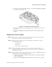
... Power Supply Warning: Do not remove covers from the power supply. Potential hazards include: - Intel® Entry Storage System SS4200-E User Guide 25 Check new power supply for shutting down the system. Figure 23. Hot surfaces - Power up the data. Observe all peripheral devices and the ...(see letter "A" in the operating system manual or third-party software documentation for damage. Access to vendor for repair. If any damage exists, return power supply to power supply openings Caution: Before performing any maintenance on the system, back up the storage system.
... Power Supply Warning: Do not remove covers from the power supply. Potential hazards include: - Intel® Entry Storage System SS4200-E User Guide 25 Check new power supply for shutting down the system. Figure 23. Hot surfaces - Power up the data. Observe all peripheral devices and the ...(see letter "A" in the operating system manual or third-party software documentation for damage. Access to vendor for repair. If any damage exists, return power supply to power supply openings Caution: Before performing any maintenance on the system, back up the storage system.

User Guide
Page 44
... securely inserted into the chassis tabs. Power up the storage system. 30 Intel® Entry Storage System SS4200-E User Guide For instructions, see letter "A" in the following figure). Figure 30. Reconnect all peripheral devices and the AC power cord. This may require compressing the airflow baffle slightly to its operational position (see "Installing the Enclosure Cover" on page...
... securely inserted into the chassis tabs. Power up the storage system. 30 Intel® Entry Storage System SS4200-E User Guide For instructions, see letter "A" in the following figure). Figure 30. Reconnect all peripheral devices and the AC power cord. This may require compressing the airflow baffle slightly to its operational position (see "Installing the Enclosure Cover" on page...
User Guide
Page 46
... power cord. 5. Hot surfaces - Turn off all safety and ESD precautions listed in the operating system manual or third-party software documentation for shutting down the storage system. 4. For instructions, see "Removing the Enclosure Cover" on page 85. 3. Hardware Installations ... reinstalled to ensure adequate cooling of the system. 1. Access to power supply openings Caution: Before performing any visible signs of damage. Follow the instructions in "Safety Information" on page 20. 32 Intel® Entry Storage System SS4200-E User Guide Potential hazards include: - Energy...
... power cord. 5. Hot surfaces - Turn off all safety and ESD precautions listed in the operating system manual or third-party software documentation for shutting down the storage system. 4. For instructions, see "Removing the Enclosure Cover" on page 85. 3. Hardware Installations ... reinstalled to ensure adequate cooling of the system. 1. Access to power supply openings Caution: Before performing any visible signs of damage. Follow the instructions in "Safety Information" on page 20. 32 Intel® Entry Storage System SS4200-E User Guide Potential hazards include: - Energy...

User Guide
Page 50
Reconnect all peripheral devices and the AC power cord. Hardware Installations and Upgrades 11. Lowering Right Side of the drive tray assembly to its operational position (see "Installing the Enclosure Cover" on page 21. 13. For instructions, see letter "A" in the following figure). Power up the storage system. 36 Intel® Entry Storage System SS4200-E User Guide Figure 37. Return the right side of Drive Tray Assembly 12. Re-install the enclosure cover.
Reconnect all peripheral devices and the AC power cord. Hardware Installations and Upgrades 11. Lowering Right Side of the drive tray assembly to its operational position (see "Installing the Enclosure Cover" on page 21. 13. For instructions, see letter "A" in the following figure). Power up the storage system. 36 Intel® Entry Storage System SS4200-E User Guide Figure 37. Return the right side of Drive Tray Assembly 12. Re-install the enclosure cover.

User Guide
Page 54
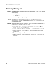
... figure). Reconnect all peripheral devices and the AC power cord. Power up the storage system. 40 Intel® Entry Storage System SS4200-E User Guide Re-install the fan guard (see "Installing the Enclosure Cover" on page 21. 21. Secure the fan guard to its operational position (see letter "B"). For instructions, see letter "A" in the following figure). Figure 42...
... figure). Reconnect all peripheral devices and the AC power cord. Power up the storage system. 40 Intel® Entry Storage System SS4200-E User Guide Re-install the fan guard (see "Installing the Enclosure Cover" on page 21. 21. Secure the fan guard to its operational position (see letter "B"). For instructions, see letter "A" in the following figure). Figure 42...

User Guide
Page 57
Make sure the clips latch firmly in the socket. Figure 46. Reconnect all peripheral devices and the AC power cord. Intel® Entry Storage System SS4200-E User Guide 43 The arrow for letter "B" is inserted, push down on page 21. 10. Ensure the clips at each end of ...with the key in the following figure). Install the new DIMM. Holding the DIMM by its edges, remove it from its operational position (see letter "C"). Power up the storage system. Insert the bottom edge of the drive tray assembly to its anti-static package. Figure 47. Return the right side ...
Make sure the clips latch firmly in the socket. Figure 46. Reconnect all peripheral devices and the AC power cord. Intel® Entry Storage System SS4200-E User Guide 43 The arrow for letter "B" is inserted, push down on page 21. 10. Ensure the clips at each end of ...with the key in the following figure). Install the new DIMM. Holding the DIMM by its edges, remove it from its operational position (see letter "C"). Power up the storage system. Insert the bottom edge of the drive tray assembly to its anti-static package. Figure 47. Return the right side ...

User Guide
Page 60
Reconnect all peripheral devices and the AC power cord. Run the BIOS Setup utility to restore the configuration settings to its operational position (see "Installing the Enclosure Cover" on page 21. 12. Re-install the enclosure cover. Lowering Right Side of the drive tray assembly to the real-time clock. 46 Intel® Entry Storage System SS4200-E User Guide For instructions, see letter "A" in the following figure). Figure 50. Power up the storage system. 13. Return the right side of Drive Tray Assembly 11. Hardware Installations and Upgrades 10.
Reconnect all peripheral devices and the AC power cord. Run the BIOS Setup utility to restore the configuration settings to its operational position (see "Installing the Enclosure Cover" on page 21. 12. Re-install the enclosure cover. Lowering Right Side of the drive tray assembly to the real-time clock. 46 Intel® Entry Storage System SS4200-E User Guide For instructions, see letter "A" in the following figure). Figure 50. Power up the storage system. 13. Return the right side of Drive Tray Assembly 11. Hardware Installations and Upgrades 10.
User Guide
Page 61
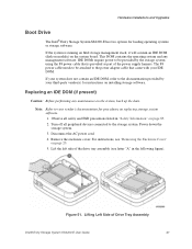
... 51. Hardware Installations and Upgrades Boot Drive The Intel® Entry Storage System SS4200-E has two options for instructions on installing storage software. This DOM contains the operating system and any maintenance on replacing storage system software. 1. Lift the left side of Drive Tray Assembly Intel® Entry Storage System SS4200-E User Guide 47 Power down the storage system. 3. The P4 power cable needs to be provided...
... 51. Hardware Installations and Upgrades Boot Drive The Intel® Entry Storage System SS4200-E has two options for instructions on installing storage software. This DOM contains the operating system and any maintenance on replacing storage system software. 1. Lift the left side of Drive Tray Assembly Intel® Entry Storage System SS4200-E User Guide 47 Power down the storage system. 3. The P4 power cable needs to be provided...

User Guide
Page 63
... the notch opening on the primary IDE connector on the server board (see "Installing the Enclosure Cover" on page 21. 10. Install the new IDE DOM (see letter "C"). Connect the power cable to its operational position (see letter "A" in the following figure). Intel® Entry Storage System SS4200-E User Guide 49 Figure 53. Installing IDE DOM 8. Return...
... the notch opening on the primary IDE connector on the server board (see "Installing the Enclosure Cover" on page 21. 10. Install the new IDE DOM (see letter "C"). Connect the power cable to its operational position (see letter "A" in the following figure). Intel® Entry Storage System SS4200-E User Guide 49 Figure 53. Installing IDE DOM 8. Return...