Instructions
Page 2
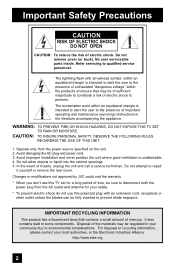
...damaging the AC plug and power cord. 3. Do not remove cover (or back). WARNING: TO PREVENT FIRE OR SHOCK HAZARDS, DO NOT EXPOSE THIS TV SET TO RAIN OR MOISTURE. The exclamation point within the product's enclosure that contains a small amount of electric shock. It also contains lead in the... the risk of mercury. In the event of important operating and maintenance (servicing) instructions in some components. Changes or modifications not approved by JVC could void the warranty. * When you don't use this TV set for a long period of time, be sure to prevent blade exposure.
...damaging the AC plug and power cord. 3. Do not remove cover (or back). WARNING: TO PREVENT FIRE OR SHOCK HAZARDS, DO NOT EXPOSE THIS TV SET TO RAIN OR MOISTURE. The exclamation point within the product's enclosure that contains a small amount of electric shock. It also contains lead in the... the risk of mercury. In the event of important operating and maintenance (servicing) instructions in some components. Changes or modifications not approved by JVC could void the warranty. * When you don't use this TV set for a long period of time, be sure to prevent blade exposure.
Instructions
Page 4
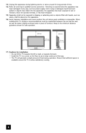
...has been damaged in a corner on the apparatus. 16) Avoid improper installation and never position the unit where good ventilation is available around the TV to allow satisfactory cooling. 4 Keep to the minimum distance guidelines shown for safe operation. 150 mm 200 mm 150 mm 200 mm 50 mm...Refer all servicing to keep cords out of the way. - Ensure that sufficient space is impossible. When installing this apparatus during operation. Install the TV in any way, such as power-supply cord or plug is damaged, liquid has been spilled or objects have fallen into the apparatus, the ...
...has been damaged in a corner on the apparatus. 16) Avoid improper installation and never position the unit where good ventilation is available around the TV to allow satisfactory cooling. 4 Keep to the minimum distance guidelines shown for safe operation. 150 mm 200 mm 150 mm 200 mm 50 mm...Refer all servicing to keep cords out of the way. - Ensure that sufficient space is impossible. When installing this apparatus during operation. Install the TV in any way, such as power-supply cord or plug is damaged, liquid has been spilled or objects have fallen into the apparatus, the ...

Instructions
Page 5
.... • DVD discs, video tapes, laser discs • Broadcast, cable, satellite channels or digital television tuners/converters. These will keep your TV clean. This could cause scratches on TV off XYZ XYZ Caring for the Screen The screen is very dirty, wipe it . For example... Warnings... solvents (like acetone), acidic or alkaline cleansers to wipe down the television, first unplug it down with water. Examples include, but temporary ghost image on your viewing pattern. If you wish to the screen. TV on the screen surface and image distortions. 5 Wipe the set gently...
.... • DVD discs, video tapes, laser discs • Broadcast, cable, satellite channels or digital television tuners/converters. These will keep your TV clean. This could cause scratches on TV off XYZ XYZ Caring for the Screen The screen is very dirty, wipe it . For example... Warnings... solvents (like acetone), acidic or alkaline cleansers to wipe down the television, first unplug it down with water. Examples include, but temporary ghost image on your viewing pattern. If you wish to the screen. TV on the screen surface and image distortions. 5 Wipe the set gently...
Instructions
Page 6
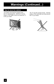
Warnings (Continued...) How to tilt up or down . Hold the TV at the bottom in the middle, and do not allow the TV to move the cabinet Your fingers may fall causing injuries. Hold the bottom of the stand with your hand and tilt the TV up or down . 6 The TV may become trapped under the TV, causing injuries.
Warnings (Continued...) How to tilt up or down . Hold the TV at the bottom in the middle, and do not allow the TV to move the cabinet Your fingers may fall causing injuries. Hold the bottom of the stand with your hand and tilt the TV up or down . 6 The TV may become trapped under the TV, causing injuries.
Instructions
Page 7
... Set Lock Code 44 Auto Demo 45 Illumination 45 Language 45 Closed Caption 46 Auto Shut Off 48 XDS ID 48 Noise Muting 49 Front Panel Lock 49 V1 Smart Input 50 Video Input Label 50 Position Adjustment 51 Power Indicator 51 Video-1 Monitor Out 51 Digital-In 52 Digital-In... Function 59 Index 59 Twin 59 Freeze 60 Swap 60 Select 60 Power 61 Number Buttons 61 Tune 61 Input 61 TheaterPro D6500K 61 Return+/TV 62 Sound 62 Muting 63 Video Status 63 Natural Cinema 63 Sleep Timer 64 ML/MTS 64 Display 65 C.C 65 Channel 65 Volume 65 Favorite...
... Set Lock Code 44 Auto Demo 45 Illumination 45 Language 45 Closed Caption 46 Auto Shut Off 48 XDS ID 48 Noise Muting 49 Front Panel Lock 49 V1 Smart Input 50 Video Input Label 50 Position Adjustment 51 Power Indicator 51 Video-1 Monitor Out 51 Digital-In 52 Digital-In... Function 59 Index 59 Twin 59 Freeze 60 Swap 60 Select 60 Power 61 Number Buttons 61 Tune 61 Input 61 TheaterPro D6500K 61 Return+/TV 62 Sound 62 Muting 63 Video Status 63 Natural Cinema 63 Sleep Timer 64 ML/MTS 64 Display 65 C.C 65 Channel 65 Volume 65 Favorite...
Instructions
Page 9
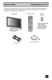
... the following items. In addition to this guide, your purchase of a JVC LCD Flat Television. RF Cable × 2 2-WAY SPLITTER Two Way Splitter x 1 9 Before you begin setting up your new television, please check to make sure you for your television box should include: 1 Television 1 Remote Control TV CATV VCR DVD POWER ASPECT MULTI SCREEN TWIN INDEX SELECT SLEEP...
... the following items. In addition to this guide, your purchase of a JVC LCD Flat Television. RF Cable × 2 2-WAY SPLITTER Two Way Splitter x 1 9 Before you begin setting up your new television, please check to make sure you for your television box should include: 1 Television 1 Remote Control TV CATV VCR DVD POWER ASPECT MULTI SCREEN TWIN INDEX SELECT SLEEP...
Instructions
Page 10
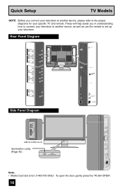
... i.LINK IN/OUT S400(TS) OPTICAL OUT Digital Audio xD-Picture Card MEMORY STICK PUSH-OPEN SD/ MMC Close door when using media cards. Rear Panel Diagram INPUT 1 INPUT 2 INPUT 3 S-VIDEO VIDEO OVER R - L S-VIDEO VIDEO OVER R - L VIDEO R - AUDIO - AUDIO - AUDIO ... INPUT MENU/OK < CHANNEL > OPERATE + VOLUME - L L S-VIDEO VIDEO R - Quick Setup TV Models NOTE: Before you in understanding how to connect your television to another device, please refer to set up your specific TV and remote. AUDIO - L VIDEO R - To open the door, gently press the "PUSH OPEN"....
... i.LINK IN/OUT S400(TS) OPTICAL OUT Digital Audio xD-Picture Card MEMORY STICK PUSH-OPEN SD/ MMC Close door when using media cards. Rear Panel Diagram INPUT 1 INPUT 2 INPUT 3 S-VIDEO VIDEO OVER R - L S-VIDEO VIDEO OVER R - L VIDEO R - AUDIO - AUDIO - AUDIO ... INPUT MENU/OK < CHANNEL > OPERATE + VOLUME - L L S-VIDEO VIDEO R - Quick Setup TV Models NOTE: Before you in understanding how to connect your television to another device, please refer to set up your specific TV and remote. AUDIO - L VIDEO R - To open the door, gently press the "PUSH OPEN"....
Instructions
Page 11
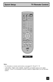
... CHANNEL SUB LIGHT MUTING CH GUIDE VOL OK VOL CH MENU VCR CHANNEL PREV NEXT BACK VCR DVD POWER TV VCR REW PLAY FF REC STOP PAUSE OPEN CLOSE STILL PAUSE RM-C14G RM-C14G Notes: • For information on remote control buttons, see pages ...59 - 69 and 73 - 78. • i.LINK MENU, TIMER, SUB CHANNEL, FAVORITE and GUIDE buttons are for digital channels. Quick Setup TV Remote Control TV CATV VCR DVD POWER ASPECT MULTI SCREEN TWIN INDEX SELECT SLEEP FREEZE SWAP ML/MTS DISPLAY + INPUT 123 D/A 4 5 6 i.LINK MENU 7 TIMER TUNE THEATER FAVORITE...
... CHANNEL SUB LIGHT MUTING CH GUIDE VOL OK VOL CH MENU VCR CHANNEL PREV NEXT BACK VCR DVD POWER TV VCR REW PLAY FF REC STOP PAUSE OPEN CLOSE STILL PAUSE RM-C14G RM-C14G Notes: • For information on remote control buttons, see pages ...59 - 69 and 73 - 78. • i.LINK MENU, TIMER, SUB CHANNEL, FAVORITE and GUIDE buttons are for digital channels. Quick Setup TV Remote Control TV CATV VCR DVD POWER ASPECT MULTI SCREEN TWIN INDEX SELECT SLEEP FREEZE SWAP ML/MTS DISPLAY + INPUT 123 D/A 4 5 6 i.LINK MENU 7 TIMER TUNE THEATER FAVORITE...

Instructions
Page 12
... other hand to hold the edge of the panel and slowly adjust the direction of the TV screen 5° up or down and 20° to the left or right. These illustrations are different. Using the stand This TV comes with one hand, use your new television right away. You can be used to... the left or right. Tilt the TV up , 10° down While holding the bottom of the stand with the basic information...
... other hand to hold the edge of the panel and slowly adjust the direction of the TV screen 5° up or down and 20° to the left or right. These illustrations are different. Using the stand This TV comes with one hand, use your new television right away. You can be used to... the left or right. Tilt the TV up , 10° down While holding the bottom of the stand with the basic information...
Instructions
Page 13
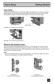
... are connection terminals behind the covers on the back of the stand. Illustration of LT-32X776 and LT-26X776 Illustration of the covers against the TV and insert the hooks. The covers can be removed by removing the hooks. When replacing the covers, place the side of LT-37X776 and LT... from the stand. Note: • Leave the terminal covers off if they do not fit properly. After putting the cables in the back of the TV.
... are connection terminals behind the covers on the back of the stand. Illustration of LT-32X776 and LT-26X776 Illustration of the covers against the TV and insert the hooks. The covers can be removed by removing the hooks. When replacing the covers, place the side of LT-37X776 and LT... from the stand. Note: • Leave the terminal covers off if they do not fit properly. After putting the cables in the back of the TV.
Instructions
Page 14
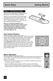
... arrows and are turning on programming your VCR, DVD, and/or cable box/satellite receiver may have to be used with JVC's onscreen menu system. If this is set to TV. Slide the cover on and off by at the top right corner of the remote control. The top and bottom buttons... use the onscreen menus, press the MENU button. MUTING CH GUIDE VOL OK VOL CH MENU VCR CHANNEL BACK VCR DVD Basic Operation Turn the television on the back of the remote can operate your remote control, you need to 31 for basic operation of five channels per second. Quick Setup...
... arrows and are turning on programming your VCR, DVD, and/or cable box/satellite receiver may have to be used with JVC's onscreen menu system. If this is set to TV. Slide the cover on and off by at the top right corner of the remote control. The top and bottom buttons... use the onscreen menus, press the MENU button. MUTING CH GUIDE VOL OK VOL CH MENU VCR CHANNEL BACK VCR DVD Basic Operation Turn the television on the back of the remote can operate your remote control, you need to 31 for basic operation of five channels per second. Quick Setup...
Instructions
Page 15
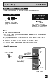
...) Coaxial Cable (Attachment) IN OUT OUT Two-way Splitter (Attachment) /ADTSIGCITAL CABLE IN TV Rear Panel DIGITAL-IN 15 Quick Setup Connections Step 3 - S-Video Cable Component Cables Composite Cables Audio Cables Used to make these diagrams and the television does not work properly, contact your devices, plug the power cord into the nearest...
...) Coaxial Cable (Attachment) IN OUT OUT Two-way Splitter (Attachment) /ADTSIGCITAL CABLE IN TV Rear Panel DIGITAL-IN 15 Quick Setup Connections Step 3 - S-Video Cable Component Cables Composite Cables Audio Cables Used to make these diagrams and the television does not work properly, contact your devices, plug the power cord into the nearest...
Instructions
Page 16
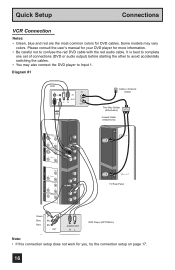
... Two-Way Splitter IN (Attachment) OUT OUT Coaxial Cable (Attachment) INPUT 1 S-VIDEO VIDEO R - AUDIO - L S-VIDEO VIDEO R - AUDIO - L Y Pr Pb R - AUDIO - L ATSC / DIGITAL CABLE IN TV Rear Panel DIGITAL-IN CABLE CARD Green Blue Red AUDIO OUT Y PB PR R L OUT AUDIO OUT R L DVD Player (OPTIONAL) i.LINK IN/OUT S400(TS) Note: • If...
... Two-Way Splitter IN (Attachment) OUT OUT Coaxial Cable (Attachment) INPUT 1 S-VIDEO VIDEO R - AUDIO - L S-VIDEO VIDEO R - AUDIO - L Y Pr Pb R - AUDIO - L ATSC / DIGITAL CABLE IN TV Rear Panel DIGITAL-IN CABLE CARD Green Blue Red AUDIO OUT Y PB PR R L OUT AUDIO OUT R L DVD Player (OPTIONAL) i.LINK IN/OUT S400(TS) Note: • If...
Instructions
Page 17
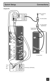
L VIDEO R - AUDIO - AUDIO - L INPUT 3 Connections Cable or Antenna Output IN OUT OUT Two-Way Splitter IN Two-Way Splitter OUT OUT (Attachment) Coaxial Cable (Attachment) (7V5HΩF/UHF) ATSC / DIGITAL CABLE IN TV Rear Panel DIGITAL-IN DIGITAL IN AUDIO INPUT 1 COMPONENT Green Blue Red AUDIO OUT Y PB PR R L OUT AUDIO OUT R L DVD Player (OPTIONAL) CABLE CARD 17 AUDIO - L Y Pr Pb R - L S-VIDEO VIDEO R - Quick Setup Diagram #2 VCR IN OUT V LR IN OUT OR INPUT 1 INPUT 2 S-VIDEO VIDEO R - AUDIO -
L VIDEO R - AUDIO - AUDIO - L INPUT 3 Connections Cable or Antenna Output IN OUT OUT Two-Way Splitter IN Two-Way Splitter OUT OUT (Attachment) Coaxial Cable (Attachment) (7V5HΩF/UHF) ATSC / DIGITAL CABLE IN TV Rear Panel DIGITAL-IN DIGITAL IN AUDIO INPUT 1 COMPONENT Green Blue Red AUDIO OUT Y PB PR R L OUT AUDIO OUT R L DVD Player (OPTIONAL) CABLE CARD 17 AUDIO - L Y Pr Pb R - L S-VIDEO VIDEO R - Quick Setup Diagram #2 VCR IN OUT V LR IN OUT OR INPUT 1 INPUT 2 S-VIDEO VIDEO R - AUDIO -

Instructions
Page 18
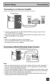
...jack into the RIGHT AUDIO IN on the television's side panel. AUDIO - AUD 1) Connect a yellow composite cable from the camcorder VIDEO OUT, into the VIDEO IN on the back of the TV, OR connect an S-Video cable from the camcorder to the back of the TV. 2) Connect a white cable from the ... camcorder RIGHT AUDIO OUT, into the headphone jack on the back of the TV. Connect it will have only one AUDIO OUT. TV Side Panel 18 Quick Setup Connections Connecting to a Camcorder You can connect a pair of headphones to the television using the input jacks located on the back of the...
...jack into the RIGHT AUDIO IN on the television's side panel. AUDIO - AUD 1) Connect a yellow composite cable from the camcorder VIDEO OUT, into the VIDEO IN on the back of the TV, OR connect an S-Video cable from the camcorder to the back of the TV. 2) Connect a white cable from the ... camcorder RIGHT AUDIO OUT, into the headphone jack on the back of the TV. Connect it will have only one AUDIO OUT. TV Side Panel 18 Quick Setup Connections Connecting to a Camcorder You can connect a pair of headphones to the television using the input jacks located on the back of the...
Instructions
Page 19
...not viewing images coming from the composite video input terminal. • No signal will be outputted. Connecting to an External Amplifier TV Rear Panel S-VIDEO VIDEO OVER RR - AUDIO - L L Speaker Amplifier Speaker AUDIOMOUNITTOR / REC OUT 1) Connect a white cable from the LEFT AUDIO ...OUTPUT on the amplifier. L L TV Rear Panel VCR IN OUT OR R L V IN OUT Notes: • When you are viewing images from the RIGHT AUDIO OUTPUT on the amplifier. 2) ...
...not viewing images coming from the composite video input terminal. • No signal will be outputted. Connecting to an External Amplifier TV Rear Panel S-VIDEO VIDEO OVER RR - AUDIO - L L Speaker Amplifier Speaker AUDIOMOUNITTOR / REC OUT 1) Connect a white cable from the LEFT AUDIO ...OUTPUT on the amplifier. L L TV Rear Panel VCR IN OUT OR R L V IN OUT Notes: • When you are viewing images from the RIGHT AUDIO OUTPUT on the amplifier. 2) ...
Instructions
Page 20
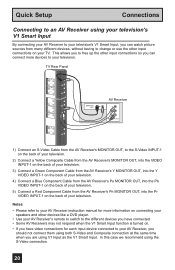
...AV Receiver's Y MONITOR OUT, into the Y VIDEO INPUT-1 on the back of your television. 4) Connect a Blue Component Cable from the AV Receiver's PR MONITOR OUT, into the Pr VIDEO INPUT-1 on your TV. In this case we recommend using the S-Video connection. 20 This allows you to ... a Red Component Cable from the AV Receiver's PB MONITOR OUT, into the Pb VIDEO INPUT-1 on the back of your television. AUDIO - AUDIO - TV Rear Panel INPUT 1 INPUT 2 INPUT 3 S-VIDEO VIDEO OVER R - L S-VIDEO VIDEO OVER R - AUDIO - Notes: • Please refer to your AV Receiver instruction manual for...
...AV Receiver's Y MONITOR OUT, into the Y VIDEO INPUT-1 on the back of your television. 4) Connect a Blue Component Cable from the AV Receiver's PR MONITOR OUT, into the Pr VIDEO INPUT-1 on your TV. In this case we recommend using the S-Video connection. 20 This allows you to ... a Red Component Cable from the AV Receiver's PB MONITOR OUT, into the Pb VIDEO INPUT-1 on the back of your television. AUDIO - AUDIO - TV Rear Panel INPUT 1 INPUT 2 INPUT 3 S-VIDEO VIDEO OVER R - L S-VIDEO VIDEO OVER R - AUDIO - Notes: • Please refer to your AV Receiver instruction manual for...
Instructions
Page 21
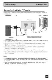
... the Initial Setup menu to digitally connect the television with the picture signal of your TV in their digital form. INPUT 2 ATSC / DIGITAL CABLE IN DTV Decoder DIGITAL OUT AUDIO OUT LR INPUT 3 TV Rear Panel R - Quick Setup Connections Connecting to a Digital TV Receiver By connecting a Digital TV Receiver, high definition pictures can be displayed on...
... the Initial Setup menu to digitally connect the television with the picture signal of your TV in their digital form. INPUT 2 ATSC / DIGITAL CABLE IN DTV Decoder DIGITAL OUT AUDIO OUT LR INPUT 3 TV Rear Panel R - Quick Setup Connections Connecting to a Digital TV Receiver By connecting a Digital TV Receiver, high definition pictures can be displayed on...
Instructions
Page 22
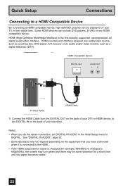
... -top box, DVD player, A/V receiver or an audio and/or video monitor, such as a digital television (DTV). HDMI Compatible Device ATSC / DIGITAL CABLE IN DIGITAL OUT AUDIO OUT LR DIGITAL-IN CABLE CARD TV Rear Panel HDMI Cable 1) Connect the HDMI Cable from the DIGITAL OUT on the back of your... television. Notes: • When you have connected when it is connected to the HDMI. • If ...
... -top box, DVD player, A/V receiver or an audio and/or video monitor, such as a digital television (DTV). HDMI Compatible Device ATSC / DIGITAL CABLE IN DIGITAL OUT AUDIO OUT LR DIGITAL-IN CABLE CARD TV Rear Panel HDMI Cable 1) Connect the HDMI Cable from the DIGITAL OUT on the back of your... television. Notes: • When you have connected when it is connected to the HDMI. • If ...
Instructions
Page 24
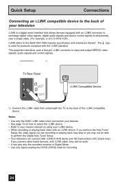
TV Rear Panel i.LINK IN/OUT S400(TS) OPTICAL OUT Digital Audio i.LINK Compatible Device 1) Connect the i.LINK cable from underneath the TV to input and output MPEG2 video signals, audio signals and control signals. The logo is a digital serial interface that allows devices equipped ... digital audio signals and device control signals bi-directionally over a single cable. (For example, a JVC D-VHS VCR). If you may not be able to perform the Digital Auto Tuner Setup. • Your television can play only the recorded contents in Digital Mode. • Use only tapes bearing the DVHS ...
TV Rear Panel i.LINK IN/OUT S400(TS) OPTICAL OUT Digital Audio i.LINK Compatible Device 1) Connect the i.LINK cable from underneath the TV to input and output MPEG2 video signals, audio signals and control signals. The logo is a digital serial interface that allows devices equipped ... digital audio signals and device control signals bi-directionally over a single cable. (For example, a JVC D-VHS VCR). If you may not be able to perform the Digital Auto Tuner Setup. • Your television can play only the recorded contents in Digital Mode. • Use only tapes bearing the DVHS ...


