Instructions
Page 7
... Illumination 45 Language 45 Closed Caption 46 Auto Shut Off 48 XDS ID 48 Noise Muting 49 Front Panel Lock 49 V1 Smart Input 50 Video Input Label 50 Position Adjustment 51 Power Indicator 51 Video-1 Monitor Out 51 Digital-In 52 Digital-In Audio 52 Picture Adjust 53 Picture Settings 53 Adjust... 59 Twin 59 Freeze 60 Swap 60 Select 60 Power 61 Number Buttons 61 Tune 61 Input 61 TheaterPro D6500K 61 Return+/TV 62 Sound 62 Muting 63 Video Status 63 Natural Cinema 63 Sleep Timer 64 ML/MTS 64 Display 65 C.C 65 Channel 65 Volume 65 Favorite 66 Aspect 67 Aspect...
... Illumination 45 Language 45 Closed Caption 46 Auto Shut Off 48 XDS ID 48 Noise Muting 49 Front Panel Lock 49 V1 Smart Input 50 Video Input Label 50 Position Adjustment 51 Power Indicator 51 Video-1 Monitor Out 51 Digital-In 52 Digital-In Audio 52 Picture Adjust 53 Picture Settings 53 Adjust... 59 Twin 59 Freeze 60 Swap 60 Select 60 Power 61 Number Buttons 61 Tune 61 Input 61 TheaterPro D6500K 61 Return+/TV 62 Sound 62 Muting 63 Video Status 63 Natural Cinema 63 Sleep Timer 64 ML/MTS 64 Display 65 C.C 65 Channel 65 Volume 65 Favorite 66 Aspect 67 Aspect...

Instructions
Page 8
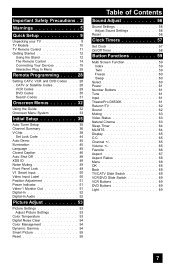
Table of Contents Digital Setup 70 Digital Setup 70 Antenna Level 70 Digital Sound 71 Aspect Ratio 71 Cable Card Application 72 i.LINK Auto Play 72 Software Update 72 Digital Button Functions . . . 73 Digital CH D/A (Digital/Analog) . . . . . 73 Sub ... Viewer 79 Readable Media Card 79 Supported Card Media 79 How to insert Media Card 80 How to operate Media Card Viewer . . . . 81 PHOTO 82 VIDEO 82 FILE 83 Operation Note 84 Specifications for Media Card Viewer . . 85 OSD Information 86 Weak Signal 86 No Program 86 Cable Card Information . . . . 87...
Table of Contents Digital Setup 70 Digital Setup 70 Antenna Level 70 Digital Sound 71 Aspect Ratio 71 Cable Card Application 72 i.LINK Auto Play 72 Software Update 72 Digital Button Functions . . . 73 Digital CH D/A (Digital/Analog) . . . . . 73 Sub ... Viewer 79 Readable Media Card 79 Supported Card Media 79 How to insert Media Card 80 How to operate Media Card Viewer . . . . 81 PHOTO 82 VIDEO 82 FILE 83 Operation Note 84 Specifications for Media Card Viewer . . 85 OSD Information 86 Weak Signal 86 No Program 86 Cable Card Information . . . . 87...
Instructions
Page 9
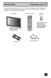
... SELECT SLEEP FREEZE SWAP ML/MTS DISPLAY + INPUT 123 D/A 4 5 6 i.LINK MENU 7 TIMER TUNE THEATER FAVORITE PRO C.C. Before you have all of a JVC LCD Flat Television. RF Cable × 2 2-WAY SPLITTER Two Way Splitter x 1 9 SOUND 8 0 VIDEO STATUS NATURAL CINEMA 9 RETURN+ TV SUB CHANNEL SUB LIGHT MUTING CH GUIDE VOL OK VOL CH MENU VCR CHANNEL PREV NEXT...
... SELECT SLEEP FREEZE SWAP ML/MTS DISPLAY + INPUT 123 D/A 4 5 6 i.LINK MENU 7 TIMER TUNE THEATER FAVORITE PRO C.C. Before you have all of a JVC LCD Flat Television. RF Cable × 2 2-WAY SPLITTER Two Way Splitter x 1 9 SOUND 8 0 VIDEO STATUS NATURAL CINEMA 9 RETURN+ TV SUB CHANNEL SUB LIGHT MUTING CH GUIDE VOL OK VOL CH MENU VCR CHANNEL PREV NEXT...
Instructions
Page 11
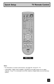
... CATV VCR DVD POWER ASPECT MULTI SCREEN TWIN INDEX SELECT SLEEP FREEZE SWAP ML/MTS DISPLAY + INPUT 123 D/A 4 5 6 i.LINK MENU 7 TIMER TUNE THEATER FAVORITE PRO C.C. SOUND 8 0 VIDEO STATUS NATURAL CINEMA 9 RETURN+ TV SUB CHANNEL SUB LIGHT MUTING CH GUIDE VOL OK VOL CH MENU VCR CHANNEL PREV NEXT BACK VCR DVD POWER...
... CATV VCR DVD POWER ASPECT MULTI SCREEN TWIN INDEX SELECT SLEEP FREEZE SWAP ML/MTS DISPLAY + INPUT 123 D/A 4 5 6 i.LINK MENU 7 TIMER TUNE THEATER FAVORITE PRO C.C. SOUND 8 0 VIDEO STATUS NATURAL CINEMA 9 RETURN+ TV SUB CHANNEL SUB LIGHT MUTING CH GUIDE VOL OK VOL CH MENU VCR CHANNEL PREV NEXT BACK VCR DVD POWER...

Instructions
Page 18
... located on the side of the television. TV Rear Panel CAMCORDER OR INPUT 2 INPUT 1 S-VIDEO VIDEO R - L INPUT 3 VIDEO R - AUD 1) Connect a yellow composite cable from the camcorder VIDEO OUT, into the VIDEO IN on the back of the TV, OR connect an S-Video cable from the camcorder RIGHT AUDIO ...sound model it to the back of the TV. 2) Connect a white cable from the camcorder LEFT AUDIO OUT, into the LEFT AUDIO IN on the back of the TV. 3) Connect a red cable from the camcorder to the LEFT AUDIO IN on the television's side panel. TV Side Panel 18 AUDIO - L S-VIDEO VIDEO...
... located on the side of the television. TV Rear Panel CAMCORDER OR INPUT 2 INPUT 1 S-VIDEO VIDEO R - L INPUT 3 VIDEO R - AUD 1) Connect a yellow composite cable from the camcorder VIDEO OUT, into the VIDEO IN on the back of the TV, OR connect an S-Video cable from the camcorder RIGHT AUDIO ...sound model it to the back of the TV. 2) Connect a white cable from the camcorder LEFT AUDIO OUT, into the LEFT AUDIO IN on the back of the TV. 3) Connect a red cable from the camcorder to the LEFT AUDIO IN on the television's side panel. TV Side Panel 18 AUDIO - L S-VIDEO VIDEO...
Instructions
Page 19
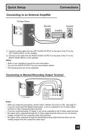
...• You can use AUDIO OUTPUT for your home theater system. • DVI analog sound can not be outputted to the S-Video output terminal. • No signal will be outputted through the S-Video output terminal when you are viewing images from the RIGHT AUDIO OUTPUT on the back of ...the TV to ON. Connecting to an External Amplifier TV Rear Panel S-VIDEO VIDEO OVER RR - AUDIO - See page 51. • If you are receiving ATSC/Digital Cable signal, it can be outputted to the S-Video output terminal or Video (composite video) terminal. • If you are receiving Analog TV signal, ...
...• You can use AUDIO OUTPUT for your home theater system. • DVI analog sound can not be outputted to the S-Video output terminal. • No signal will be outputted through the S-Video output terminal when you are viewing images from the RIGHT AUDIO OUTPUT on the back of ...the TV to ON. Connecting to an External Amplifier TV Rear Panel S-VIDEO VIDEO OVER RR - AUDIO - See page 51. • If you are receiving ATSC/Digital Cable signal, it can be outputted to the S-Video output terminal or Video (composite video) terminal. • If you are receiving Analog TV signal, ...

Instructions
Page 34
...INITIAL SETUP 04 CLOCK / TIMERS PREVIOUS SET CLOCK ON / OFF TIMER NEXT PAGE SELECT OPERATE MENU EXIT CLOCK/TIMERS INITIAL SETUP PREVIOUS VIDEO-1 MONITOR OUT DIGITAL-IN DIGITAL-IN AUDIO OFF SIZE1 DIGITAL NEXT PAGE SELECT OPERATE (1/5) MENU EXIT INITIAL SETUP 01 INITIAL SETUP PREVIOUS ... NEXT PAGE SELECT OPERATE (5/5) MENU EXIT INITIAL SETUP 05 RESET NEXT PAGE SELECT OPERATE MENU EXIT SOUND ADJUST INITIAL SETUP PREVIOUS NOISE MUTING FRONT PANEL LOCK V1 SMART INPUT VIDEO INPUT LABEL POSITION ADJUSTMENT POWER INDICATOR ON OFF ON LOW NEXT PAGE SELECT OPERATE (2/5) MENU EXIT ...
...INITIAL SETUP 04 CLOCK / TIMERS PREVIOUS SET CLOCK ON / OFF TIMER NEXT PAGE SELECT OPERATE MENU EXIT CLOCK/TIMERS INITIAL SETUP PREVIOUS VIDEO-1 MONITOR OUT DIGITAL-IN DIGITAL-IN AUDIO OFF SIZE1 DIGITAL NEXT PAGE SELECT OPERATE (1/5) MENU EXIT INITIAL SETUP 01 INITIAL SETUP PREVIOUS ... NEXT PAGE SELECT OPERATE (5/5) MENU EXIT INITIAL SETUP 05 RESET NEXT PAGE SELECT OPERATE MENU EXIT SOUND ADJUST INITIAL SETUP PREVIOUS NOISE MUTING FRONT PANEL LOCK V1 SMART INPUT VIDEO INPUT LABEL POSITION ADJUSTMENT POWER INDICATOR ON OFF ON LOW NEXT PAGE SELECT OPERATE (2/5) MENU EXIT ...
Instructions
Page 52
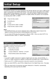
See page 71. • When you select AUTO, the television will select "SIZE1" or "SIZE2" automatically. This option adjusts the position when a 480p picture signal is capable of analog audio and digital video, choose ANALOG. • Refer to your DTV or HDMI component is being displayed on the ... position can only be displayed when a 480p picture signal is input to the Digital-In terminal and the picture is being displayed on Digital Sound in the INITIAL SETUP menu when a 480p picture signal is 480p for more information. • When you select AUTO, the televison will ...
See page 71. • When you select AUTO, the television will select "SIZE1" or "SIZE2" automatically. This option adjusts the position when a 480p picture signal is capable of analog audio and digital video, choose ANALOG. • Refer to your DTV or HDMI component is being displayed on the ... position can only be displayed when a 480p picture signal is input to the Digital-In terminal and the picture is being displayed on Digital Sound in the INITIAL SETUP menu when a 480p picture signal is 480p for more information. • When you select AUTO, the televison will ...

Instructions
Page 68
...panel and choose a mode by using the MENU button on using the CHANNEL +/- Press MENU to activate the onscreen menu system. • See individual topics like "Sound... Adjust" for specific information on the side of the TV instead of the onscreen menus. buttons ( √ OPERATE ® ). • "SLIM" can not be dispalyed when the signal is different from their broadcast or recorded program. OK This button confirms your HDMI device when you to access JVC...are in FULL aspect mode, it has VIDEO STATUS and ASPECT menus. If the television receives a 4:3 signal from your HDMI ...
...panel and choose a mode by using the MENU button on using the CHANNEL +/- Press MENU to activate the onscreen menu system. • See individual topics like "Sound... Adjust" for specific information on the side of the TV instead of the onscreen menus. buttons ( √ OPERATE ® ). • "SLIM" can not be dispalyed when the signal is different from their broadcast or recorded program. OK This button confirms your HDMI device when you to access JVC...are in FULL aspect mode, it has VIDEO STATUS and ASPECT menus. If the television receives a 4:3 signal from your HDMI ...
Instructions
Page 81
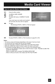
... VIEWER To enter To select SD Card or COMPACT FLASH card SELECT CARD, AND PRESS OK SD Card COMPACT FLASH If you insert. • The sound from the media card can not be changed. • Onscreen language is linked to LANGUAGE in the Initial Setup Menu. • When the media card... viewer function is used . • The following PHOTO, VIDEO or FILE will appear SELECT ONE, AND PRESS OK PHOTO VIDEO FILE √® To select PHOTO, VIDEO or FILE (Continue to page 82 or 83) Notes: • The above screen will not appear. When...
... VIEWER To enter To select SD Card or COMPACT FLASH card SELECT CARD, AND PRESS OK SD Card COMPACT FLASH If you insert. • The sound from the media card can not be changed. • Onscreen language is linked to LANGUAGE in the Initial Setup Menu. • When the media card... viewer function is used . • The following PHOTO, VIDEO or FILE will appear SELECT ONE, AND PRESS OK PHOTO VIDEO FILE √® To select PHOTO, VIDEO or FILE (Continue to page 82 or 83) Notes: • The above screen will not appear. When...

Instructions
Page 88
... the channels have been programmed. The color quality is no picture or sound • The antenna could be disconnected. • The input mode could... such as a computer, another TV or VCR. If you purchased the television. Remote control is snowy (image noise) • Your antenna may be ... the MTS settings are still working . See page 53. • The Video Status mode may be too far from a high-wattage appliance, like a hairdryer...the condition. It is possible that there is a problem, contact the JVC Service Center where you think that external noise or interference is locked. ...
... the channels have been programmed. The color quality is no picture or sound • The antenna could be disconnected. • The input mode could... such as a computer, another TV or VCR. If you purchased the television. Remote control is snowy (image noise) • Your antenna may be ... the MTS settings are still working . See page 53. • The Video Status mode may be too far from a high-wattage appliance, like a hairdryer...the condition. It is possible that there is a problem, contact the JVC Service Center where you think that external noise or interference is locked. ...

Instructions
Page 92
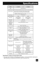
Specifications Model LT-26X776 LT-32X776 Type LCD Flat Television Reception Format NTSC, BTSC System (Multi-Channel Sound) ATSC Terrestrial, Digital Cable Reception Range VHF 2 to 13, UHF 14 to "unpacking your TV set. AC 120V, 60 Hz 139W 26 inch / 64.8 cm ... 10W + 10W Speakers 6.6 cm round x 2 Antenna Terminal (VHF/UHF, ATSC/DIGITAL CABLE IN) External Input Jacks Component Input Jack 75 ohms (VHF/UHF)(F-type connector) Video: 1 Vp-p, 75 ohms Audio: 500 mVrms (-4dBs) high impedance Y: 1Vp-p positive, 75 ohms (negative sync provided) Pb/Pr: 0.7 Vp-p 75 ohms...
Specifications Model LT-26X776 LT-32X776 Type LCD Flat Television Reception Format NTSC, BTSC System (Multi-Channel Sound) ATSC Terrestrial, Digital Cable Reception Range VHF 2 to 13, UHF 14 to "unpacking your TV set. AC 120V, 60 Hz 139W 26 inch / 64.8 cm ... 10W + 10W Speakers 6.6 cm round x 2 Antenna Terminal (VHF/UHF, ATSC/DIGITAL CABLE IN) External Input Jacks Component Input Jack 75 ohms (VHF/UHF)(F-type connector) Video: 1 Vp-p, 75 ohms Audio: 500 mVrms (-4dBs) high impedance Y: 1Vp-p positive, 75 ohms (negative sync provided) Pb/Pr: 0.7 Vp-p 75 ohms...
Instructions
Page 93
... sync provided) Pb/Pr: 0.7 Vp-p 75 ohms Y: 1Vp-p positive, 75 ohms (negative sync provided) C: 0.286 Vp-p (burst signal), 75 ohms Video: 1Vp-p, 75ohms Y: 1Vp-p positive, 75 ohms (negative sync provided) C: 0.286 Vp-p (burst signal), 75 ohms Audio: 250mVrms (-10dBs) Fs-18dB ...to "unpacking your TV", page 9 Specifications subject to : http://software.jvc.com/opensource/lnx/DP/04_AtscCC/download.html 93 Specifications Model LT-37X776 LT-40X776 Type LCD Flat Television Reception Format NTSC, BTSC System (Multi-Channel Sound) ATSC Terrestrial, Digital Cable Reception Range VHF 2 to 13, UHF...
... sync provided) Pb/Pr: 0.7 Vp-p 75 ohms Y: 1Vp-p positive, 75 ohms (negative sync provided) C: 0.286 Vp-p (burst signal), 75 ohms Video: 1Vp-p, 75ohms Y: 1Vp-p positive, 75 ohms (negative sync provided) C: 0.286 Vp-p (burst signal), 75 ohms Audio: 250mVrms (-10dBs) Fs-18dB ...to "unpacking your TV", page 9 Specifications subject to : http://software.jvc.com/opensource/lnx/DP/04_AtscCC/download.html 93 Specifications Model LT-37X776 LT-40X776 Type LCD Flat Television Reception Format NTSC, BTSC System (Multi-Channel Sound) ATSC Terrestrial, Digital Cable Reception Range VHF 2 to 13, UHF...


