
Instruction Manual
Page 6
... REC PAUSE • Operating buttons for speakers and subwoofer output level and D. buttons (36 - 40) 9 TV VOLUME +/- Parts identification 1 DVR DVD A/V CONTROL STANDBY/ON RECEIVER TEST *FRONT L *FRONT R AUDIO 1 2 3 EFFECT *CENTER *SUBWFR DVR/DVD 2 4 5 6 p C.TONE *SURR L *SURR R VCR 7 8 9 3 4 *D.EQ FREQ*S BACK L ...DVD mode selector (37, 40) 2 • Numeric buttons (26, 36 - 40) 1 - 10, 0, +10, 100+ • Adjusting buttons for JVC products ONLY), set the mode selector (1) to "DVR." • When operating a DVD player, set to "DVD." 2 TONE, SURR L, SURR R, D. ...
... REC PAUSE • Operating buttons for speakers and subwoofer output level and D. buttons (36 - 40) 9 TV VOLUME +/- Parts identification 1 DVR DVD A/V CONTROL STANDBY/ON RECEIVER TEST *FRONT L *FRONT R AUDIO 1 2 3 EFFECT *CENTER *SUBWFR DVR/DVD 2 4 5 6 p C.TONE *SURR L *SURR R VCR 7 8 9 3 4 *D.EQ FREQ*S BACK L ...DVD mode selector (37, 40) 2 • Numeric buttons (26, 36 - 40) 1 - 10, 0, +10, 100+ • Adjusting buttons for JVC products ONLY), set the mode selector (1) to "DVR." • When operating a DVD player, set to "DVD." 2 TONE, SURR L, SURR R, D. ...

Instruction Manual
Page 7
... OUT CAUTION:SPEAKER IMPEDANCE 6 -16 7 1 Power cord (11) 2 COMPONENT VIDEO (Y, PB, PR) jacks (8, 9) VIDEO IN, DVR/DVD IN, MONITOR OUT 3 AV IN/OUT terminals (7) TV, VCR, DVR/DVD 4 DIGITAL IN terminals (10) • Coaxial: 1(DVR/DVD) • Optical: 2(VIDEO) 5 ANTENNA terminals (5) 6...AUTO MODE indicators (20) ( Main display ) Frequency unit indicators MHz (for FM stations), kHz (for details. Front panel 1 2 345 AUDIO/VIDEO CONTROL RECEIVER STANDBY/ON DIMMER SETTING ADJUST SURROUND PHONES USB 6 DVR / DVD VCR VIDEO TV USB FM/AM 78 9 SET / TUNER PRESET SOURCE ...
... OUT CAUTION:SPEAKER IMPEDANCE 6 -16 7 1 Power cord (11) 2 COMPONENT VIDEO (Y, PB, PR) jacks (8, 9) VIDEO IN, DVR/DVD IN, MONITOR OUT 3 AV IN/OUT terminals (7) TV, VCR, DVR/DVD 4 DIGITAL IN terminals (10) • Coaxial: 1(DVR/DVD) • Optical: 2(VIDEO) 5 ANTENNA terminals (5) 6...AUTO MODE indicators (20) ( Main display ) Frequency unit indicators MHz (for FM stations), kHz (for details. Front panel 1 2 345 AUDIO/VIDEO CONTROL RECEIVER STANDBY/ON DIMMER SETTING ADJUST SURROUND PHONES USB 6 DVR / DVD VCR VIDEO TV USB FM/AM 78 9 SET / TUNER PRESET SOURCE ...

Instruction Manual
Page 11
...signals are input to this receiver, no signals other components, refer also to check the available video signals for the T-V LINK function are typical examples. VCR SCART Terminal Specifications Terminal name TV VCR DVR/DVD Audio L/R Input Composite Video S-video (Y/C) − RGB − Audio L/R − Output ...receiver. Turn off all connections are completed. Refer to the manuals supplied with multiple SCART terminals, refer to the TV manual to their manuals since the terminal names actually printed on the rear vary among different components. AM EXT AV...
...signals are input to this receiver, no signals other components, refer also to check the available video signals for the T-V LINK function are typical examples. VCR SCART Terminal Specifications Terminal name TV VCR DVR/DVD Audio L/R Input Composite Video S-video (Y/C) − RGB − Audio L/R − Output ...receiver. Turn off all connections are completed. Refer to the manuals supplied with multiple SCART terminals, refer to the TV manual to their manuals since the terminal names actually printed on the rear vary among different components. AM EXT AV...
Instruction Manual
Page 12
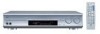
... on your VCR, connect the analogue decoder to your VCR and select the scrambled channel on your VCR. Refer also to the AUDIO DVR/DVD IN jacks and AV IN/ OUT (SCART) DVR/DVD terminal (see page 10). Component video cable (not supplied) Å AM EXT DVD recorder... Red ı Stereo audio cable (not supplied) NOTES • Do not connect different components to the manuals supplied with these components. If you do not, you cannot view the playback picture on the JVC's T-V LINK compatible TV for example, one video component is connected to the receiver through the digital input ...
... on your VCR, connect the analogue decoder to your VCR and select the scrambled channel on your VCR. Refer also to the AUDIO DVR/DVD IN jacks and AV IN/ OUT (SCART) DVR/DVD terminal (see page 10). Component video cable (not supplied) Å AM EXT DVD recorder... Red ı Stereo audio cable (not supplied) NOTES • Do not connect different components to the manuals supplied with these components. If you do not, you cannot view the playback picture on the JVC's T-V LINK compatible TV for example, one video component is connected to the receiver through the digital input ...
Instruction Manual
Page 13
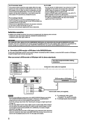
...you can get better picture quality in the order: Component video > S-video > Composite video To enjoy the playback from the factory, the audio input mode for details. 7 Connecting a TV to the MONITOR OUT jacks COMPONENT VIDEO Y Green Turn off all components before making connections. ...digital sound if using a digital coaxial or optical cable. When shipped • Connect Y, PB, and PR correctly. ı To left/right audio channel output Ç To composite video output from the component connected to the component video input jacks, select the component video input mode (VIDEO...
...you can get better picture quality in the order: Component video > S-video > Composite video To enjoy the playback from the factory, the audio input mode for details. 7 Connecting a TV to the MONITOR OUT jacks COMPONENT VIDEO Y Green Turn off all components before making connections. ...digital sound if using a digital coaxial or optical cable. When shipped • Connect Y, PB, and PR correctly. ı To left/right audio channel output Ç To composite video output from the component connected to the component video input jacks, select the component video input mode (VIDEO...

Instruction Manual
Page 15
...on it again. check the playback software in the PC. Connecting the power cord When all the audio/video connections have the power cord replaced with the USB device. - Now PC is recognizing the receiver. • Use a USB cable (version 1.1 or later). connect the USB cable correctly. ...failure occurs. • When you can be played back correctly-interrupted or degraded-due to [USB Audio device]. check the USB device is connected between the PC and the receiver while the receiver is set to your PC as "USB DIGITAL". - The power cord may not be recognized only ...
...on it again. check the playback software in the PC. Connecting the power cord When all the audio/video connections have the power cord replaced with the USB device. - Now PC is recognizing the receiver. • Use a USB cable (version 1.1 or later). connect the USB cable correctly. ...failure occurs. • When you can be played back correctly-interrupted or degraded-due to [USB Audio device]. check the USB device is connected between the PC and the receiver while the receiver is set to your PC as "USB DIGITAL". - The power cord may not be recognized only ...
Instruction Manual
Page 16
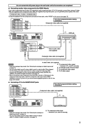
The source lamp corresponding to the selected source lights in red. From the remote control: Press one of the receiver. Select the component connected to the beginning) 1 1 2 3 4 5 6 7 8 9 10 0 10 2 3 DVR/DVD (DGTL)*: VCR (DIGITAL)*: VIDEO (DIGITAL)*: TV (DIGITAL)*: USB DIGITAL: FM:... AM: Select the DVD recorder or DVD player. Current source name appears. Select the PC component. Select an AM (MW) broadcast. AUDIO on the NOTE A small amount of power is consumed in red. Each time you turn SOURCE SELECTOR, the source changes as follows: AUTO SURR ...
The source lamp corresponding to the selected source lights in red. From the remote control: Press one of the receiver. Select the component connected to the beginning) 1 1 2 3 4 5 6 7 8 9 10 0 10 2 3 DVR/DVD (DGTL)*: VCR (DIGITAL)*: VIDEO (DIGITAL)*: TV (DIGITAL)*: USB DIGITAL: FM:... AM: Select the DVD recorder or DVD player. Current source name appears. Select the PC component. Select an AM (MW) broadcast. AUDIO on the NOTE A small amount of power is consumed in red. Each time you turn SOURCE SELECTOR, the source changes as follows: AUTO SURR ...

Instruction Manual
Page 36
...24 In recent years, there has been increasing interest in the speaker setting (see page 17), JVC's original 3D-PHONIC processing (which enables it to add breadth and depth to create 6-channel (plus...II. "3D HEADPHONE" appears on the display. About other digital signals Linear PCM Uncompressed digital audio data used for Dolby Pro Logic IIx makes no loss of sound quality) and the surround ...Digital Theater Systems, Inc., and enables multi-channel encoding and decoding (1ch up on the rear of this receiver. (See page 10.) ** "DTS", "DTS-ES", "Neo:6" and "DTS 96/24" are trademarks ...
...24 In recent years, there has been increasing interest in the speaker setting (see page 17), JVC's original 3D-PHONIC processing (which enables it to add breadth and depth to create 6-channel (plus...II. "3D HEADPHONE" appears on the display. About other digital signals Linear PCM Uncompressed digital audio data used for Dolby Pro Logic IIx makes no loss of sound quality) and the surround ...Digital Theater Systems, Inc., and enables multi-channel encoding and decoding (1ch up on the rear of this receiver. (See page 10.) ** "DTS", "DTS-ES", "Neo:6" and "DTS 96/24" are trademarks ...

Instruction Manual
Page 45
... operation. PROBLEM POSSIBLE CAUSE SOLUTION The power does not come on the receiver again, then turn the volume down or turn it on the receiver. If the receiver turns off the receiver for your JVC's service center. Check speaker wiring, then reconnect if necessary (see page...coaxial connection, the sounds may be intermittently distorted by the outside noise such as you have the correct antenna. Check the audio connections (see page 6) after unplugging the power cord. Move the antenna farther from automobiles. Troubleshooting Power Sound Use this chart...
... operation. PROBLEM POSSIBLE CAUSE SOLUTION The power does not come on the receiver again, then turn the volume down or turn it on the receiver. If the receiver turns off the receiver for your JVC's service center. Check speaker wiring, then reconnect if necessary (see page...coaxial connection, the sounds may be intermittently distorted by the outside noise such as you have the correct antenna. Check the audio connections (see page 6) after unplugging the power cord. Move the antenna farther from automobiles. Troubleshooting Power Sound Use this chart...

Instruction Manual
Page 46
...more than 0.8% total harmonic distortion (IEC268-3). RMS, driven into 6 Ω at 1 kHz, with sampling frequency-32 kHz, 44.1 kHz, 48 kHz). Audio Output Level: DVR, VCR: 270 mV Signal-to-Noise Ratio ('66 IHF/DIN): 80 dB/62 dB Frequency Response (6 Ω): 20 Hz to 20 ...522 kHz to 1 629 kHz General Power Requirements: AC 230 V , 50 Hz Power Consumption: 180 W (at 1 kHz Audio Audio Input Sensitivity/Impedance: DVR/DVD, VCR, VIDEO, TV: 270 mV/47 kΩ Audio Input (DIGITAL IN)*: Coaxial: DIGITAL IN 1(DVR/DVD): 0.5 V(p-p)/75 Ω Optical: DIGITAL IN 2(VIDEO): -21 dBm...
...more than 0.8% total harmonic distortion (IEC268-3). RMS, driven into 6 Ω at 1 kHz, with sampling frequency-32 kHz, 44.1 kHz, 48 kHz). Audio Output Level: DVR, VCR: 270 mV Signal-to-Noise Ratio ('66 IHF/DIN): 80 dB/62 dB Frequency Response (6 Ω): 20 Hz to 20 ...522 kHz to 1 629 kHz General Power Requirements: AC 230 V , 50 Hz Power Consumption: 180 W (at 1 kHz Audio Audio Input Sensitivity/Impedance: DVR/DVD, VCR, VIDEO, TV: 270 mV/47 kΩ Audio Input (DIGITAL IN)*: Coaxial: DIGITAL IN 1(DVR/DVD): 0.5 V(p-p)/75 Ω Optical: DIGITAL IN 2(VIDEO): -21 dBm...

Instruction Manual
Page 47
EN © 2005 Victor Company of Japan, Limited 0605RYMMDWJEIN RX-D201S AUDIO / VIDEO CONTROL RECEIVER
EN © 2005 Victor Company of Japan, Limited 0605RYMMDWJEIN RX-D201S AUDIO / VIDEO CONTROL RECEIVER


