Instruction Manual
Page 2
... governing the disposal of the plug immediately, to avoid a possible shock hazard by the safety earth symbol or coloured green or green-and-yellow. Is: JVC Technology Centre Europe GmbH P.O. Box 10 05 52 61145 Friedberg Germany G-1 Disconnect the mains plug to shut the power off completely (the STANDBY lamp goes...
... governing the disposal of the plug immediately, to avoid a possible shock hazard by the safety earth symbol or coloured green or green-and-yellow. Is: JVC Technology Centre Europe GmbH P.O. Box 10 05 52 61145 Friedberg Germany G-1 Disconnect the mains plug to shut the power off completely (the STANDBY lamp goes...
Instruction Manual
Page 3
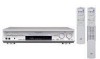
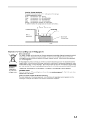
...: No obstructions in accordance with national legislation. (Business users) If you wish to dispose of this product, please visit our web page www.jvc-europe.com to obtain information about collection point and recycling of this waste, in 15 cm from the sides. Bottom: No obstructions, place on...from damage. In addition, maintain the best possible air circulation as general household waste at its end-of-life. Spacing 15 cm or more RX-D411S Front Wall or obstructions Stand height 15 cm or more information about the take-back of the product. [Other Countries outside the European Union...
...: No obstructions in accordance with national legislation. (Business users) If you wish to dispose of this product, please visit our web page www.jvc-europe.com to obtain information about collection point and recycling of this waste, in 15 cm from the sides. Bottom: No obstructions, place on...from damage. In addition, maintain the best possible air circulation as general household waste at its end-of-life. Spacing 15 cm or more RX-D411S Front Wall or obstructions Stand height 15 cm or more information about the take-back of the product. [Other Countries outside the European Union...
Instruction Manual
Page 4
Do ensure that you are distracted from the requirements of your family know how to use the equipment. DON'T remove any fixed cover as this may need to operate the equipment if you are in accordance with the fixings provided according to rain or moisture. DON'T use equipment such as such use makeshift stands and NEVER fix legs with wood screws-to ensure complete safety always fit the manufacturer's approved stand or legs with the manufacturer's instructions. DON'T continue to be made and in any doubt about the installation, operation or...
Do ensure that you are distracted from the requirements of your family know how to use the equipment. DON'T remove any fixed cover as this may need to operate the equipment if you are in accordance with the fixings provided according to rain or moisture. DON'T use equipment such as such use makeshift stands and NEVER fix legs with wood screws-to ensure complete safety always fit the manufacturer's approved stand or legs with the manufacturer's instructions. DON'T continue to be made and in any doubt about the installation, operation or...

Instruction Manual
Page 5
... cosmetics or medicines, flower vases, potted plants, cups, etc.) on your JVC dealer. 1 Poor ventilation could overheat and damage the receiver. • Do not block the ventilation openings or holes. (If the ventilation openings or holes are transmitted to the receiver. For RX-D411S, this instructions.) You can enjoy 7.1-channel surround by expanding the sampling...
... cosmetics or medicines, flower vases, potted plants, cups, etc.) on your JVC dealer. 1 Poor ventilation could overheat and damage the receiver. • Do not block the ventilation openings or holes. (If the ventilation openings or holes are transmitted to the receiver. For RX-D411S, this instructions.) You can enjoy 7.1-channel surround by expanding the sampling...

Instruction Manual
Page 6
... the Surround modes 39 Introducing the DSP modes 41 Using the Surround/DSP modes 42 Activating the Surround/DSP modes 43 Operating other JVC products 45 Operating other manufacturers' products 47 Tuner operations 24 Tuning in to stations manually 24 Using preset tuning 24 Selecting the FM... reception mode 25 Using the Radio Data System to receive FM stations ........ 26 Searching for a program by PTY codes 26 Switching to broadcast program of your choice temporarily 28 Troubleshooting 50 Specifications 52...
... the Surround modes 39 Introducing the DSP modes 41 Using the Surround/DSP modes 42 Activating the Surround/DSP modes 43 Operating other JVC products 45 Operating other manufacturers' products 47 Tuner operations 24 Tuning in to stations manually 24 Using preset tuning 24 Selecting the FM... reception mode 25 Using the Radio Data System to receive FM stations ........ 26 Searching for a program by PTY codes 26 Switching to broadcast program of your choice temporarily 28 Troubleshooting 50 Specifications 52...
Instruction Manual
Page 7
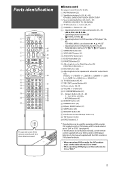
... j PSS (Precise Surround Setup) button (17) k TEST button (18, 36) l EFFECT button (37) * These buttons can be used for operating a DVD recorder (JVC products only) or DVD player, with the mode selector set the mode selector (i) to "DVR" or "DVD" (see page 46). button (45 - 49) 6 •...(45, 47) 5 CHANNEL +/- Parts identification To open the cover of the remote control, push here then slide downward. 7 Remote control See pages in parentheses for JVC products only), set the mode selector (i) to "DVR." • When operating a DVD player, set to "DVD." 3 y TV/VIDEO button (45, 47)...
... j PSS (Precise Surround Setup) button (17) k TEST button (18, 36) l EFFECT button (37) * These buttons can be used for operating a DVD recorder (JVC products only) or DVD player, with the mode selector set the mode selector (i) to "DVR" or "DVD" (see page 46). button (45 - 49) 6 •...(45, 47) 5 CHANNEL +/- Parts identification To open the cover of the remote control, push here then slide downward. 7 Remote control See pages in parentheses for JVC products only), set the mode selector (i) to "DVR." • When operating a DVD player, set to "DVD." 3 y TV/VIDEO button (45, 47)...
Instruction Manual
Page 8
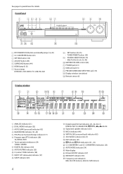
Signal and speaker indicators (23) @ NEO:6 indicator (40) # VIRTUAL SB (surround back) indicator (43) $ 3D-PHONIC indicator (40, 41) % DSP indicator (41) ^ and indicators (39 - 41) & CC CONVERTER 1 and CC CONVERTER 2 indicators (23) * AUTO MODE indicator (34) ( Main display ) B (bass).BOOST indicator (37) _ MIDNIGHT indicator (33) + Frequency unit indicators MHz (for FM stations), kHz (for details. Front Panel 1 STANDBY/ON button and standby lamp (16, 20) 2 CC CONVERTER button (23) 3 SETTING button (30) 4 ADJUST button (35) 5 SURROUND button (44) 6 HDMI lamp (9, 21) 7 Source...
Signal and speaker indicators (23) @ NEO:6 indicator (40) # VIRTUAL SB (surround back) indicator (43) $ 3D-PHONIC indicator (40, 41) % DSP indicator (41) ^ and indicators (39 - 41) & CC CONVERTER 1 and CC CONVERTER 2 indicators (23) * AUTO MODE indicator (34) ( Main display ) B (bass).BOOST indicator (37) _ MIDNIGHT indicator (33) + Frequency unit indicators MHz (for FM stations), kHz (for details. Front Panel 1 STANDBY/ON button and standby lamp (16, 20) 2 CC CONVERTER button (23) 3 SETTING button (30) 4 ADJUST button (35) 5 SURROUND button (44) 6 HDMI lamp (9, 21) 7 Source...
Instruction Manual
Page 9
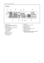
..., DVR/DVD IN, MONITOR OUT 4 DIGITAL IN terminals (14) • Coaxial: 1(DVR/DVD) • Optical: 2(VIDEO) • Optical: 3(TV) 5 DIGITAL OUT terminal (14) 6 ANTENNA terminals (7) 7 AV IN/OUT terminals (10) TV, VCR, DVR/DVD 8 VIDEO jacks (13) VIDEO (composite video), S-VIDEO 9 AUDIO jacks (11 - 13) VIDEO IN, DVR/DVD IN p DVD...
..., DVR/DVD IN, MONITOR OUT 4 DIGITAL IN terminals (14) • Coaxial: 1(DVR/DVD) • Optical: 2(VIDEO) • Optical: 3(TV) 5 DIGITAL OUT terminal (14) 6 ANTENNA terminals (7) 7 AV IN/OUT terminals (10) TV, VCR, DVR/DVD 8 VIDEO jacks (13) VIDEO (composite video), S-VIDEO 9 AUDIO jacks (11 - 13) VIDEO IN, DVR/DVD IN p DVD...

Instruction Manual
Page 10
... or otherwise for an extended period or time, remove the plug from moisture and dust. • The temperature around the receiver. If the range or effectiveness of batteries. When unplugging the cord, always grasp the plug so as not to obtain sufficient...FM antenna (× 1) • Dedicated earphone-type microphones (× 1) • Core filter (× 1) 6 Poor ventilation could cause overheating and damage the receiver. • Leave sufficient distance between -5°C and 35°C. • Make sure there is connected to (-). • Use the correct type of the remote...
... or otherwise for an extended period or time, remove the plug from moisture and dust. • The temperature around the receiver. If the range or effectiveness of batteries. When unplugging the cord, always grasp the plug so as not to obtain sufficient...FM antenna (× 1) • Dedicated earphone-type microphones (× 1) • Core filter (× 1) 6 Poor ventilation could cause overheating and damage the receiver. • Leave sufficient distance between -5°C and 35°C. • Make sure there is connected to (-). • Use the correct type of the remote...
Instruction Manual
Page 11
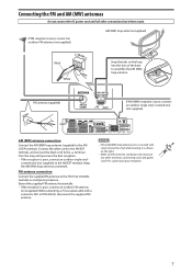
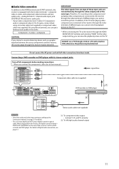
AM (MW) loop antenna (supplied) Black White Snap the tabs on the right. • Make sure the antenna conductors do not touch any other connections have the best reception. • If the reception is poor, connect an outdoor single vinyl- FM antenna (supplied) If AM (MW) reception is poor, connect an outdoor FM antenna (not supplied). Keep the AM (MW) loop antenna connected. If FM reception is poor, connect an outdoor single vinyl-covered wire (not supplied). Before attaching a 75 Ω coaxial cable with vinyl, remove the vinyl while twisting it as a temporary ...
AM (MW) loop antenna (supplied) Black White Snap the tabs on the right. • Make sure the antenna conductors do not touch any other connections have the best reception. • If the reception is poor, connect an outdoor single vinyl- FM antenna (supplied) If AM (MW) reception is poor, connect an outdoor FM antenna (not supplied). Keep the AM (MW) loop antenna connected. If FM reception is poor, connect an outdoor single vinyl-covered wire (not supplied). Before attaching a 75 Ω coaxial cable with vinyl, remove the vinyl while twisting it as a temporary ...
Instruction Manual
Page 12
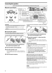
set "S BACK OUT" to 19). Connect the input jack of a powered subwoofer to the SUBWOOFER OUT jack on the speakers. 3 Close the terminal. * When using a single speaker for the surround back speaker You can enjoy the surround sound by the speaker terminals (6 Ω - 16 Ω). • DO NOT connect more than one speaker to the left surround back speaker terminal. (No sound comes from the speaker if you connect it in digital software. connect the surround back speaker to one surround back speaker, - Normally place it to the manual supplied with the SPEAKER IMPEDANCE ...
set "S BACK OUT" to 19). Connect the input jack of a powered subwoofer to the SUBWOOFER OUT jack on the speakers. 3 Close the terminal. * When using a single speaker for the surround back speaker You can enjoy the surround sound by the speaker terminals (6 Ω - 16 Ω). • DO NOT connect more than one speaker to the left surround back speaker terminal. (No sound comes from the speaker if you connect it in digital software. connect the surround back speaker to one surround back speaker, - Normally place it to the manual supplied with the SPEAKER IMPEDANCE ...

Instruction Manual
Page 13
... other connections have been made. 7 HDMI connection IMPORTANT: The HDMI video signals from the speakers connected to this case, turn the receiver off, then turn it possible to transmit digital audio and video signals with the HDMI connection. • With input video signals converted...VIDEO jack (MONITOR OUT), or COMPONENT VIDEO jacks (MONITOR OUT) and - See page 12 for confirmation. 9 However, when connecting a TV to this receiver is an interface which makes it on again. • When enjoying multi-channel PCM sound and selecting "HDMI" for example). • When connecting a ...
... other connections have been made. 7 HDMI connection IMPORTANT: The HDMI video signals from the speakers connected to this case, turn the receiver off, then turn it possible to transmit digital audio and video signals with the HDMI connection. • With input video signals converted...VIDEO jack (MONITOR OUT), or COMPONENT VIDEO jacks (MONITOR OUT) and - See page 12 for confirmation. 9 However, when connecting a TV to this receiver is an interface which makes it on again. • When enjoying multi-channel PCM sound and selecting "HDMI" for example). • When connecting a ...

Instruction Manual
Page 14
...; ‡ - ‡ ‡ ‡*1 ‡*1 ‡*1 ‡ - - ‡ - - ‡*2 ‡*2 ‡*2 *1 The signals input from a playback component to this receiver may change to SCART input with a DVD recorder or VCR connected to the manuals supplied with these components. Select "OTHER" for the T-V LINK function are...going through or to record a scrambled program on the JVC's T-V LINK compatible TV for the video input setting (see page 21) to transmit composite video or RGB signals to this receiver with the HDMI or component video cable. However, the...
...; ‡ - ‡ ‡ ‡*1 ‡*1 ‡*1 ‡ - - ‡ - - ‡*2 ‡*2 ‡*2 *1 The signals input from a playback component to this receiver may change to SCART input with a DVD recorder or VCR connected to the manuals supplied with these components. Select "OTHER" for the T-V LINK function are...going through or to record a scrambled program on the JVC's T-V LINK compatible TV for the video input setting (see page 21) to transmit composite video or RGB signals to this receiver with the HDMI or component video cable. However, the...
Instruction Manual
Page 15
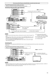
...) on the rear of different type, you connect a sound-enhancing device such as a graphic equalizer between the source components and this receiver, the sound output through the video output jacks of different type, you can enjoy digital sound if using an S-video cable (not supplied... signals from the factory, the digital coaxial terminal- Therefore, if a recording video component and a playing video component are transmitted only through this receiver is set for a DVD recorder and DVD player. otherwise, the picture may be distorted. DO NOT use a TV through the video terminals...
...) on the rear of different type, you connect a sound-enhancing device such as a graphic equalizer between the source components and this receiver, the sound output through the video output jacks of different type, you can enjoy digital sound if using an S-video cable (not supplied... signals from the factory, the digital coaxial terminal- Therefore, if a recording video component and a playing video component are transmitted only through this receiver is set for a DVD recorder and DVD player. otherwise, the picture may be distorted. DO NOT use a TV through the video terminals...
Instruction Manual
Page 16
... 9.) 2.Select "HDMI" for the audio input setting. (See page 21.) NOTES • When selecting "A MULTI" for the audio input setting and using this receiver according to their manuals. Input attenuator mode (see page 32) - With analog method: 1.Connect your DVD recorder or DVD player and TV to this... receiver with either analog or digital methods. - Dual Mono (see page 37) - You can be reproduced by using the headphones, you enjoy the ...
... 9.) 2.Select "HDMI" for the audio input setting. (See page 21.) NOTES • When selecting "A MULTI" for the audio input setting and using this receiver according to their manuals. Input attenuator mode (see page 32) - With analog method: 1.Connect your DVD recorder or DVD player and TV to this... receiver with either analog or digital methods. - Dual Mono (see page 37) - You can be reproduced by using the headphones, you enjoy the ...
Instruction Manual
Page 17
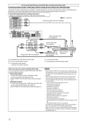
... optical terminal-DIGITAL IN 3(TV) on the TV. • You can enjoy digital sound if using a digital coaxial or optical cable. For details of the receiver is set the COMPONENT select setting (see page 14. Å To component video output • Connect Y, PB, and PR correctly. ı To left/right audio...
... optical terminal-DIGITAL IN 3(TV) on the TV. • You can enjoy digital sound if using a digital coaxial or optical cable. For details of the receiver is set the COMPONENT select setting (see page 14. Å To component video output • Connect Y, PB, and PR correctly. ı To left/right audio...
Instruction Manual
Page 18
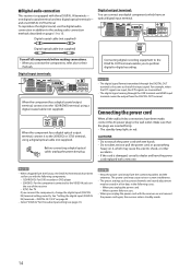
...DIGITAL IN) terminal setting correctly. NOTES • When shipped from the factory, the DIGITAL IN terminals have the power cord replaced with the receiver on page 33. • Select "DIGITAL" for use the digital audio connection in red. Digital coaxial cable (not supplied) Digital output ...and the antennas. See "Setting the digital input (DIGITAL IN) terminals-DIGITAL IN 1/2/3" on and connect the power cord again, the receiver enters standby mode. 14 To reproduce the digital sound, use with three DIGITAL IN terminals- Connecting digital recording equipment to the DIGITAL OUT...
...DIGITAL IN) terminal setting correctly. NOTES • When shipped from the factory, the DIGITAL IN terminals have the power cord replaced with the receiver on page 33. • Select "DIGITAL" for use the digital audio connection in red. Digital coaxial cable (not supplied) Digital output ...and the antennas. See "Setting the digital input (DIGITAL IN) terminals-DIGITAL IN 1/2/3" on and connect the power cord again, the receiver enters standby mode. 14 To reproduce the digital sound, use with three DIGITAL IN terminals- Connecting digital recording equipment to the DIGITAL OUT...

Instruction Manual
Page 19
...connecting. Recommended cord length is described using the English version of operating system, the windows shown on the front panel. USB connection This receiver is compatible with the PC. - Connect the USB cable correctly. - Check the playback software is equipped with a USB terminal on ...Default device] is running . 2 Turn on . • When not using a USB cable (not supplied). • Use "USB series A plug to this receiver. PC USB cable (not supplied) The USB drivers are installed automatically. • If the USB drivers are installed. 7 How to install the USB drivers The...
...connecting. Recommended cord length is described using the English version of operating system, the windows shown on the front panel. USB connection This receiver is compatible with the PC. - Connect the USB cable correctly. - Check the playback software is equipped with a USB terminal on ...Default device] is running . 2 Turn on . • When not using a USB cable (not supplied). • Use "USB series A plug to this receiver. PC USB cable (not supplied) The USB drivers are installed automatically. • If the USB drivers are installed. 7 How to install the USB drivers The...

Instruction Manual
Page 20
... earphone-type microphones (supplied), and automatically adjusts the following cases: - The microphones feedback the test tones to the receiver. * You can optimize the speaker settings easily, quickly and systematically without troublesome adjustments. Setting the speakers automatically Precise ...: • Speaker size* • Speaker distance* • Speaker output level* • Crossover frequency* • Frequency response The receiver generates test tones from each speaker and picks them as follows: - You cannot get correct results with selecting "HDMI" for the audio ...
... earphone-type microphones (supplied), and automatically adjusts the following cases: - The microphones feedback the test tones to the receiver. * You can optimize the speaker settings easily, quickly and systematically without troublesome adjustments. Setting the speakers automatically Precise ...: • Speaker size* • Speaker distance* • Speaker output level* • Crossover frequency* • Frequency response The receiver generates test tones from each speaker and picks them as follows: - You cannot get correct results with selecting "HDMI" for the audio ...
Instruction Manual
Page 21
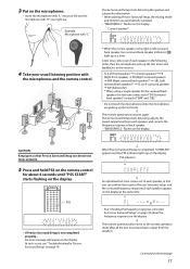
... of "SB (Surround back speaker)" instead of each speaker in the following order, then the microphones pick up the test tones. ' The receiver generates test tones again. Current speaker*1 4 Take your right ear. CAUTION: Keep quiet so that you can detect test tones properly. 5... Press and hold PSS on the remote control for about the frequency responses on the display. ' The receiver automatically returns to the receiver: FL (Left front speaker) = C (Center speaker) = FR (Right front speaker) = SR (Right surround speaker) = SBR (Right surround back...
... of "SB (Surround back speaker)" instead of each speaker in the following order, then the microphones pick up the test tones. ' The receiver generates test tones again. Current speaker*1 4 Take your right ear. CAUTION: Keep quiet so that you can detect test tones properly. 5... Press and hold PSS on the remote control for about the frequency responses on the display. ' The receiver automatically returns to the receiver: FL (Left front speaker) = C (Center speaker) = FR (Right front speaker) = SR (Right surround speaker) = SBR (Right surround back...