
Instructions
Page 4
... the powered subwoofer 13 Connecting to an analog component 13 Connecting to a digital component 13 Connecting a USB mass storage class device 13 Connecting the power cord 13 Operating external components with the remote control 14 Operating the TV 14 Operating the DBS tuner or CATV converter 15 Operating the VCR 15...
... the powered subwoofer 13 Connecting to an analog component 13 Connecting to a digital component 13 Connecting a USB mass storage class device 13 Connecting the power cord 13 Operating external components with the remote control 14 Operating the TV 14 Operating the DBS tuner or CATV converter 15 Operating the VCR 15...

Instructions
Page 5
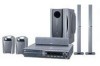
.... • Remote control (1) • Batteries (2) • FM antenna (1) • AM loop antenna (1) • Power cord (1) • System cord (1) • Composite video cord (1) • Speaker cords (for TH-C60/TH-C50) 4 m: For satellite (front left/right) and center speakers (3) 10 m: For satellite speakers (surround left/right) (2)... • Screws TH-C60: M5 x 40 mm (4) M4 x 20 mm (8) TH-C50: M5 x 40 mm (2) M4 x 20 mm (4) • Speaker cord clamps TH-C60 (4) TH-C50 (2) 2 The number in parentheses is connected to vibration. Do not...
.... • Remote control (1) • Batteries (2) • FM antenna (1) • AM loop antenna (1) • Power cord (1) • System cord (1) • Composite video cord (1) • Speaker cords (for TH-C60/TH-C50) 4 m: For satellite (front left/right) and center speakers (3) 10 m: For satellite speakers (surround left/right) (2)... • Screws TH-C60: M5 x 40 mm (4) M4 x 20 mm (8) TH-C50: M5 x 40 mm (2) M4 x 20 mm (4) • Speaker cord clamps TH-C60 (4) TH-C50 (2) 2 The number in parentheses is connected to vibration. Do not...

Instructions
Page 9
Description of parts and controls Powered subwoofer SP-PWC60/SP-PWC50 SP-PWC40 13 POWER ON 11 lamp: 16 Front Power cord: 13 Rear 13 11 POWER ON lamp: 16 Front NOTE • For safety reasons, always ensure that there is sufficient space behind the powered subwoofer. * Do not block the ventilation openings to allow proper air circulation by the cooling fan. Power cord: 13 Rear 6
Description of parts and controls Powered subwoofer SP-PWC60/SP-PWC50 SP-PWC40 13 POWER ON 11 lamp: 16 Front Power cord: 13 Rear 13 11 POWER ON lamp: 16 Front NOTE • For safety reasons, always ensure that there is sufficient space behind the powered subwoofer. * Do not block the ventilation openings to allow proper air circulation by the cooling fan. Power cord: 13 Rear 6
Instructions
Page 11
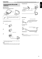
...AM loop antenna Center unit Outdoor single vinyl-covered wire antenna (not supplied) If the antenna cord is well-shielded against interference. • Turn the loop antenna until all other terminals, connecting cords or power cords. If reception is poor Center unit Outdoor FM antenna (not supplied) Standard type (75 &#...8486; coaxial) connector Outdoor FM antenna cord (not supplied) NOTE • We recommend that you have been made. NOTE • Make sure the antenna conductors do not touch any...
...AM loop antenna Center unit Outdoor single vinyl-covered wire antenna (not supplied) If the antenna cord is well-shielded against interference. • Turn the loop antenna until all other terminals, connecting cords or power cords. If reception is poor Center unit Outdoor FM antenna (not supplied) Standard type (75 &#...8486; coaxial) connector Outdoor FM antenna cord (not supplied) NOTE • We recommend that you have been made. NOTE • Make sure the antenna conductors do not touch any...

Instructions
Page 12
... White Black Black You can route the speaker cord by using speaker cord clamp (supplied). 9 Without stand: Refer to drop any component part while assembling; Stand (or speaker directly)* Screw M4 x 20 mm (supplied)* * When assembling the speaker with the base plate. TH-C60/TH-C50 7 For TH-C60: Assemble front speakers and surround speakers...
... White Black Black You can route the speaker cord by using speaker cord clamp (supplied). 9 Without stand: Refer to drop any component part while assembling; Stand (or speaker directly)* Screw M4 x 20 mm (supplied)* * When assembling the speaker with the base plate. TH-C60/TH-C50 7 For TH-C60: Assemble front speakers and surround speakers...

Instructions
Page 13
...bottom) 2 Red White Black Black Center speaker (SP-THC60C) (1) Red White Black Black For TH-C40, the front, surround and center speakers are equipped with their speaker cords attached directly to their speaker unit instead of having speaker terminals on their cabinet. Connections Do not... connect the power cord until all other connections have been made. 7 Connecting the surround speakers - TH-C50 7 Connecting the center ...
...bottom) 2 Red White Black Black Center speaker (SP-THC60C) (1) Red White Black Black For TH-C40, the front, surround and center speakers are equipped with their speaker cords attached directly to their speaker unit instead of having speaker terminals on their cabinet. Connections Do not... connect the power cord until all other connections have been made. 7 Connecting the surround speakers - TH-C50 7 Connecting the center ...

Instructions
Page 14
...falling off and remove. otherwise, the speakers may fall down or break, possibly causing an injury. Connections Do not connect the power cord until all other than one speaker terminal. • When installing the satellite speakers on the rear of the same speaker impedance (SPEAKER...do not pull the speaker cords; Powered subwoofer TH-C60: SP-PWC60 TH-C50: SP-PWC50 TH-C40: SP-PWC40 Front speakers TH-C60: SP-THC60F TH-C50: SP-THC60F TH-C40: SP-THC40F Speaker cord • Connect the black cords to the black (r) terminals. • Connect the white cords to the (q) terminals ...
...falling off and remove. otherwise, the speakers may fall down or break, possibly causing an injury. Connections Do not connect the power cord until all other than one speaker terminal. • When installing the satellite speakers on the rear of the same speaker impedance (SPEAKER...do not pull the speaker cords; Powered subwoofer TH-C60: SP-PWC60 TH-C50: SP-PWC50 TH-C40: SP-PWC40 Front speakers TH-C60: SP-THC60F TH-C50: SP-THC60F TH-C40: SP-THC40F Speaker cord • Connect the black cords to the black (r) terminals. • Connect the white cords to the (q) terminals ...

Instructions
Page 15
... a high quality picture by setting the progressive scan mode to active. (See page 18.) TV To component video input Center unit Component video cord (not supplied) NOTE • While playing back DivX/ASF files, this happens, move the speakers away from HDMI MONITOR OUT terminal, see ... HDMI (High Definition Multimedia Interface) is HDMI? So, pay attention to a TV with the composite or S-video jacks Center unit Composite video cord (supplied) or S-video cord (not supplied) Align the 5 marks. By connecting this , do not place the speakers nearby the TV or monitor. • Be sure...
... a high quality picture by setting the progressive scan mode to active. (See page 18.) TV To component video input Center unit Component video cord (not supplied) NOTE • While playing back DivX/ASF files, this happens, move the speakers away from HDMI MONITOR OUT terminal, see ... HDMI (High Definition Multimedia Interface) is HDMI? So, pay attention to a TV with the composite or S-video jacks Center unit Composite video cord (supplied) or S-video cord (not supplied) Align the 5 marks. By connecting this , do not place the speakers nearby the TV or monitor. • Be sure...

Instructions
Page 16
... USB hub. • You cannot charge the USB mass storage class device while connecting it to damage the cord. 13 It may not play . (See page 17.) When connecting a video component such as the source,... recorder (3) 1 To composite video output 2 To S-video output 3 To audio output NOTE • The signals input to unplug the cord. Do not use a cable less than 1 m in length. • This system is compatible with the USB 2.0 Full-Speed (...a malfunction of both the system and the device. • JVC bears no responsibility for any loss of files in a USB mass storage class device, do not disconnect ...
... USB hub. • You cannot charge the USB mass storage class device while connecting it to damage the cord. 13 It may not play . (See page 17.) When connecting a video component such as the source,... recorder (3) 1 To composite video output 2 To S-video output 3 To audio output NOTE • The signals input to unplug the cord. Do not use a cable less than 1 m in length. • This system is compatible with the USB 2.0 Full-Speed (...a malfunction of both the system and the device. • JVC bears no responsibility for any loss of files in a USB mass storage class device, do not disconnect ...

Instructions
Page 19
Turning the system on the center unit - Unplug the power cord from the speakers on TV even though "HDMI AUDIO OUT" in the AUDIO menu (see page 34) is linked to the center unit. One of ...
Turning the system on the center unit - Unplug the power cord from the speakers on TV even though "HDMI AUDIO OUT" in the AUDIO menu (see page 34) is linked to the center unit. One of ...

Instructions
Page 21
...- 480i/1080i indicates 480/1080 scanning lines with interlaced format. - 480p/720p indicates 480/720 scanning lines with the S-video or the composite video cord. • Although the picture may be accommodated to the beginning) (Unit: min.) Example: minutes To check the remaining time Press SLEEP once. ... to +6. to adjust the level from -6 to +10 (in 2 steps). To change the scan mode to the interlace mode. • All JVC progressive TVs and High-Definition TVs are some progressive TVs and High-Definition TVs that the center unit is connected to show the target speaker...
...- 480i/1080i indicates 480/1080 scanning lines with interlaced format. - 480p/720p indicates 480/720 scanning lines with the S-video or the composite video cord. • Although the picture may be accommodated to the beginning) (Unit: min.) Example: minutes To check the remaining time Press SLEEP once. ... to +6. to adjust the level from -6 to +10 (in 2 steps). To change the scan mode to the interlace mode. • All JVC progressive TVs and High-Definition TVs are some progressive TVs and High-Definition TVs that the center unit is connected to show the target speaker...

Instructions
Page 41
... TV for "MON." (Monitor Out) setting (see pages 12 and 13. 2 Connect the center unit to the appropriate position so that you to operate JVC's video components via the video components terminals. When you turn off the system, the TV and VCR will continue recording. • When starting playback on... select DVD or VCR as follows. • Refer also to the manuals supplied with its safety tab into the AC outlets, unplug their AC power cords first. 1 Connect the center unit to a TV and VCR. • For details, see page 32), the system automatically turns on and changes the input ...
... TV for "MON." (Monitor Out) setting (see pages 12 and 13. 2 Connect the center unit to the appropriate position so that you to operate JVC's video components via the video components terminals. When you turn off the system, the TV and VCR will continue recording. • When starting playback on... select DVD or VCR as follows. • Refer also to the manuals supplied with its safety tab into the AC outlets, unplug their AC power cords first. 1 Connect the center unit to a TV and VCR. • For details, see page 32), the system automatically turns on and changes the input ...

Instructions
Page 42
... TV. (See page 12.) Disconnect the HDMI cable and connect it is compatible with this system and/or TV. Connect the power cord and system cord correctly. (See page 13.) The remote control does The batteries are distorted. Replace the batteries. (See page 7.) Hide the remote ... the system • Stains on . 39 Check the connection. Select the correct source. (See page 17.) No picture is displayed The video cord is not playable. on the remote sensor. References Maintenance 7 Handling Discs • Remove the disc from its case by referring to "Maintenance" above...
... TV. (See page 12.) Disconnect the HDMI cable and connect it is compatible with this system and/or TV. Connect the power cord and system cord correctly. (See page 13.) The remote control does The batteries are distorted. Replace the batteries. (See page 7.) Hide the remote ... the system • Stains on . 39 Check the connection. Select the correct source. (See page 17.) No picture is displayed The video cord is not playable. on the remote sensor. References Maintenance 7 Handling Discs • Remove the disc from its case by referring to "Maintenance" above...


