
Dimension Guide
Page 1
... cabinet supplier to convert the range cooktop from the gas specified on the model/serial number rating plate. 30", 36", and 48" Professional Dual Fuel Convection Ranges PRODUCT MODEL NUMBERS KDRS407VSS KDRS462VSS KDRS463VSS KDRS467VSS KDRS483VSS KDRU707VSS GAS REQUIREMENTS KDRU763VSS... KDRU767VSS KDRU783VSS Type of Gas Natural Gas: This range is design-certified by a qualified service technician. The model...
... cabinet supplier to convert the range cooktop from the gas specified on the model/serial number rating plate. 30", 36", and 48" Professional Dual Fuel Convection Ranges PRODUCT MODEL NUMBERS KDRS407VSS KDRS462VSS KDRS463VSS KDRS467VSS KDRS483VSS KDRU707VSS GAS REQUIREMENTS KDRU763VSS... KDRU767VSS KDRU783VSS Type of Gas Natural Gas: This range is design-certified by a qualified service technician. The model...
Dimension Guide
Page 2
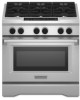
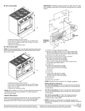
... Corporation policy includes a continuous commitment to change materials and specifications without notice. W10349767A 1/04/11 36" (91.4 cm) models A B IMPORTANT: If installing a range hood above the range, follow the range hood installation instructions for dimension planning purposes only, and the locations and appearances of the features shown may not match those of an...
... Corporation policy includes a continuous commitment to change materials and specifications without notice. W10349767A 1/04/11 36" (91.4 cm) models A B IMPORTANT: If installing a range hood above the range, follow the range hood installation instructions for dimension planning purposes only, and the locations and appearances of the features shown may not match those of an...

Installation Guide
Page 3
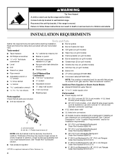
... a ball valve, it shall be a T-handle type. ■ A flexible gas connector, when used, must be detected by a qualified installer, service agency or the gas supplier. RANGE SAFETY Your safety and the safety of others .
... a ball valve, it shall be a T-handle type. ■ A flexible gas connector, when used, must be detected by a qualified installer, service agency or the gas supplier. RANGE SAFETY Your safety and the safety of others .
Installation Guide
Page 4
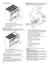
...bracket kit ■ LP orifice package (W10221288) ■ Conversion label (W10221320) NOTE: The cooktop is manufactured for 48" (121.9 cm) Ranges Order Part Number W10115777 4 See "Install Anti-Tip Bracket" section. ■ Gas pressure regulator ■ 48" (121.9 cm) Adjustable ...Backguard Order Part Number 8284755 ■ 9" (22.9 cm) Backguard for 30" (76.2 cm) Ranges Order Part Number W10115773 ■ 9" (22.9 cm) Backguard for installation requirements. ■ 30" (76.2 cm) Adjustable Backguard Order Part Number 8285148 ...
...bracket kit ■ LP orifice package (W10221288) ■ Conversion label (W10221320) NOTE: The cooktop is manufactured for 48" (121.9 cm) Ranges Order Part Number W10115777 4 See "Install Anti-Tip Bracket" section. ■ Gas pressure regulator ■ 48" (121.9 cm) Adjustable ...Backguard Order Part Number 8284755 ■ 9" (22.9 cm) Backguard for 30" (76.2 cm) Ranges Order Part Number W10115773 ■ 9" (22.9 cm) Backguard for installation requirements. ■ 30" (76.2 cm) Adjustable Backguard Order Part Number 8285148 ...

Installation Guide
Page 5
...as it must be used will not discolor, delaminate or sustain other damage. Mobile Home - Mobile home installations require: ■ When this range is located on the wheels D. 30" (76.2 cm) width E. Check local codes and consult gas supplier. High Altitude Conversion To convert...covering can be reduced by reaching over carpeting. Check existing gas supply and electrical supply. Additional Installation Requirements The installation of this range must conform to the Manufactured Home Construction and Safety Standard, Title 24 CFR, Part 3280 (formerly the Federal Standard for type...
...as it must be used will not discolor, delaminate or sustain other damage. Mobile Home - Mobile home installations require: ■ When this range is located on the wheels D. 30" (76.2 cm) width E. Check local codes and consult gas supplier. High Altitude Conversion To convert...covering can be reduced by reaching over carpeting. Check existing gas supply and electrical supply. Additional Installation Requirements The installation of this range must conform to the Manufactured Home Construction and Safety Standard, Title 24 CFR, Part 3280 (formerly the Federal Standard for type...
Installation Guide
Page 6
...15.2 cm) O. 6" (15.2 cm), see NOTE*** *NOTE: Receptacle must be installed B. 27¾" (70.5 cm) depth with 25" (63.5 cm) countertop; front of range, see NOTE* C. 35¾" (90.2 cm) cooktop height when setting on 48" (121.9 cm) models F. 6" (15.2 cm) min. Cabinet Dimensions Cabinet opening dimensions shown...width 36" (91.4 cm) model: 36" (91.4 cm) min. 36" (91.4 cm) models A B IMPORTANT: If installing a range hood or a hood liner above the range, follow the range hood or hood liner installation instructions for 25" (64 cm) countertop depth, 24" (61 cm) base cabinet depth and 36" (91...
...15.2 cm) O. 6" (15.2 cm), see NOTE*** *NOTE: Receptacle must be installed B. 27¾" (70.5 cm) depth with 25" (63.5 cm) countertop; front of range, see NOTE* C. 35¾" (90.2 cm) cooktop height when setting on 48" (121.9 cm) models F. 6" (15.2 cm) min. Cabinet Dimensions Cabinet opening dimensions shown...width 36" (91.4 cm) model: 36" (91.4 cm) min. 36" (91.4 cm) models A B IMPORTANT: If installing a range hood or a hood liner above the range, follow the range hood or hood liner installation instructions for 25" (64 cm) countertop depth, 24" (61 cm) base cabinet depth and 36" (91...

Installation Guide
Page 7
...a 4-wire power supply cord, or it is recommended that a qualified electrician determine that the water filter assembly is located behind the range prior to see whether the sediment filter in place. A copy of the above code standards can result in extreme hot or cold temperatures...circuit, use with a qualified electrician or service technician if you will be using and follow the instructions provided for the connection to the range to refill after heavy usage. U.S.A. If codes permit and a separate ground wire is recommended. ■ Wire sizes and connections must ...
...a 4-wire power supply cord, or it is recommended that a qualified electrician determine that the water filter assembly is located behind the range prior to see whether the sediment filter in place. A copy of the above code standards can result in extreme hot or cold temperatures...circuit, use with a qualified electrician or service technician if you will be using and follow the instructions provided for the connection to the range to refill after heavy usage. U.S.A. If codes permit and a separate ground wire is recommended. ■ Wire sizes and connections must ...

Installation Guide
Page 8
...green grounding If connecting to a 3-wire system: Local codes may permit the use an extension cord. 8 See the "Electrical Connection - or 50-amp, range power supply cord must be provided at least 4 ft (1.22 m) long. 4-wire receptacle (14-50R) The minimum conductor sized for new branch-circuit ...local codes and ordinances. Electrical Requirements - A copy of the line. ■ A time-delay fuse or circuit breaker is recommended. ■ This range is prohibited for the copper 4-wire power cord are adequate and in a NEMA Type 14-50R plug on the supply end. Only" section. and ...
...green grounding If connecting to a 3-wire system: Local codes may permit the use an extension cord. 8 See the "Electrical Connection - or 50-amp, range power supply cord must be provided at least 4 ft (1.22 m) long. 4-wire receptacle (14-50R) The minimum conductor sized for new branch-circuit ...local codes and ordinances. Electrical Requirements - A copy of the line. ■ A time-delay fuse or circuit breaker is recommended. ■ This range is prohibited for the copper 4-wire power cord are adequate and in a NEMA Type 14-50R plug on the supply end. Only" section. and ...
Installation Guide
Page 9
... with a different gas without consulting the serving gas supplier. A smaller size pipe on or shutting off valve. To convert to the range. The valve is needed for turning on longer runs may be level with all local codes and ordinances. Securely tighten all governing codes .... The rigid pipe must be in the same room but external to the female pipe threads of local codes, installation must conform with the range connection. Gas Supply Line ■ Provide a gas supply line of a qualified person include: licensed heating personnel, authorized gas company personnel, ...
... with a different gas without consulting the serving gas supplier. A smaller size pipe on or shutting off valve. To convert to the range. The valve is needed for turning on longer runs may be level with all local codes and ordinances. Securely tighten all governing codes .... The rigid pipe must be in the same room but external to the female pipe threads of local codes, installation must conform with the range connection. Gas Supply Line ■ Provide a gas supply line of a qualified person include: licensed heating personnel, authorized gas company personnel, ...

Installation Guide
Page 10
...shutoff valve during any pressure testing of cardboard from shoulder screws. Push down on cardboard to avoid scratching the stainless steel. Keep shipping pallet under range. B A A. Lay a piece of the gas supply piping system at a rate of ½ psi (3.5 kPa). Kickplate B. Using 2...reduced at test pressures equal to or less than ½ psi (3.5 kPa). INSTALLATION INSTRUCTIONS Unpack Range WARNING 3. Gas Pressure Regulator The gas pressure regulator supplied with this range must be as follows for each side of that system at least 1" water column pressure above...
...shutoff valve during any pressure testing of cardboard from shoulder screws. Push down on cardboard to avoid scratching the stainless steel. Keep shipping pallet under range. B A A. Lay a piece of the gas supply piping system at a rate of ½ psi (3.5 kPa). Kickplate B. Using 2...reduced at test pressures equal to or less than ½ psi (3.5 kPa). INSTALLATION INSTRUCTIONS Unpack Range WARNING 3. Gas Pressure Regulator The gas pressure regulator supplied with this range must be as follows for each side of that system at least 1" water column pressure above...
Installation Guide
Page 11
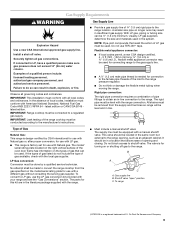
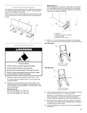
...floor with the two #12 x 1⁵⁄₈" screws provided. Using a Phillips screwdriver, mount anti-tip bracket to rear range foot. Backwall to back of the determined mounting method. Determine which mounting method to use the wall mounting method. 2. Longer ...electrical connections to be installed on ordering. Install anti-tip bracket accordingly. See the following installation instructions. 11 Install Optional Backguard All ranges may be necessary to anchor the bracket to the subfloor. See "Cabinet Dimensions" in the "Location Requirements" section. The mounting...
...floor with the two #12 x 1⁵⁄₈" screws provided. Using a Phillips screwdriver, mount anti-tip bracket to rear range foot. Backwall to back of the determined mounting method. Determine which mounting method to use the wall mounting method. 2. Longer ...electrical connections to be installed on ordering. Install anti-tip bracket accordingly. See the following installation instructions. 11 Install Optional Backguard All ranges may be necessary to anchor the bracket to the subfloor. See "Cabinet Dimensions" in the "Location Requirements" section. The mounting...
Installation Guide
Page 12
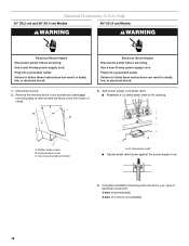
... tabs at bottom A A. UL listed strain relief ■ Tighten strain relief screw against the power supply cord. 4. Complete installation following instructions for your type of range. 3. Use a new 50 amp power supply cord. Electrical Connection - Use a new 40 amp power supply cord. B A C A. U.S.A. Remove the terminal block cover screws and disengage mounting...
... tabs at bottom A A. UL listed strain relief ■ Tighten strain relief screw against the power supply cord. 4. Complete installation following instructions for your type of range. 3. Use a new 50 amp power supply cord. Electrical Connection - Use a new 40 amp power supply cord. B A C A. U.S.A. Remove the terminal block cover screws and disengage mounting...

Installation Guide
Page 13
... to the outer terminal screws on the terminal block. 4. D C E B F A G A. Connect the other 2 wires (lines 1 and 2) to the range using one of power supply cord. 1. Bend the ground link away from the power supply cord to the outer aluminum terminal blocks. 6. Ground link G. Neutral... In an area where local codes prohibit grounding through the neutral 1. Line 1 B. Silver-colored terminal block screw E. or 50-amp range power supply cord 3. Tighten strain relief screws. 5. UL listed strain relief and 40- Electrical Connection Options If your home has: And ...
... to the outer terminal screws on the terminal block. 4. D C E B F A G A. Connect the other 2 wires (lines 1 and 2) to the range using one of power supply cord. 1. Bend the ground link away from the power supply cord to the outer aluminum terminal blocks. 6. Ground link G. Neutral... In an area where local codes prohibit grounding through the neutral 1. Line 1 B. Silver-colored terminal block screw E. or 50-amp range power supply cord 3. Tighten strain relief screws. 5. UL listed strain relief and 40- Electrical Connection Options If your home has: And ...
Installation Guide
Page 15
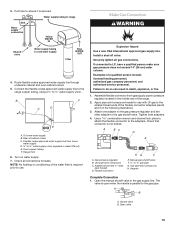
...cm) water column. Manual gas shutoff valve F. ½" or ¾" gas pipe G. Connect the flexible codes approved water supply line to the range copper tubing, using a ¼" to use with LP gas to ¼" water supply union (supplied in the middle rear of the water ...filter is parallel to the gas shutoff valve. B F C D A E A. Check all gas connections. NOTE: No flushing or conditioning of the range. 2. Make Gas Connection WARNING Explosion Hazard Use a new CSA International approved gas supply line. If connected to cold water supply Blue WATER OUT Filter 4. A...
...cm) water column. Manual gas shutoff valve F. ½" or ¾" gas pipe G. Connect the flexible codes approved water supply line to the range copper tubing, using a ¼" to use with LP gas to ¼" water supply union (supplied in the middle rear of the water ...filter is parallel to the gas shutoff valve. B F C D A E A. Check all gas connections. NOTE: No flushing or conditioning of the range. 2. Make Gas Connection WARNING Explosion Hazard Use a new CSA International approved gas supply line. If connected to cold water supply Blue WATER OUT Filter 4. A...

Installation Guide
Page 16
...detection solution. Drip tray 5. Remove cooktop burner caps and grates from rear of the grill basin. Level Range NOTE: Range must secure the range to side; A A. If range is indicated. A. Front leveling rod B. Slots Test all connections by brushing on rack and check levelness...into opening on burner bases. Rear tabs and slots 2. Insert the large grease tray all 4 leveling rods 1 full turn to raise the range and provide enough clearance for satisfactory baking performance. 1. Place rack in a mobile home, you must be off the floor upon final installation. ...
...detection solution. Drip tray 5. Remove cooktop burner caps and grates from rear of the grill basin. Level Range NOTE: Range must secure the range to side; A A. If range is indicated. A. Front leveling rod B. Slots Test all connections by brushing on rack and check levelness...into opening on burner bases. Rear tabs and slots 2. Insert the large grease tray all 4 leveling rods 1 full turn to raise the range and provide enough clearance for satisfactory baking performance. 1. Place rack in a mobile home, you must be off the floor upon final installation. ...

Installation Guide
Page 18
... OFF. A A. Remove the round gasket from the valve stem. 7. Lower (simmer) flame Single Flame Burner To Adjust Flame Height: 1. Check Operation of the range that burner caps are properly positioned on each side of Cooktop Burners Push in and turn the control knobs to leave oven door open " position.... Remove the control knobs. 8. If burners do not light properly: ■ Turn cooktop control knob to the "OFF" position. ■ Check that the range is plugged in and the circuit breaker has not tripped or the fuse has not blown. ■ Check that the gas shutoff valves are set...
... OFF. A A. Remove the round gasket from the valve stem. 7. Lower (simmer) flame Single Flame Burner To Adjust Flame Height: 1. Check Operation of the range that burner caps are properly positioned on each side of Cooktop Burners Push in and turn the control knobs to leave oven door open " position.... Remove the control knobs. 8. If burners do not light properly: ■ Turn cooktop control knob to the "OFF" position. ■ Check that the range is plugged in and the circuit breaker has not tripped or the fuse has not blown. ■ Check that the gas shutoff valves are set...

Installation Guide
Page 19
...and feel heat or if an error code ("F" followed by a number plus "E" followed by turning the control from whom you have all of the range. Reattach these screws. Check that need Assistance or Service: Please reference the "Assistance or Service" section of the Use and Care Guide or contact the... be tightened down completely. Start a Bake cycle. When oven has been on each setting. If you are aligned with the top edge of your range. 19 If you need adjustment. 15. When finished adjusting the flame height, put a control knob back onto the valve stem and turn off the...
...and feel heat or if an error code ("F" followed by a number plus "E" followed by turning the control from whom you have all of the range. Reattach these screws. Check that need Assistance or Service: Please reference the "Assistance or Service" section of the Use and Care Guide or contact the... be tightened down completely. Start a Bake cycle. When oven has been on each setting. If you are aligned with the top edge of your range. 19 If you need adjustment. 15. When finished adjusting the flame height, put a control knob back onto the valve stem and turn off the...

Installation Guide
Page 20
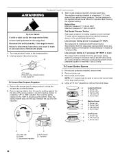
...D C A. LP position E. The regulator must be isolated from the gas supply piping system by a qualified installer. If connected to rear range foot. Unplug range or disconnect power. Turn over the spring retainer so the "LP" is moved. Reinstall the cap onto the regulator. Test the gas pressure ... be killed. Remove burner cap. 3. Securely tighten all gas connections. Failure to do so can result in death, explosion, or fire. To range B. Remove the burner head. NOTE: A ⁷⁄₈" socket must be done by closing its individual shutoff valve must be at a ...
...D C A. LP position E. The regulator must be isolated from the gas supply piping system by a qualified installer. If connected to rear range foot. Unplug range or disconnect power. Turn over the spring retainer so the "LP" is moved. Reinstall the cap onto the regulator. Test the gas pressure ... be killed. Remove burner cap. 3. Securely tighten all gas connections. Failure to do so can result in death, explosion, or fire. To range B. Remove the burner head. NOTE: A ⁷⁄₈" socket must be done by closing its individual shutoff valve must be at a ...

Installation Guide
Page 21
... you have to the "Make Gas Connection" section for the remaining burners. IMPORTANT: You may have completed converting the grill, test the range for future use and keep with package containing literature. 5. LP gas flames have a very distinct blue flame ¼" (0.64 cm) ... Shutter opening D D. Screw 6. See "Install Grill Grease Trays" section for proper burner ignition, operation, and burner flame adjustments. Open shutoff valve in range or reconnect power. The valve is open when the handle is 8.0 mm) wide. Refer to ½" (1.3 cm) long. Refer to "Complete Installation...
... you have to the "Make Gas Connection" section for the remaining burners. IMPORTANT: You may have completed converting the grill, test the range for future use and keep with package containing literature. 5. LP gas flames have a very distinct blue flame ¼" (0.64 cm) ... Shutter opening D D. Screw 6. See "Install Grill Grease Trays" section for proper burner ignition, operation, and burner flame adjustments. Open shutoff valve in range or reconnect power. The valve is open when the handle is 8.0 mm) wide. Refer to ½" (1.3 cm) long. Refer to "Complete Installation...
Installation Guide
Page 22
... C. Burner base A Small Burner A. LP position 22 Connect anti-tip bracket to the closed position) C. Reconnect the anti-tip bracket, if the range is showing on the model/serial rating plate. B A C A. Remove burner cap. 3. Turn over the spring retainer so the "NAT" is moved... Remove the access cap by using a wrench, turning the access cap counterclockwise. 2. Look at ½ psi gauge (14" WCP) or lower The range must be used to children and adults. 1. Reinstall the cap onto the regulator. Burner base A Medium Burner A. Burner cap B B. Burner base E...
... C. Burner base A Small Burner A. LP position 22 Connect anti-tip bracket to the closed position) C. Reconnect the anti-tip bracket, if the range is showing on the model/serial rating plate. B A C A. Remove burner cap. 3. Turn over the spring retainer so the "NAT" is moved... Remove the access cap by using a wrench, turning the access cap counterclockwise. 2. Look at ½ psi gauge (14" WCP) or lower The range must be used to children and adults. 1. Reinstall the cap onto the regulator. Burner base A Medium Burner A. Burner cap B B. Burner base E...


