User Guide
Page 2
... scanner on 3-1 Turning the scanner off 3-3 Starting and stopping scanning 3-3 Document preparation 3-3 Adjusting the input elevator 3-5 Adjusting the side guides 3-5 Selecting your feeding position 3-5 Locking the side guides 3-5 Adjusting the height of the input elevator 3-6 Adjusting the input tray for document length 3-6 Installing the document extender 3-7 Output tray options 3-7 Adjusting the output tray 3-7 Adjusting the side guides 3-7 Adjusting the output tray for document...
... scanner on 3-1 Turning the scanner off 3-3 Starting and stopping scanning 3-3 Document preparation 3-3 Adjusting the input elevator 3-5 Adjusting the side guides 3-5 Selecting your feeding position 3-5 Locking the side guides 3-5 Adjusting the height of the input elevator 3-6 Adjusting the input tray for document length 3-6 Installing the document extender 3-7 Output tray options 3-7 Adjusting the output tray 3-7 Adjusting the side guides 3-7 Adjusting the output tray for document...
User Guide
Page 4
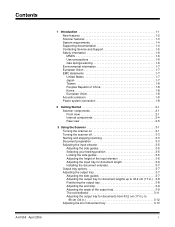
...5-2 Supplies, consumables and accessories 5-3 Ordering parts 5-3 Cleaning procedures 5-4 Cleaning the OCP touchscreen 5-4 Vacuuming the output tray and input elevator 5-4 Cleaning the rollers 5-5 Vacuuming the transport area 5-9 Vacuuming under the background strips 5-9 ... message listing 6-10 Contacting Service 6-11 Problem solving 6-12 Appendix A Accessories A-1 Kodak Ultralightweight Paper Feed Module A-1 Kodak White Background Accessory A-1 Kodak Manual Feeder A-1 Kodak High Resolution Printer Accessory A-1 Appendix B Specifications B-1 A-61555 April 2009 iii basic...
...5-2 Supplies, consumables and accessories 5-3 Ordering parts 5-3 Cleaning procedures 5-4 Cleaning the OCP touchscreen 5-4 Vacuuming the output tray and input elevator 5-4 Cleaning the rollers 5-5 Vacuuming the transport area 5-9 Vacuuming under the background strips 5-9 ... message listing 6-10 Contacting Service 6-11 Problem solving 6-12 Appendix A Accessories A-1 Kodak Ultralightweight Paper Feed Module A-1 Kodak White Background Accessory A-1 Kodak Manual Feeder A-1 Kodak High Resolution Printer Accessory A-1 Appendix B Specifications B-1 A-61555 April 2009 iii basic...

User Guide
Page 5
includes information on how to support the Kodak i1800 Series Scanners. provides a description of the optional accessories that can be purchased to prepare your documents for scanning, input elevator, output tray and workspace table adjustments, scanning your documents and using the touchscreen operator control panel. Appendix B, Specifications - Chapter 2, Getting Started - Chapter 4, Using the Enhanced Printer and Patch...
includes information on how to support the Kodak i1800 Series Scanners. provides a description of the optional accessories that can be purchased to prepare your documents for scanning, input elevator, output tray and workspace table adjustments, scanning your documents and using the touchscreen operator control panel. Appendix B, Specifications - Chapter 2, Getting Started - Chapter 4, Using the Enhanced Printer and Patch...
User Guide
Page 14
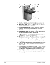
... in document stacking. 12 Printer access cover - See Chapter 3, Using the Scanner for changing printer positions and maintenance. 13 Top access cover - The workspace table can be raised or lowered approximately 10 inches up the POD release latch when you need to provide when placing a call Kodak Service. 9 POD release latch - The output tray width...
... in document stacking. 12 Printer access cover - See Chapter 3, Using the Scanner for changing printer positions and maintenance. 13 Top access cover - The workspace table can be raised or lowered approximately 10 inches up the POD release latch when you need to provide when placing a call Kodak Service. 9 POD release latch - The output tray width...
User Guide
Page 18
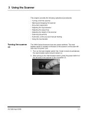
... operational procedures: • Turning on/off the scanner • Starting and stopping the scanner • Document preparation • Adjusting the input elevator • Adjusting the output tray • Adjusting the height of the scanner • Scanning documents • Automatic, continuous and manual feeding • Using the touchscreen Turning the scanner on the lower leftside near the power cord...
... operational procedures: • Turning on/off the scanner • Starting and stopping the scanner • Document preparation • Adjusting the input elevator • Adjusting the output tray • Adjusting the height of the scanner • Scanning documents • Automatic, continuous and manual feeding • Using the touchscreen Turning the scanner on the lower leftside near the power cord...
User Guide
Page 24
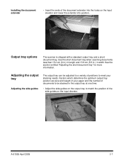
... side guides on the input elevator and lower the extender into position. A-61555 April 2009 3-7 See the section entitled "Adjusting the short document tray" for more information. Output tray options The scanner is shipped with a standard output tray and a short document tray. Installing the document extender • Insert the ends of the document extender into the holes on the input elevator.
... side guides on the input elevator and lower the extender into position. A-61555 April 2009 3-7 See the section entitled "Adjusting the short document tray" for more information. Output tray options The scanner is shipped with a standard output tray and a short document tray. Installing the document extender • Insert the ends of the document extender into the holes on the input elevator.

User Guide
Page 25
... as desired. 3-8 A-61555 April 2009 Position Stacking capacity 1 Up to 250 documents 2 Up to 500 documents 3 Up to 43.2 cm (17 in.) Adjusting for document length involves selecting an output tray position and angle, positioning the end stop, or removing the end stop 35.6... 43.2 cm (17 in.) Positioning the output tray There are three positions that the output tray can be placed in. 1 2 3 1. Adjusting the output tray for document lengths up to 500 documents Maximum document length with end stop and installing a document extender. Reviewing the following table will help ...
... as desired. 3-8 A-61555 April 2009 Position Stacking capacity 1 Up to 250 documents 2 Up to 500 documents 3 Up to 43.2 cm (17 in.) Adjusting for document length involves selecting an output tray position and angle, positioning the end stop, or removing the end stop 35.6... 43.2 cm (17 in.) Positioning the output tray There are three positions that the output tray can be placed in. 1 2 3 1. Adjusting the output tray for document lengths up to 500 documents Maximum document length with end stop and installing a document extender. Reviewing the following table will help ...

User Guide
Page 26
Lift the front of the detent positions. 1 2 3 4 1. Adjusting the end stop Adjust the output tray end stop to adjusting the back of the output tray, you can adjust the front of the tray by swinging the height adjustment wire out from underneath the output tray and placing it in one of the output tray. A-61555 April 2009 3-9 Adjusting the angle of the output tray In addition to slightly longer than the longest document being fed.
Lift the front of the detent positions. 1 2 3 4 1. Adjusting the end stop Adjust the output tray end stop to adjusting the back of the output tray, you can adjust the front of the tray by swinging the height adjustment wire out from underneath the output tray and placing it in one of the output tray. A-61555 April 2009 3-9 Adjusting the angle of the output tray In addition to slightly longer than the longest document being fed.

User Guide
Page 27
2. Swing the height adjustment wire out from underneath the output tray and insert it into position and lower the output tray. 3-10 A-61555 April 2009 When finished using the output tray in this position, tuck the height adjustment wire back into one of the grooves on the printer access cover. 3.
2. Swing the height adjustment wire out from underneath the output tray and insert it into position and lower the output tray. 3-10 A-61555 April 2009 When finished using the output tray in this position, tuck the height adjustment wire back into one of the grooves on the printer access cover. 3.

User Guide
Page 29
Remove the end stop. 2. Three sizes of the document extender into the holes on the output tray and lower the extender into position. 3-12 A-61555 April 2009 Insert the ends of document extenders are available for documents from 43.2 cm (17 in.) to 86 cm (34 in.) Documents longer than 17 inches require a document extender. See the section entitled, "Ordering parts" in Chapter 5 or contact your Kodak Field Engineer at 1-800-3KODAK3 (1-800-356-3253). 1. Adjusting the output tray for scanning documents from 43.2 cm (17 in.) to 86 cm (34 in.).
Remove the end stop. 2. Three sizes of the document extender into the holes on the output tray and lower the extender into position. 3-12 A-61555 April 2009 Insert the ends of document extenders are available for documents from 43.2 cm (17 in.) to 86 cm (34 in.) Documents longer than 17 inches require a document extender. See the section entitled, "Ordering parts" in Chapter 5 or contact your Kodak Field Engineer at 1-800-3KODAK3 (1-800-356-3253). 1. Adjusting the output tray for scanning documents from 43.2 cm (17 in.) to 86 cm (34 in.).

User Guide
Page 30
Slide the short document tray on the output tray. 2. Adjust the sides guides as necessary. A-61555 April 2009 3-13 Adjusting the short document tray 1. Remove the end stop on the rail of the output tray and push it up to the desired position to accommodate your documents. 3.
Slide the short document tray on the output tray. 2. Adjust the sides guides as necessary. A-61555 April 2009 3-13 Adjusting the short document tray 1. Remove the end stop on the rail of the output tray and push it up to the desired position to accommodate your documents. 3.

User Guide
Page 45
... poor paper quality • you want to improve paper stacking in the output tray • you are scanning batches of mixed-size documents NOTES: • Fragile Feed Mode can only be enabled when the scanner is idle. • If you use the Count Only option when Fragile Feed Mode is enabled, ...• Fragile Feed Mode will be reduced by about a third. • Fragile Feed Mode has no effect on the Kodak i1840 Scanner. • No changes to be transported through the scanner at 100, 150 and 200 dpi scanning will remain enabled until it is disabled by the operator. • The throughput ...
... poor paper quality • you want to improve paper stacking in the output tray • you are scanning batches of mixed-size documents NOTES: • Fragile Feed Mode can only be enabled when the scanner is idle. • If you use the Count Only option when Fragile Feed Mode is enabled, ...• Fragile Feed Mode will be reduced by about a third. • Fragile Feed Mode has no effect on the Kodak i1840 Scanner. • No changes to be transported through the scanner at 100, 150 and 200 dpi scanning will remain enabled until it is disabled by the operator. • The throughput ...

User Guide
Page 50
... screen will display the results of the test pattern. • If the pattern is complete, you are working properly. 1. Remove the document(s) from the output tray and evaluate the appearance of the print test. 4. Touch End Job to return to see that the print cartridge is still not legible... 2009 3-33 Repeat the print test. The document(s) in the input elevator. 3. See Chapter 4, Using the Enhanced Printer and Patch Readers. − If the pattern is installed properly. Touch Print Test. Place a blank sheet(s) of paper in the output tray will be sure the ink jets in the ...
... screen will display the results of the test pattern. • If the pattern is complete, you are working properly. 1. Remove the document(s) from the output tray and evaluate the appearance of the print test. 4. Touch End Job to return to see that the print cartridge is still not legible... 2009 3-33 Repeat the print test. The document(s) in the input elevator. 3. See Chapter 4, Using the Enhanced Printer and Patch Readers. − If the pattern is installed properly. Touch Print Test. Place a blank sheet(s) of paper in the output tray will be sure the ink jets in the ...

User Guide
Page 62
Remove the output tray. 2. You can be changed manually. There are visible by a small detent on the printer rail. A-61555 April 2009 4-3 Open the print access cover. These positions are 12 horizontal print positions. Changing print positions Changing the front horizontal print position The horizontal print position can change the front or rear print position. 1.
Remove the output tray. 2. You can be changed manually. There are visible by a small detent on the printer rail. A-61555 April 2009 4-3 Open the print access cover. These positions are 12 horizontal print positions. Changing print positions Changing the front horizontal print position The horizontal print position can change the front or rear print position. 1.

User Guide
Page 63
...;-inch (1.27 cm) from the trailing edge of the document, even if the information has not been completely printed. The printer carrier slides easily along the rail. There is a small arrow on the green printer carrier. Close the printer access cover. 5. Reinstall the output tray. There are visible by a small detent on the...
...;-inch (1.27 cm) from the trailing edge of the document, even if the information has not been completely printed. The printer carrier slides easily along the rail. There is a small arrow on the green printer carrier. Close the printer access cover. 5. Reinstall the output tray. There are visible by a small detent on the...

User Guide
Page 64
... the top access cover. 6. Access the rear printer by removing the output tray and lifting the printer access cover. 2. If your application requires rear post-scan printing, the printer carrier and cable must restart the scanner. Install the ink cartridge. See the next section, "Replacing the ink...scan printing. Lift the printer carrier out of position. 4. A-61555 April 2009 4-5 Restart the scanner. 11. Moving the printer carrier and cable from the front to rear or rear to front as well as the ink cartridge. Close the printer access cover and reinstall the output tray. 5.
... the top access cover. 6. Access the rear printer by removing the output tray and lifting the printer access cover. 2. If your application requires rear post-scan printing, the printer carrier and cable must restart the scanner. Install the ink cartridge. See the next section, "Replacing the ink...scan printing. Lift the printer carrier out of position. 4. A-61555 April 2009 4-5 Restart the scanner. 11. Moving the printer carrier and cable from the front to rear or rear to front as well as the ink cartridge. Close the printer access cover and reinstall the output tray. 5.

User Guide
Page 65
Close the top access cover. 10. Install the printer carrier in the desired position. 7. Remove the output tray and open the printer access cover. 6. See the next section "Replacing the ink cartridge" for procedures. 1. Remove the printer carrier. 4. Moving the printer carrier and .... Disconnect the ribbon cable. 3. Open the top access cover. 2. Connect the ribbon cable. 8. Run a print test. 4-6 A-61555 April 2009 Install the ink cartridge. 9. Restart the scanner. 11. Close the top access cover. 5.
Close the top access cover. 10. Install the printer carrier in the desired position. 7. Remove the output tray and open the printer access cover. 6. See the next section "Replacing the ink cartridge" for procedures. 1. Remove the printer carrier. 4. Moving the printer carrier and .... Disconnect the ribbon cable. 3. Open the top access cover. 2. Connect the ribbon cable. 8. Run a print test. 4-6 A-61555 April 2009 Install the ink cartridge. 9. Restart the scanner. 11. Close the top access cover. 5.

User Guide
Page 66
Lift up the top access cover (rear position) or remove the output tray and lift the printer access cover (front position). 2. Remove the tab from the printer carrier. 4. Replacing the ink cartridge Replace the ink cartridge when: • ...
Lift up the top access cover (rear position) or remove the output tray and lift the printer access cover (front position). 2. Remove the tab from the printer carrier. 4. Replacing the ink cartridge Replace the ink cartridge when: • ...

User Guide
Page 67
6. Close the top access cover (rear position) or the printer access cover and replace the output tray (front position). 9. Press and hold the release tab on the printer carrier with the detent position. 8. NOTE: If the ribbon cable should become disconnected, snap it back into position. Run a print test. 4-8 A-61555 April 2009 Slide the printer carrier into the desired position matching the arrow on the bottom of the printer carrier and rotate the printer carrier back into position. 7.
6. Close the top access cover (rear position) or the printer access cover and replace the output tray (front position). 9. Press and hold the release tab on the printer carrier with the detent position. 8. NOTE: If the ribbon cable should become disconnected, snap it back into position. Run a print test. 4-8 A-61555 April 2009 Slide the printer carrier into the desired position matching the arrow on the bottom of the printer carrier and rotate the printer carrier back into position. 7.

User Guide
Page 70
... properly aligned before pressing the adhesive side into place. 7. Peel the backing away from the new blotter strip. 5. Remove the output tray. This will lock the drawer in the channel. Replace the output tray. Press the blotter strip firmly into the channel. 6. Repeat Steps 2 - 5 for the other blotter strip. 8. A-61555 April 2009 4-11 Align...
... properly aligned before pressing the adhesive side into place. 7. Peel the backing away from the new blotter strip. 5. Remove the output tray. This will lock the drawer in the channel. Replace the output tray. Press the blotter strip firmly into the channel. 6. Repeat Steps 2 - 5 for the other blotter strip. 8. A-61555 April 2009 4-11 Align...

