
User Guide
Page 6
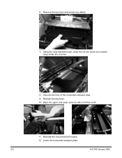
... head 5-9 Cleaning the imaging guides 5-10 Maintenance and replacement procedures 5-11 Replacing the feed module and feed module tires...........5-12 Replacing the feed module 5-13 Replacing the feed module tires 5-13 Separation roller and tires 5-15 Replacing the separation roller 5-15 Replacing the separation... roller tires 5-16 Changing the separation pad 5-16 Cleaning the feed module tires and separation roller roller tires 5-17 Replacing lamps 5-17 Replacing the imaging guides 5-20 Customizing the side guides for ...
... head 5-9 Cleaning the imaging guides 5-10 Maintenance and replacement procedures 5-11 Replacing the feed module and feed module tires...........5-12 Replacing the feed module 5-13 Replacing the feed module tires 5-13 Separation roller and tires 5-15 Replacing the separation roller 5-15 Replacing the separation... roller tires 5-16 Changing the separation pad 5-16 Cleaning the feed module tires and separation roller roller tires 5-17 Replacing lamps 5-17 Replacing the imaging guides 5-20 Customizing the side guides for ...

User Guide
Page 7
... list of external components and user precautions. Chapter 2, Using the Scanner includes information on how to prepare your documents for the Kodak i800 Series Scanners. Chapter 6, Troubleshooting/Messages provides a message listing, a...Scanner, including replacement procedures for using the Operator Control Panel. The information in this guide is for use with all of the Document Printer 1 and the Patch Reader. This chapter also instructs how to clear a document jam. Chapter 4, Document Printer and Patch Reader provides instructions for the feeder module...
... list of external components and user precautions. Chapter 2, Using the Scanner includes information on how to prepare your documents for the Kodak i800 Series Scanners. Chapter 6, Troubleshooting/Messages provides a message listing, a...Scanner, including replacement procedures for using the Operator Control Panel. The information in this guide is for use with all of the Document Printer 1 and the Patch Reader. This chapter also instructs how to clear a document jam. Chapter 4, Document Printer and Patch Reader provides instructions for the feeder module...
User Guide
Page 11
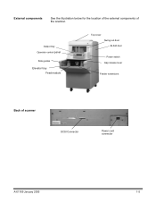
External components See the illustration below for the location of the external components of scanner SCSI Connector Power cord connector A-61169 January 2005 1-5 Output tray Operator control panel Side guides Elevator tray Feed module Top cover Swing out door Bi-fold door Power switch Gap release lever Feeder extensions Back of the scanner.
External components See the illustration below for the location of the external components of scanner SCSI Connector Power cord connector A-61169 January 2005 1-5 Output tray Operator control panel Side guides Elevator tray Feed module Top cover Swing out door Bi-fold door Power switch Gap release lever Feeder extensions Back of the scanner.
User Guide
Page 14
... is suggested that are outside of these specifications may lead to be fed under both feed module tires. Before you start scanning, make sure the documents can be transported successfully through the scanner. Best performance is very important. Documents must be arranged to have been tested with a range ... at a time. Documents may be left-, right-, or center-aligned in the most common business applications. Document preparation Kodak scanners have a common leading edge. This means the side of the paper which orientation feeds best. • A batch of the gap release lever may be...
... is suggested that are outside of these specifications may lead to be fed under both feed module tires. Before you start scanning, make sure the documents can be transported successfully through the scanner. Best performance is very important. Documents must be arranged to have been tested with a range ... at a time. Documents may be left-, right-, or center-aligned in the most common business applications. Document preparation Kodak scanners have a common leading edge. This means the side of the paper which orientation feeds best. • A batch of the gap release lever may be...
User Guide
Page 15
Multi-feed detection must be fed under both feed module tires. - The correct document preparation when using a clear document protector. - Heavier documents may be required to feed heavier paper weights. • Length: - ... - Minimum for automatic feeding of 6.4 cm (2.5 in a clear document protector. • For heavily damaged documents, a clear document protector can be used with feed module and separation tires possibly requiring more frequent tire changes) • Offset printing papers (i.e., newspapers, magazine pages) The elevator tray handles a broad range of paper weights...
Multi-feed detection must be fed under both feed module tires. - The correct document preparation when using a clear document protector. - Heavier documents may be required to feed heavier paper weights. • Length: - ... - Minimum for automatic feeding of 6.4 cm (2.5 in a clear document protector. • For heavily damaged documents, a clear document protector can be used with feed module and separation tires possibly requiring more frequent tire changes) • Offset printing papers (i.e., newspapers, magazine pages) The elevator tray handles a broad range of paper weights...
User Guide
Page 18
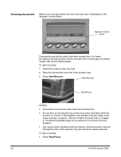
..., feed documents into the elevator tray in Chapter 6, Troubleshooting/Messages for procedures on the elevator tray and/or document extenders while the scanner is displayed on the Operator Control Panel. Press Start/Resume. To start scanning: 1. Start/Resume Stop/Pause NOTES: • Documents... (longer side as the leading edge). Scanning documents Before you scan documents, be fed under both feed module tires. Operator Control panel Documents must be fed under both feed module tires. • Do not lean on recovery from the host. 2. If this situation. •...
..., feed documents into the elevator tray in Chapter 6, Troubleshooting/Messages for procedures on the elevator tray and/or document extenders while the scanner is displayed on the Operator Control Panel. Press Start/Resume. To start scanning: 1. Start/Resume Stop/Pause NOTES: • Documents... (longer side as the leading edge). Scanning documents Before you scan documents, be fed under both feed module tires. Operator Control panel Documents must be fed under both feed module tires. • Do not lean on recovery from the host. 2. If this situation. •...
User Guide
Page 41
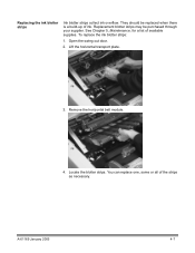
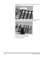
Replacement blotter strips may be replaced when there is a build-up of ink. Locate the blotter strips. Open the swing out door. 2. They should be purchased through your supplier. To replace the ink blotter strips: 1. Lift the horizontal transport plate. 3. A-61169 January 2005 4-7 Replacing the ink blotter strips Ink blotter strips collect ink overflow. See Chapter 5, Maintenance, for a list of the strips as necessary. You can replace one, some or all of available supplies. Remove the horizontal belt module. 4.
Replacement blotter strips may be replaced when there is a build-up of ink. Locate the blotter strips. Open the swing out door. 2. They should be purchased through your supplier. To replace the ink blotter strips: 1. Lift the horizontal transport plate. 3. A-61169 January 2005 4-7 Replacing the ink blotter strips Ink blotter strips collect ink overflow. See Chapter 5, Maintenance, for a list of the strips as necessary. You can replace one, some or all of available supplies. Remove the horizontal belt module. 4.
User Guide
Page 42
Close the swing out door. 4-8 A-61169 January 2005 Grasp a blotter strip and carefully pull it in the transport channel before pressing the adhesive side into the channel. 7. Discard the soiled strips. 6. 5. Lower the horizontal transport plate. 9. Install the new blotter strip. Re-insert the horizontal belt module. 8. Make sure that you align it off the transport.
Close the swing out door. 4-8 A-61169 January 2005 Grasp a blotter strip and carefully pull it in the transport channel before pressing the adhesive side into the channel. 7. Discard the soiled strips. 6. 5. Lower the horizontal transport plate. 9. Install the new blotter strip. Re-insert the horizontal belt module. 8. Make sure that you align it off the transport.
User Guide
Page 53
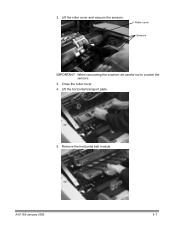
A-61169 January 2005 5-7 Lift the horizontal transport plate. 5. Roller cover Sensors IMPORTANT: When vacuuming the scanner, be careful not to scratch the sensors. 3. Lift the roller cover and vacuum the sensors. Close the roller cover. 4. 2. Remove the horizontal belt module.
A-61169 January 2005 5-7 Lift the horizontal transport plate. 5. Roller cover Sensors IMPORTANT: When vacuuming the scanner, be careful not to scratch the sensors. 3. Lift the roller cover and vacuum the sensors. Close the roller cover. 4. 2. Remove the horizontal belt module.
User Guide
Page 54
Remove the dust pan and empty any debris. 7. Wipe the upper and lower sensors with a lint-free cloth. 11. Reinstall the horizontal belt module. 12. Vacuum the floor of the horizontal transport area. 9. 6. Lower the horizontal transport plate. 5-8 A-61169 January 2005 Using the long-handled brush, clean the mirrors which are located deep inside the scanner. 8. Reinsert the dust pan. 10.
Remove the dust pan and empty any debris. 7. Wipe the upper and lower sensors with a lint-free cloth. 11. Reinstall the horizontal belt module. 12. Vacuum the floor of the horizontal transport area. 9. 6. Lower the horizontal transport plate. 5-8 A-61169 January 2005 Using the long-handled brush, clean the mirrors which are located deep inside the scanner. 8. Reinsert the dust pan. 10.
User Guide
Page 57
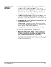
... hours of tall side guides is recommended that all the tires on the feed module and separation roller. • Exposure Lamps - replace when the imaging guides are standard with the scanner. a spacer is included with your application. Nominal tire life will be changed ...as required by the scanner, repeated image calibration failures, etc.) • Imaging Guides - Install a new feed module and separation roller at the same time. • Feed Module Separation Roller - If you install a new feed module approximately every 5th tire change tires. it...
... hours of tall side guides is recommended that all the tires on the feed module and separation roller. • Exposure Lamps - replace when the imaging guides are standard with the scanner. a spacer is included with your application. Nominal tire life will be changed ...as required by the scanner, repeated image calibration failures, etc.) • Imaging Guides - Install a new feed module and separation roller at the same time. • Feed Module Separation Roller - If you install a new feed module approximately every 5th tire change tires. it...
User Guide
Page 58
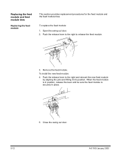
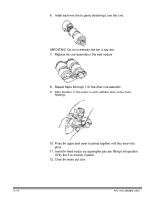
To install the new feed module: 4. To replace the feed module: 1. Replacing the feed module and feed module tires Replacing the feed module This section provides replacement procedures for the feed module and the feed module tires. Push the release lever to release the feed module. 3. Push the release lever to the right to the right and reinsert the...
To install the new feed module: 4. To replace the feed module: 1. Replacing the feed module and feed module tires Replacing the feed module This section provides replacement procedures for the feed module and the feed module tires. Push the release lever to release the feed module. 3. Push the release lever to the right to the right and reinsert the...
User Guide
Page 59
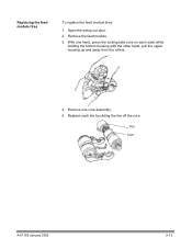
Open the swing out door. 2. Tire Core A-61169 January 2005 5-13 Remove one on each tire by sliding the tire off the core. Replace each side) while holding the bottom housing with the other hand, pull the upper housing up and away from the rollers. 4. With one hand, press the locking tabs (one core assembly. 5. Remove the feed module. 3. Replacing the feed module tires To replace the feed module tires: 1.
Open the swing out door. 2. Tire Core A-61169 January 2005 5-13 Remove one on each tire by sliding the tire off the core. Replace each side) while holding the bottom housing with the other hand, pull the upper housing up and away from the rollers. 4. With one hand, press the locking tabs (one core assembly. 5. Remove the feed module. 3. Replacing the feed module tires To replace the feed module tires: 1.
User Guide
Page 60
Press the upper and lower housings together until they snap into position. Repeat Steps 4 through 7 for the other core assembly. 9. it is securely in the feed module. 8. IMPORTANT: Do not overstretch the tire; Align the tabs on the upper housing with the slots on the lower housing. 10. Install each new tire by aligning the pins and fitting it over the core. Insert the feed module by gently stretching it into place. 11. 6. Replace the core assembly in place. 12. Close the swing out door. 5-14 A-61169 January 2005 Verify that it may tear. 7.
Press the upper and lower housings together until they snap into position. Repeat Steps 4 through 7 for the other core assembly. 9. it is securely in the feed module. 8. IMPORTANT: Do not overstretch the tire; Align the tabs on the upper housing with the slots on the lower housing. 10. Install each new tire by aligning the pins and fitting it over the core. Insert the feed module by gently stretching it into place. 11. 6. Replace the core assembly in place. 12. Close the swing out door. 5-14 A-61169 January 2005 Verify that it may tear. 7.

User Guide
Page 63
... may be performed daily. Replace all residue is turned off and you have been operating are four identical lamps in the scanner. Remove the feed module. 3. CAUTION: Lamps that have allowed the lamps to separate properly when feeding. 1. Remove the feed... the separation roller. 8. Daily cleaning of the feed module tires and separation roller tires prevent ink, toner, dust and paper contaminates from the tires. 6. Close the swing out door. Before attempting to replace the lamps, make sure the scanner is removed from collecting on throughput and document type. ...
... may be performed daily. Replace all residue is turned off and you have been operating are four identical lamps in the scanner. Remove the feed module. 3. CAUTION: Lamps that have allowed the lamps to separate properly when feeding. 1. Remove the feed... the separation roller. 8. Daily cleaning of the feed module tires and separation roller tires prevent ink, toner, dust and paper contaminates from the tires. 6. Close the swing out door. Before attempting to replace the lamps, make sure the scanner is removed from collecting on throughput and document type. ...

User Guide
Page 71
...States by calling DI Supply at 1-888-247-1234 or contact your local Kodak dealer. includes 2 feed modules, 2 separation roller assemblies, 10 pre-separation pads, 50 replacement tires Imaging Guide Set - includes 2 feed modules, 2 separation roller assemblies, 10 pre-separation pads, 50 replacement tires. Description... Ink Cartridge Carrier for i800/3000/4000 Scanners Printer Ink Cartridges for Scanner Series 3000/4000/7000/9000/i800 Staticide Wipes (Qty 144) White Imaging Lamp for Scanner Series 3000/5000/7000/i800 (1/carton) Kodak Feeder Kit for i800 Series Scanners - This kit is used as a...
...States by calling DI Supply at 1-888-247-1234 or contact your local Kodak dealer. includes 2 feed modules, 2 separation roller assemblies, 10 pre-separation pads, 50 replacement tires Imaging Guide Set - includes 2 feed modules, 2 separation roller assemblies, 10 pre-separation pads, 50 replacement tires. Description... Ink Cartridge Carrier for i800/3000/4000 Scanners Printer Ink Cartridges for Scanner Series 3000/4000/7000/9000/i800 Staticide Wipes (Qty 144) White Imaging Lamp for Scanner Series 3000/5000/7000/i800 (1/carton) Kodak Feeder Kit for i800 Series Scanners - This kit is used as a...

User Guide
Page 77
...power-down sequence on again. See Chapter 5, Maintenance, "Cleaning the Transport area" for correct procedures. See Chapter 5, Maintenance "Replacing the feed module" for cleaning procedures. See Chapter 5, Maintenance, for instructions. Clean the S2 sensor The S2 (post-imaging) sensor is dirty. Refeed all ...The self-test of this chapter for which images were not obtained. See "Clearing the document path", earlier in the scanner. The feed module may not be installed or may not be installed properly. If cropping is stuck in until fully seated. Message Message...
...power-down sequence on again. See Chapter 5, Maintenance, "Cleaning the Transport area" for correct procedures. See Chapter 5, Maintenance "Replacing the feed module" for cleaning procedures. See Chapter 5, Maintenance, for instructions. Clean the S2 sensor The S2 (post-imaging) sensor is dirty. Refeed all ...The self-test of this chapter for which images were not obtained. See "Clearing the document path", earlier in the scanner. The feed module may not be installed or may not be installed properly. If cropping is stuck in until fully seated. Message Message...

User Guide
Page 82
... problems you may encounter when using the Kodak i800 Series Scanners. Make sure that the new lamps have been on . • all doors are completely closed. • the scanner is enabled from the host. • documents are making contact with the feed module. • for thicker documents, press ...8226; you calibrate. A-61169 January 2005 6-11 Image quality is on for at least 10 minutes before you check the feed module and separation roller for signs of the scanner. • the wall outlet is not defective (call a licensed electrician). • the power switch is on at least 3...
... problems you may encounter when using the Kodak i800 Series Scanners. Make sure that the new lamps have been on . • all doors are completely closed. • the scanner is enabled from the host. • documents are making contact with the feed module. • for thicker documents, press ...8226; you calibrate. A-61169 January 2005 6-11 Image quality is on for at least 10 minutes before you check the feed module and separation roller for signs of the scanner. • the wall outlet is not defective (call a licensed electrician). • the power switch is on at least 3...
User Guide
Page 83
... You may have leaned on for the length of batched documents, etc. • the sensors are clean. • the separation roller, feed module, and pre-separation pad are clean and properly installed. • the transport rollers are clean. • the imaging guides are properly installed. ...Make sure that: • the elevator tray extenders are pulled out to calibrate the scanner after installing the new lamps. Be sure to provide support for long documents. • the output tray is adjusted for 10 minutes before...
... You may have leaned on for the length of batched documents, etc. • the sensors are clean. • the separation roller, feed module, and pre-separation pad are clean and properly installed. • the transport rollers are clean. • the imaging guides are properly installed. ...Make sure that: • the elevator tray extenders are pulled out to calibrate the scanner after installing the new lamps. Be sure to provide support for long documents. • the output tray is adjusted for 10 minutes before...
User Guide
Page 84
Clean the feed module rollers, separation rollers and transport rollers (see Chapter 5, Maintenance). • Be sure when you calibrate the scanner that you are having problems printing on the image Possible Solutions Make sure the output tray is installed properly. ... that the printer has been enabled through the documents • The imaging guides may be dirty. Use the calibration target provided with your scanner. For procedures see Chapter 5, Maintenance, "Cleaning the imaging guides". A-61169 January 2005 6-13 The document printer is not empty. Additional ...
Clean the feed module rollers, separation rollers and transport rollers (see Chapter 5, Maintenance). • Be sure when you calibrate the scanner that you are having problems printing on the image Possible Solutions Make sure the output tray is installed properly. ... that the printer has been enabled through the documents • The imaging guides may be dirty. Use the calibration target provided with your scanner. For procedures see Chapter 5, Maintenance, "Cleaning the imaging guides". A-61169 January 2005 6-13 The document printer is not empty. Additional ...