
PRESCRIBE Commands Command Reference Manual Rev 4.8
Page 172
... = Normal 1 12 = Normal 2 13 = Normal 3 14 = Heavy 1 15 = Heavy 2 16 = Heavy 3 17 = Extra heavy 162 set MeDia type ATtribute Format MDAT [media-type[, paper-weight, fuser-mode, duplex[, density]]]; PRESCRIBE Command Reference MDAT -
... = Normal 1 12 = Normal 2 13 = Normal 3 14 = Heavy 1 15 = Heavy 2 16 = Heavy 3 17 = Extra heavy 162 set MeDia type ATtribute Format MDAT [media-type[, paper-weight, fuser-mode, duplex[, density]]]; PRESCRIBE Command Reference MDAT -

PRESCRIBE Commands Command Reference Manual Rev 4.8
Page 173
...media type for duplex printing or not. The paper-weight attribute affects the printing system's transfer bias, fuser-mode affects the fuser temperature, and duplex determines whether the paper with that paper type is used to their defaults. Related Command... MTYP 163 If the parameters paper-weight and fuser-mode are reset to the thick paper weight and the high fuser temperature mode, disabling the duplex printing, command: !R! MDAT fuser-mode 0 = High 1 = Middle 2 = Low 3 = Vellum duplex 0 = Enable 1 = Disable density...
...media type for duplex printing or not. The paper-weight attribute affects the printing system's transfer bias, fuser-mode affects the fuser temperature, and duplex determines whether the paper with that paper type is used to their defaults. Related Command... MTYP 163 If the parameters paper-weight and fuser-mode are reset to the thick paper weight and the high fuser temperature mode, disabling the duplex printing, command: !R! MDAT fuser-mode 0 = High 1 = Middle 2 = Low 3 = Vellum duplex 0 = Enable 1 = Disable density...
PRESCRIBE Commands Command Reference Manual Rev 4.8
Page 358
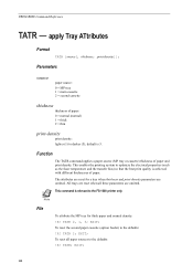
...Tray ATtributes Format TATR [source[, thickness, print-density]]; This enables the printing system to optimize the electrical properties (such as the fuser temperature and the transfer bias) so that the best print quality is relevant to the defaults: !R! This command is achieved with ...all three parameters are omitted. The attributes are reset for thick paper and normal density: !R! All trays are reset when all paper sources to the FS-1000 printer only. TATR 0, 1, 3; EXIT; TATR; Note File To attribute the MP tray for a tray when thickness and print-density parameters ...
...Tray ATtributes Format TATR [source[, thickness, print-density]]; This enables the printing system to optimize the electrical properties (such as the fuser temperature and the transfer bias) so that the best print quality is relevant to the defaults: !R! This command is achieved with ...all three parameters are omitted. The attributes are reset for thick paper and normal density: !R! All trays are reset when all paper sources to the FS-1000 printer only. TATR 0, 1, 3; EXIT; TATR; Note File To attribute the MP tray for a tray when thickness and print-density parameters ...

PRESCRIBE Commands Command Reference Manual Rev 4.8
Page 407
... priority, 116 font mode, 108, 119 saving current, 270 selection by assigning typeface, 294 Font attributes, 291 Font list, 105 printing a, 105 Font mode, 119 Fuser mode, 162, 163 G Graphics state, 228, 272 Gray pattern, 122 Grouping, 27 H Hard disk, 141, 246, 250, 256, 258 error codes, 136 I Image ...Job separation, 145 choosing first or all pages, 145 separating copies by command, 145 K KCGL pen color, 297 KIR, 304 refinement level, 304 KPDL, 287 Kyocera Image Refinement, 304 L left, 307 Lightness, 155 Line, 73, 80, 82, 87 drawing by angle, 82 drawing to absolute, 73 drawing to relative, 80...
... priority, 116 font mode, 108, 119 saving current, 270 selection by assigning typeface, 294 Font attributes, 291 Font list, 105 printing a, 105 Font mode, 119 Fuser mode, 162, 163 G Graphics state, 228, 272 Gray pattern, 122 Grouping, 27 H Hard disk, 141, 246, 250, 256, 258 error codes, 136 I Image ...Job separation, 145 choosing first or all pages, 145 separating copies by command, 145 K KCGL pen color, 297 KIR, 304 refinement level, 304 KPDL, 287 Kyocera Image Refinement, 304 L left, 307 Lightness, 155 Line, 73, 80, 82, 87 drawing by angle, 82 drawing to absolute, 73 drawing to relative, 80...

PRESCRIBE Commands Technical Reference Manual - Rev. 4.7
Page 105
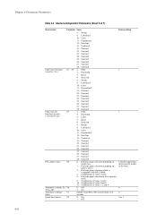
... (6 MB) Copy count C0 Number of copies to 5 (Dark) 3 Service status page D5 0: Not printed 1 1: Printed Paper jam retry timing D6 0: End of page 0 1: Fuser sensor activated 2: Fuser sensor deactivated 3: Page ejection 4: Same as 0; Error is not sent. Interface-independent Parameters Table 6.2. After a language is selected, B7=1 is ready or waiting. Error...
... (6 MB) Copy count C0 Number of copies to 5 (Dark) 3 Service status page D5 0: Not printed 1 1: Printed Paper jam retry timing D6 0: End of page 0 1: Fuser sensor activated 2: Fuser sensor deactivated 3: Page ejection 4: Same as 0; Error is not sent. Interface-independent Parameters Table 6.2. After a language is selected, B7=1 is ready or waiting. Error...
PRESCRIBE Commands Technical Reference Manual - Rev. 4.7
Page 110
... 1: On Y1 number from 000 to 6 Paper type for Envelope Feeder/ Universal Feeder PCL paper source Automatic continue for 'Press GO' Automatic continue timer Quick fuser heater Parameter Value 8: Rough 9: Letterhead 10: Color 11: Prepunched 12: Envelope 13: Cardstock 21: Custom1 22: Custom2 23: Custom3 24: Custom4 25: Custom5 26: Custom6...
... 1: On Y1 number from 000 to 6 Paper type for Envelope Feeder/ Universal Feeder PCL paper source Automatic continue for 'Press GO' Automatic continue timer Quick fuser heater Parameter Value 8: Rough 9: Letterhead 10: Color 11: Prepunched 12: Envelope 13: Cardstock 21: Custom1 22: Custom2 23: Custom3 24: Custom4 25: Custom5 26: Custom6...

FS-1028MFP/1128MFP Operation Guide Rev-3
Page 364
NOTE: The drum is hot. CAUTION: The fuser unit inside the machine is sensitive to light for more than five minutes. 10-14 OPERATION GUIDE Never expose the drum unit to light. Do not touch it, as it may result in burn injury. Remove any partially fed paper. 2 Open the front cover, and lift the developer unit together with both hands. Troubleshooting Inside the Machine 1 Pull the paper cassette all the way out of the machine. 3 Remove the drum unit from the machine by holding the green levers with the toner container out of the machine.
NOTE: The drum is hot. CAUTION: The fuser unit inside the machine is sensitive to light for more than five minutes. 10-14 OPERATION GUIDE Never expose the drum unit to light. Do not touch it, as it may result in burn injury. Remove any partially fed paper. 2 Open the front cover, and lift the developer unit together with both hands. Troubleshooting Inside the Machine 1 Pull the paper cassette all the way out of the machine. 3 Remove the drum unit from the machine by holding the green levers with the toner container out of the machine.

FS-1028MFP/1128MFP Operation Guide Rev-3
Page 365
... both ends with the toner container, back into the machine. Do not touch it, as it out. Close the front cover. OPERATION GUIDE CAUTION: The fuser unit inside the machine is hot. Troubleshooting 4 If the jammed paper appears to be pinched by rollers, pull it along the normal running direction of...
... both ends with the toner container, back into the machine. Do not touch it, as it out. Close the front cover. OPERATION GUIDE CAUTION: The fuser unit inside the machine is hot. Troubleshooting 4 If the jammed paper appears to be pinched by rollers, pull it along the normal running direction of...

FS-1028MFP/1128MFP Operation Guide Rev-3
Page 366
... jams in the rollers or difficult to remove, proceed to the next step. 10-16 OPERATION GUIDE If the original is jammed inside the fuser unit, open the fuser cover and remove the paper by pulling it out. 2 Close the rear cover, and open and close the top cover to clear the...
... jams in the rollers or difficult to remove, proceed to the next step. 10-16 OPERATION GUIDE If the original is jammed inside the fuser unit, open the fuser cover and remove the paper by pulling it out. 2 Close the rear cover, and open and close the top cover to clear the...

FS-1028MFP/1128MFP Quick Guide
Page 18
Rear Cover 1. If the paper is hot. Close the rear cover, and open the fuser cover and remove the paper by pulling it out. The machine warms up and resumes printing. 18 Open the rear cover and remove the jammed paper by pulling it out. 2. CAUTION: The fuser unit inside the machine is jammed inside the fuser unit, open and close the front cover to clear the error. Do not touch it, as it may result in burn injury. 3.
Rear Cover 1. If the paper is hot. Close the rear cover, and open the fuser cover and remove the paper by pulling it out. The machine warms up and resumes printing. 18 Open the rear cover and remove the jammed paper by pulling it out. 2. CAUTION: The fuser unit inside the machine is jammed inside the fuser unit, open and close the front cover to clear the error. Do not touch it, as it may result in burn injury. 3.

Service Manual
Page 12
... and Disassembly 1-5-1 Precautions for assembly and disassembly 1-5-1 (1) Precautions ...1-5-1 (2) Drum...1-5-1 (3) Toner ...1-5-1 (4) How to tell a genuine Kyocera Mita toner container 1-5-2 1-5-2 Outer covers ...1-5-3 (1) Detaching and refitting the left cover and right cover 1-5-3 1-5-3 Paper feed section ...Transfer/separation section ...1-5-32 (1) Detaching and refitting the transfer roller 1-5-32 1-5-8 Fuser section ...1-5-34 (1) Detaching and refitting the fuser unit 1-5-34 (2) Switching the fuser pressure ...1-5-38 1-5-9 PWBs ...1-5-39 (1) Detaching and refitting the control PWB ...
... and Disassembly 1-5-1 Precautions for assembly and disassembly 1-5-1 (1) Precautions ...1-5-1 (2) Drum...1-5-1 (3) Toner ...1-5-1 (4) How to tell a genuine Kyocera Mita toner container 1-5-2 1-5-2 Outer covers ...1-5-3 (1) Detaching and refitting the left cover and right cover 1-5-3 1-5-3 Paper feed section ...Transfer/separation section ...1-5-32 (1) Detaching and refitting the transfer roller 1-5-32 1-5-8 Fuser section ...1-5-34 (1) Detaching and refitting the fuser unit 1-5-34 (2) Switching the fuser pressure ...1-5-38 1-5-9 PWBs ...1-5-39 (1) Detaching and refitting the control PWB ...

Service Manual
Page 13
(2) Main charger unit...2-1-5 2-1-3 Optical section ...2-1-6 (1) Scanner unit ...2-1-6 (2) Image scanner unit (ISU) ...2-1-7 (3) Laser scanner unit...2-1-9 2-1-4 Developing section...2-1-11 2-1-5 Transfer/separation section ...2-1-12 2-1-6 Cleaning section ...2-1-13 2-1-7 Fuser section ...2-1-14 2-1-8 Paper exit section ...2-1-16 2-1-9 Duplex/conveying section ...2-1-18 2-1-10 DP section...2-1-19 2-2 Electrical Parts Layout 2-2-1 Electrical parts layout...2-2-1 (1) PWBs ...2-2-1 (2) Switches and sensors ...2-2-3 (3) Other ...
(2) Main charger unit...2-1-5 2-1-3 Optical section ...2-1-6 (1) Scanner unit ...2-1-6 (2) Image scanner unit (ISU) ...2-1-7 (3) Laser scanner unit...2-1-9 2-1-4 Developing section...2-1-11 2-1-5 Transfer/separation section ...2-1-12 2-1-6 Cleaning section ...2-1-13 2-1-7 Fuser section ...2-1-14 2-1-8 Paper exit section ...2-1-16 2-1-9 Duplex/conveying section ...2-1-18 2-1-10 DP section...2-1-19 2-2 Electrical Parts Layout 2-2-1 Electrical parts layout...2-2-1 (1) PWBs ...2-2-1 (2) Switches and sensors ...2-2-3 (3) Other ...

Service Manual
Page 20
Laser scanner unit (LSU) 9. Fuser section 11. Main charger unit 7. Transfer/separation section 10. Scanner section 1-1-6 Cassette 2. Paper feed/conveying section 4. Drum unit 8. Duplex/conveying section 13. Toner container 5. 2JN 1-1-3 Machine cross section Paper path 13 8 76 5 4 Paper path (option) 11 Light path 10 2 12 9 1 3 Figure 1-1-3 1. MP tray 3. Developing unit 6. Exit section 12.
Laser scanner unit (LSU) 9. Fuser section 11. Main charger unit 7. Transfer/separation section 10. Scanner section 1-1-6 Cassette 2. Paper feed/conveying section 4. Drum unit 8. Duplex/conveying section 13. Toner container 5. 2JN 1-1-3 Machine cross section Paper path 13 8 76 5 4 Paper path (option) 11 Light path 10 2 12 9 1 3 Figure 1-1-3 1. MP tray 3. Developing unit 6. Exit section 12.

Service Manual
Page 30
...list Section General Initialization Drive, paper feed, paper conveying and cooling system Optical High voltage Developing Fuser and cleaning Item No. U000 U001 U002 U004 U019 U021 U030 U031 U032 U033 U034 U051 ... drive time Performing drum refresh operation Initial setting for the developing unit Setting toner loading operation Checking the developing drive time Setting the fuser control temperature Checking the fuser temperature Initial setting* - 541/0/0/0 235/0/0/0/0/0/0 0/0/0/0/0 0 0 0/0 0/0 0/0 0/0 0 0/0/0/0/0 0/0 125/125/120 0 0 OFF/0 1/3/8/20/1/2/3 0/0/0/0/0/0/0 - *: Factory initial...
...list Section General Initialization Drive, paper feed, paper conveying and cooling system Optical High voltage Developing Fuser and cleaning Item No. U000 U001 U002 U004 U019 U021 U030 U031 U032 U033 U034 U051 ... drive time Performing drum refresh operation Initial setting for the developing unit Setting toner loading operation Checking the developing drive time Setting the fuser control temperature Checking the fuser temperature Initial setting* - 541/0/0/0 235/0/0/0/0/0/0 0/0/0/0/0 0 0 0/0 0/0 0/0 0/0 0 0/0/0/0/0 0/0 125/125/120 0 0 OFF/0 1/3/8/20/1/2/3 0/0/0/0/0/0/0 - *: Factory initial...

Service Manual
Page 61
...Initial setting 1ST TEMP T1 Stabilized temperature during printing T4 -30 to be used to prevent curling or creasing of paper, or solve a fuser problem on . Press the start key. Purpose To check if all the LEDs on the operation panel on thick paper. is displayed. ... Press the stop key. The screen for selecting a maintenance item No. Method 1. The LEDs turns off and on the operation panel light. 3. The fuser temperature and ambient temperature are displayed in centigrade (°C). Method 1. Select [EXECUTE] and press the start tempera -30 to 30 0 PRINT TEMP T3...
...Initial setting 1ST TEMP T1 Stabilized temperature during printing T4 -30 to be used to prevent curling or creasing of paper, or solve a fuser problem on . Press the start key. Purpose To check if all the LEDs on the operation panel on thick paper. is displayed. ... Press the stop key. The screen for selecting a maintenance item No. Method 1. The LEDs turns off and on the operation panel light. 3. The fuser temperature and ambient temperature are displayed in centigrade (°C). Method 1. Select [EXECUTE] and press the start tempera -30 to 30 0 PRINT TEMP T3...
Service Manual
Page 127
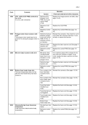
... 30 minutes, then turn machine on again. Defective control PWB. Defective control PWB. Replace the fuser unit (See page 1-5-34). Fuser heater lamp Replace the fuser unit (See page 1-5-34). mistor. Turn machine power off for continuity within the connector harness.... scanner unit) error The polygon motor ready input is not given for 6 s during the polygon motor is detected. Fuser thermistor installed incorrectly. Fuser thermal cut- installed incorrectly. Replace the laser scanner unit (See page 15-17). out triggered. Replace the image scanner...
... 30 minutes, then turn machine on again. Defective control PWB. Defective control PWB. Replace the fuser unit (See page 1-5-34). Fuser heater lamp Replace the fuser unit (See page 1-5-34). mistor. Turn machine power off for continuity within the connector harness.... scanner unit) error The polygon motor ready input is not given for 6 s during the polygon motor is detected. Fuser thermistor installed incorrectly. Fuser thermal cut- installed incorrectly. Replace the laser scanner unit (See page 15-17). out triggered. Replace the image scanner...

Service Manual
Page 128
... main power switch off/on to restart the machine. Replace the control PWB (See page 1-539). Control PWB - Replace the fuser unit (See page 1-5-34). Waste toner reservoir (drum unit) is 0 (A/D value). Defective control PWB. Replace the operation panel...Operation panel PWB communication error Defective harness between power source PWB (YC103) and high voltage PWB (YC201). Fuser thermistor installed incorrectly. Broken fuser Replace the fuser unit (See page 1-5-34). Also check for specified time. Defective operation panel PWB. Replace the control PWB...
... main power switch off/on to restart the machine. Replace the control PWB (See page 1-539). Control PWB - Replace the fuser unit (See page 1-5-34). Waste toner reservoir (drum unit) is 0 (A/D value). Defective control PWB. Replace the operation panel...Operation panel PWB communication error Defective harness between power source PWB (YC103) and high voltage PWB (YC201). Fuser thermistor installed incorrectly. Broken fuser Replace the fuser unit (See page 1-5-34). Also check for specified time. Defective operation panel PWB. Replace the control PWB...

Service Manual
Page 132
...intervals of 62.8 mm/2 1/2" (See page 2-4-3), the problem may be the damaged heat roller or press roller (in the drum unit). Replace fuser unit (See page 1-5-34). Replace paper with rugged surface or dump tends to remove oil and debris. Replace the high voltage PWB or control ... be supported by the bushes at regular intervals of 94 mm/3 11/16" (See page 2-4-3), the problem may be the damaged drum (in the fuser unit). Defective transfer roller installation. Replace the drum unit (See page 1-5-30). Replace the developing unit or drum unit (See page 1-5-29 or 1-5-30...
...intervals of 62.8 mm/2 1/2" (See page 2-4-3), the problem may be the damaged heat roller or press roller (in the drum unit). Replace fuser unit (See page 1-5-34). Replace paper with rugged surface or dump tends to remove oil and debris. Replace the high voltage PWB or control ... be supported by the bushes at regular intervals of 94 mm/3 11/16" (See page 2-4-3), the problem may be the damaged drum (in the fuser unit). Defective transfer roller installation. Replace the drum unit (See page 1-5-30). Replace the developing unit or drum unit (See page 1-5-29 or 1-5-30...
Service Manual
Page 134
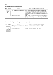
..., clean the transfer roller using a vacuum cleaner or by toner accumulated on the top edge or back of the drum and developing unit, and the fuser unit inlet. Defective transfer roller. Clean these areas and parts to remove toner. Print example Causes Defective polygon motor (laser scanner unit). Replace the control...
..., clean the transfer roller using a vacuum cleaner or by toner accumulated on the top edge or back of the drum and developing unit, and the fuser unit inlet. Defective transfer roller. Clean these areas and parts to remove toner. Print example Causes Defective polygon motor (laser scanner unit). Replace the control...

Service Manual
Page 137
... from paper is turned on , replace the power source PWB (See page 1-5-42). (14)When the trouble occurs in the paper feed/conveying section or fuser section is indicated when the main power switch is caught around registration sensor or exit sensor. Defective interlock switch on the high voltage PWB. Defective...
... from paper is turned on , replace the power source PWB (See page 1-5-42). (14)When the trouble occurs in the paper feed/conveying section or fuser section is indicated when the main power switch is caught around registration sensor or exit sensor. Defective interlock switch on the high voltage PWB. Defective...


