
Owners Manual
Page 1
P/NO : 38289U0323G (0602-REV00) Printed in Korea Record model number and serial number of the set . See the label attached on the back cover and quote this manual and operating your dealer when you require service. LCD TV PLASMA TV OWNER'S MANUAL LCD TV MODELS PLASMA TV MODELS 26LC2R* 32LC2R* 42PC1RV* 42PC3RV* Please read Information Manual included together before reading this information to your set . Retain it for future reference.
P/NO : 38289U0323G (0602-REV00) Printed in Korea Record model number and serial number of the set . See the label attached on the back cover and quote this manual and operating your dealer when you require service. LCD TV PLASMA TV OWNER'S MANUAL LCD TV MODELS PLASMA TV MODELS 26LC2R* 32LC2R* 42PC1RV* 42PC3RV* Please read Information Manual included together before reading this information to your set . Retain it for future reference.
Owners Manual
Page 3
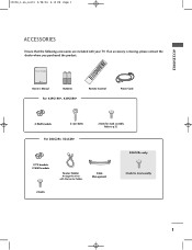
... Power Cord For 42PC1RV*, 42PC3RV* 2-Wall brackets 2-eye-bolts For 26LC2R*, 32LC2R* 2-bolts for stand assembly 2-bolts 1 Cable Management 32LC2R* only 4-bolts for stand assembly Refer to p.12 2-TV brackets 2-Wall brackets Twister Holder Arrange the wires with your TV. PIP PIP PR+ TV DVD SIZE VCR PIP POSTION INPUT MENU I/II OK SLEEP VOL...
... Power Cord For 42PC1RV*, 42PC3RV* 2-Wall brackets 2-eye-bolts For 26LC2R*, 32LC2R* 2-bolts for stand assembly 2-bolts 1 Cable Management 32LC2R* only 4-bolts for stand assembly Refer to p.12 2-TV brackets 2-Wall brackets Twister Holder Arrange the wires with your TV. PIP PIP PR+ TV DVD SIZE VCR PIP POSTION INPUT MENU I/II OK SLEEP VOL...
Owners Manual
Page 4
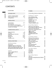
... Connection 18 VCR Setup 19-20 External Equipment Connections 21 DVD Setup 22-23 HDSTB Setup 24-25 PC Setup 26-27 Turning the TV On 28 SPECIAL FUNCTIONS PIP (Picture-In-Picture) Watching PIP 29 Programme Selection for Sub Picture 29 Input Source Selection for Sub Picture ...Language Selection 31 Switch on/off 31 SIMPLE Text 31 TOP Text 32 FASTEXT 32 Special Teletext Functions 33 2 TV MENU On Screen Menus Selection and Adjustment . . . . .34 Setting up TV stations Auto programme tuning 35 Manual programme tuning 36 Fine tuning 37 Assigning a station name 38 Programme edit 39...
... Connection 18 VCR Setup 19-20 External Equipment Connections 21 DVD Setup 22-23 HDSTB Setup 24-25 PC Setup 26-27 Turning the TV On 28 SPECIAL FUNCTIONS PIP (Picture-In-Picture) Watching PIP 29 Programme Selection for Sub Picture 29 Input Source Selection for Sub Picture ...Language Selection 31 Switch on/off 31 SIMPLE Text 31 TOP Text 32 FASTEXT 32 Special Teletext Functions 33 2 TV MENU On Screen Menus Selection and Adjustment . . . . .34 Setting up TV stations Auto programme tuning 35 Manual programme tuning 36 Fine tuning 37 Assigning a station name 38 Programme edit 39...

Owners Manual
Page 5
CONTENTS 0323G_1-en_rev01 2/28/06 4:12 PM Page 3 TV MENU Screen Menu Options Auto adjustment (RGB [PC] mode only 64 Manual Configure 65 Setting the Picture Format 66-67 Selecting Wide VGA/XGA mode 68 Initializing (Reset to original factory settings 69 APPENDIX Programming the Remote 70 Programming code 70-71 Troubleshooting Checklist 72-73 Maintenance 74 Product Specifications 75 External Control Device Setup 76 IR Codes 83 Remote control ir codes 84 3
CONTENTS 0323G_1-en_rev01 2/28/06 4:12 PM Page 3 TV MENU Screen Menu Options Auto adjustment (RGB [PC] mode only 64 Manual Configure 65 Setting the Picture Format 66-67 Selecting Wide VGA/XGA mode 68 Initializing (Reset to original factory settings 69 APPENDIX Programming the Remote 70 Programming code 70-71 Troubleshooting Checklist 72-73 Maintenance 74 Product Specifications 75 External Control Device Setup 76 IR Codes 83 Remote control ir codes 84 3
Owners Manual
Page 6
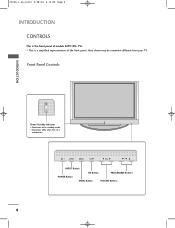
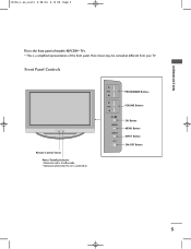
INPUT MENU OK VOL PR INPUT MENU OK VOL PR INPUT MENU OK VOL PR INPUT Button OK Button PROGRAMME Buttons POWER Button MENU Button VOLUME Buttons 4 Front Panel Controls INTRODUCTION Power/Standby Indicator • illuminates red in standby mode. • illuminates white when the set is switched on. I This is a simplified representation of models 42PC1RV* TVs. Here shown may be somewhat different from your TV. 0323G_1-en_rev01 2/28/06 4:12 PM Page 4 INTRODUCTION CONTROLS This is the front panel of the front panel.
INPUT MENU OK VOL PR INPUT MENU OK VOL PR INPUT MENU OK VOL PR INPUT Button OK Button PROGRAMME Buttons POWER Button MENU Button VOLUME Buttons 4 Front Panel Controls INTRODUCTION Power/Standby Indicator • illuminates red in standby mode. • illuminates white when the set is switched on. I This is a simplified representation of models 42PC1RV* TVs. Here shown may be somewhat different from your TV. 0323G_1-en_rev01 2/28/06 4:12 PM Page 4 INTRODUCTION CONTROLS This is the front panel of the front panel.
Owners Manual
Page 7
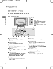
Front Panel Controls Remote Control Sensor Power/Standby Indicator • illuminates red in standby mode. • illuminates white when the set is a simplified representation of models 42PC3RV* TVs. PR PROGRAMME Buttons VOL VOLUME Buttons OK MENU INPUT OK Button MENU Button INPUT Button ON/OFF Button 5 I This is switched on. INTRODUCTION 0323G_1-en_rev01 2/28/06 4:12 PM Page 5 This is the front panel of the front panel. Here shown may be somewhat different from your TV.
Front Panel Controls Remote Control Sensor Power/Standby Indicator • illuminates red in standby mode. • illuminates white when the set is a simplified representation of models 42PC3RV* TVs. PR PROGRAMME Buttons VOL VOLUME Buttons OK MENU INPUT OK Button MENU Button INPUT Button ON/OFF Button 5 I This is switched on. INTRODUCTION 0323G_1-en_rev01 2/28/06 4:12 PM Page 5 This is the front panel of the front panel. Here shown may be somewhat different from your TV.
Owners Manual
Page 8
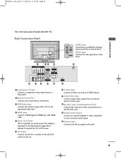
... 1 Component1/2 Input Connect a component video/audio device to the AV OUT socket on an AC power. Never attempt to operate the TV on DC power. 6 AV Output Connect second TV or monitor to these jacks. 9 RS-232C Input (CONTROL&SERVICE) Port Connect the serial port of models 42PC1RV*, 42PC3RV... Control Port Connect your surround sound system. 11 Antenna Input Connect over-the-air signals to HDMI port with HDMI cable. 5 Power Cord Socket This TV operates on the set. 7 S-Video Input Connect S-Video out from an S-VIDEO device. 8 Audio/Video Input Connect audio/video output from an external...
... 1 Component1/2 Input Connect a component video/audio device to the AV OUT socket on an AC power. Never attempt to operate the TV on DC power. 6 AV Output Connect second TV or monitor to these jacks. 9 RS-232C Input (CONTROL&SERVICE) Port Connect the serial port of models 42PC1RV*, 42PC3RV... Control Port Connect your surround sound system. 11 Antenna Input Connect over-the-air signals to HDMI port with HDMI cable. 5 Power Cord Socket This TV operates on the set. 7 S-Video Input Connect S-Video out from an S-VIDEO device. 8 Audio/Video Input Connect audio/video output from an external...
Owners Manual
Page 9
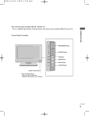
Front Panel Controls PR R Remote Control Sensor Power/Standby Indicator • illuminates red in standby mode. • illuminates white when the set is the front panel of the front panel. Here shown may be somewhat different from your TV. VOL OK MENU INPUT /I This is a simplified representation of models 26LC2R*, 32LC2R* TVs. INTRODUCTION 0323G_1-en_rev01 2/28/06 4:12 PM Page 7 This is switched on. I PROGRAMME Buttons VOLUME Buttons OK Button MENU Button INPUT Button ON/OFF Button 7
Front Panel Controls PR R Remote Control Sensor Power/Standby Indicator • illuminates red in standby mode. • illuminates white when the set is the front panel of the front panel. Here shown may be somewhat different from your TV. VOL OK MENU INPUT /I This is a simplified representation of models 26LC2R*, 32LC2R* TVs. INTRODUCTION 0323G_1-en_rev01 2/28/06 4:12 PM Page 7 This is switched on. I PROGRAMME Buttons VOLUME Buttons OK Button MENU Button INPUT Button ON/OFF Button 7
Owners Manual
Page 10
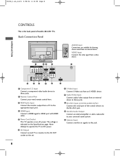
... HDMI Input Connect a HDMI signal to HDMI port with HDMI cable. 5 Power Cord Socket This TV operates on the Specifications page. Never attempt to operate the TV on DC power. 6 AV Output Connect second TV or monitor to the AV OUT socket on the set. 7 S-Video Input Connect S-Video out ...system. 11 Antenna Input Connect over-the-air signals to these jacks. 9 RS-232C Input (CONTROL&SERVICE) Port Connect the serial port of models 26LC2R* TVs. Back Connection Panel AV IN 1 VIDEO AUDIO L/MONO R AUDIO Input Connections are available for listening stereo sound from a video AC IN AV IN 2 ...
... HDMI Input Connect a HDMI signal to HDMI port with HDMI cable. 5 Power Cord Socket This TV operates on the Specifications page. Never attempt to operate the TV on DC power. 6 AV Output Connect second TV or monitor to the AV OUT socket on the set. 7 S-Video Input Connect S-Video out ...system. 11 Antenna Input Connect over-the-air signals to these jacks. 9 RS-232C Input (CONTROL&SERVICE) Port Connect the serial port of models 26LC2R* TVs. Back Connection Panel AV IN 1 VIDEO AUDIO L/MONO R AUDIO Input Connections are available for listening stereo sound from a video AC IN AV IN 2 ...
Owners Manual
Page 11
Never attempt to operate the TV on DC power. 6 AV Output Connect second TV or monitor to this jack. 9 Back Connection Panel AC IN AUDIO Input R Connections are available for listening AUDIO stereo sound from an external device to ... to the appropriate input port. 4 HDMI Input Connect a HDMI signal to these jacks. 9 RS-232C Input (CONTROL&SERVICE) Port Connect the serial port of models 32LC2R* TVs. 0323G_1-en_rev01 2/28/06 4:12 PM Page 9 INTRODUCTION This is indicated on the Specifications page. L/MONO VIDEO VIDEO Input Connects the video signal from a video...
Never attempt to operate the TV on DC power. 6 AV Output Connect second TV or monitor to this jack. 9 Back Connection Panel AC IN AUDIO Input R Connections are available for listening AUDIO stereo sound from an external device to ... to the appropriate input port. 4 HDMI Input Connect a HDMI signal to these jacks. 9 RS-232C Input (CONTROL&SERVICE) Port Connect the serial port of models 32LC2R* TVs. 0323G_1-en_rev01 2/28/06 4:12 PM Page 9 INTRODUCTION This is indicated on the Specifications page. L/MONO VIDEO VIDEO Input Connects the video signal from a video...

Owners Manual
Page 12
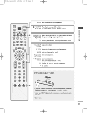
...10 INTRODUCTION INTRODUCTION REMOTE CONTROL KEY FUNCTIONS When using the remote control, aim it at the remote control sensor on -screen displays and returns to TV viewing from any mode. REVEAL INDEX ARC Selects your desired picture format. SLEEP Sets the sleep timer. 10 Press the D / E button ...and then OK button to the TV viewing from standby or off to the default settings brightness by changing mode source. adjustment It returns to standby. PIP Switches the sub picture PIP...
...10 INTRODUCTION INTRODUCTION REMOTE CONTROL KEY FUNCTIONS When using the remote control, aim it at the remote control sensor on -screen displays and returns to TV viewing from any mode. REVEAL INDEX ARC Selects your desired picture format. SLEEP Sets the sleep timer. 10 Press the D / E button ...and then OK button to the TV viewing from standby or off to the default settings brightness by changing mode source. adjustment It returns to standby. PIP Switches the sub picture PIP...
Owners Manual
Page 13
... 1 THUMBSTICK Allows you to the previously viewed programme. Don't mix old or used for teletext. with new ones. button Selects numbered items in a menu. INPUT TV POWER INPUT TV DVD 1 TELETEXT These buttons are used batteries with -).
... 1 THUMBSTICK Allows you to the previously viewed programme. Don't mix old or used for teletext. with new ones. button Selects numbered items in a menu. INPUT TV POWER INPUT TV DVD 1 TELETEXT These buttons are used batteries with -).

Owners Manual
Page 18
...Desktop Pedestal Installation For proper ventilation, allow a clearance of the set before installing the wall mounting bracket. 16 I The TV can be mounted horizontally. If grounding methods are available from the wall. Detailed installation instructions are not possible, have a ...inches Remove two screws of the backside of 4" on a desktop etc. 0323G_1-en_rev01 2/28/06 4:12 PM Page 16 INSTALLATION INSTALLATION I The TV is designed to telephone wires, lightening rods, or gas pipes. GROUNDING Ensure that you connect the earth ground wire to prevent possible electric shock.
...Desktop Pedestal Installation For proper ventilation, allow a clearance of the set before installing the wall mounting bracket. 16 I The TV can be mounted horizontally. If grounding methods are available from the wall. Detailed installation instructions are not possible, have a ...inches Remove two screws of the backside of 4" on a desktop etc. 0323G_1-en_rev01 2/28/06 4:12 PM Page 16 INSTALLATION INSTALLATION I The TV is designed to telephone wires, lightening rods, or gas pipes. GROUNDING Ensure that you connect the earth ground wire to prevent possible electric shock.

Owners Manual
Page 19
...product, which is to another place undo the ropes first. It will also prevent the product from the product. 42PC1RV*, 42PC3RV* 26LC2R*, 32LC2R* 1 1 2 2 1 Use the eye-bolts or TV brackets/bolts to fix the product to the wall so the product doesn't fall over when it is pulled in the upper holes.... (If your product has the bolts in the eye-bolts position before inserting the eye-bolts, loosen the bolts.) * Insert the eye-bolts or TV brackets/bolts and tighten them securely in the forward direction. It will prevent the product from falling for the size and weight of the product...
...product, which is to another place undo the ropes first. It will also prevent the product from the product. 42PC1RV*, 42PC3RV* 26LC2R*, 32LC2R* 1 1 2 2 1 Use the eye-bolts or TV brackets/bolts to fix the product to the wall so the product doesn't fall over when it is pulled in the upper holes.... (If your product has the bolts in the eye-bolts position before inserting the eye-bolts, loosen the bolts.) * Insert the eye-bolts or TV brackets/bolts and tighten them securely in the forward direction. It will prevent the product from falling for the size and weight of the product...
Owners Manual
Page 20
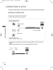
.... I For optimum picture quality, adjust antenna direction. Single-family Dwellings /Houses (Connect to wall jack for connection. I If signal needs to be split for two TVs, use an antenna signal splitter for outdoor antenna) I To prevent the equipment damage, never plug in any power cords until you have finished connecting all...
.... I For optimum picture quality, adjust antenna direction. Single-family Dwellings /Houses (Connect to wall jack for connection. I If signal needs to be split for two TVs, use an antenna signal splitter for outdoor antenna) I To prevent the equipment damage, never plug in any power cords until you have finished connecting all...

Owners Manual
Page 21
... socket of the screen may remain visible on the VCR and match the appropriate programme between the TV and VCR for viewing. I To avoid picture noise (interference), leave an adequate distance between TV and VCR. the fixed images on the sides of the VCR to the ANTENNA IN socket on...3 S-VIDEO VIDEO ( ) AUDIO 19 1 2 If the 4:3 picture format is used; When connecting with a RCA cable 1 Connect the AUDIO/VIDEO jacks between the VCR and TV. 0323G_1-en_rev01 2/28/06 4:12 PM Page 19 VCR SETUP I Typically a frozen still picture from the VCR to the AUDIO L/MONO jack of the set...
... socket of the screen may remain visible on the VCR and match the appropriate programme between the TV and VCR for viewing. I To avoid picture noise (interference), leave an adequate distance between TV and VCR. the fixed images on the sides of the VCR to the ANTENNA IN socket on...3 S-VIDEO VIDEO ( ) AUDIO 19 1 2 If the 4:3 picture format is used; When connecting with a RCA cable 1 Connect the AUDIO/VIDEO jacks between the VCR and TV. 0323G_1-en_rev01 2/28/06 4:12 PM Page 19 VCR SETUP I Typically a frozen still picture from the VCR to the AUDIO L/MONO jack of the set...

Owners Manual
Page 23
Match the jack colors (Video = yellow, Audio Left = white, and Audio Right = red) 2 Select AV2 input source with using the INPUT button on the remote control. (except 42PC3RV*) - If connected to external equipment operating guide. Video Game Set AV IN 2 R AUDIO L/MONO VIDEO 1 R AUDIO L VIDEO CONNECTIONS & SETUP 21 Camcorder 3 Operate the corresponding external equipment. Refer to AV IN1 input, select AV1input source. 0323G_1-en_rev01 2/28/06 4:12 PM Page 21 EXTERNAL EQUIPMENT CONNECTIONS 1 Connect the AUDIO/VIDEO jacks between TV and external equipment.
Match the jack colors (Video = yellow, Audio Left = white, and Audio Right = red) 2 Select AV2 input source with using the INPUT button on the remote control. (except 42PC3RV*) - If connected to external equipment operating guide. Video Game Set AV IN 2 R AUDIO L/MONO VIDEO 1 R AUDIO L VIDEO CONNECTIONS & SETUP 21 Camcorder 3 Operate the corresponding external equipment. Refer to AV IN1 input, select AV1input source. 0323G_1-en_rev01 2/28/06 4:12 PM Page 21 EXTERNAL EQUIPMENT CONNECTIONS 1 Connect the AUDIO/VIDEO jacks between TV and external equipment.

Owners Manual
Page 24
... connecting with using the INPUT button on the remote control. 5 Refer to the DVD player's manual for operating instructions. AV IN 1 Component ports on the TV Y PB PR S-VIDEO VIDEO ( ) AUDIO Y Pb Pr Video output ports Y COMPONENT IN B-Y R-Y VIDEO AUDIO on DVD player Y Cb Cr 1 Y PB PR 2 1 Connect the S-VIDEO output...
... connecting with using the INPUT button on the remote control. 5 Refer to the DVD player's manual for operating instructions. AV IN 1 Component ports on the TV Y PB PR S-VIDEO VIDEO ( ) AUDIO Y Pb Pr Video output ports Y COMPONENT IN B-Y R-Y VIDEO AUDIO on DVD player Y Cb Cr 1 Y PB PR 2 1 Connect the S-VIDEO output...

Owners Manual
Page 25
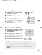
... OUT RS-232C IN (CONTROL&SERVICE) 1 DVD HDMI-DVD OUTPUT ! G If the DVD does not support Auto HDMI, you need to set to 1280x720p. NOTE G TV can receive the video and audio signal simultaneously with using a HDMI cable. AV IN 3 S-VIDEO VIDEO ( ) AUDIO CONNECTIONS & SETUP 23 COMPONENT IN 3 Refer to the...
... OUT RS-232C IN (CONTROL&SERVICE) 1 DVD HDMI-DVD OUTPUT ! G If the DVD does not support Auto HDMI, you need to set to 1280x720p. NOTE G TV can receive the video and audio signal simultaneously with using a HDMI cable. AV IN 3 S-VIDEO VIDEO ( ) AUDIO CONNECTIONS & SETUP 23 COMPONENT IN 3 Refer to the...
Owners Manual
Page 27
... set-top box to set the output resolution appropri- G If the digital set-top box does not support Auto HDMI, you need to 1280x720p. NOTE G TV can receive the video and audio signal simultaneously with using a HDMI cable. COMPONENT IN 3 Turn on the remote control. G If the digital set-top box...
... set-top box to set the output resolution appropri- G If the digital set-top box does not support Auto HDMI, you need to 1280x720p. NOTE G TV can receive the video and audio signal simultaneously with using a HDMI cable. COMPONENT IN 3 Turn on the remote control. G If the digital set-top box...


