
Owners Manual
Page 1
...power consumption that could exceed the limits necessary to your set . Record model number and serial number of the set . LCD TV OWNER'S MANUAL 32LG710H 37LG710H 42LG710H Installer Reference for Commercial Mode MPI/PPV Card Setup see page 19 Commercial Mode Setup see pages 88-114 Please read this... information to quality for Energy Star rating. 1-800-243-0000 USA, Consumer User 1-888-865-3026 USA, Commercial User 1-888-542-2623 CANADA LG Customer...
...power consumption that could exceed the limits necessary to your set . Record model number and serial number of the set . LCD TV OWNER'S MANUAL 32LG710H 37LG710H 42LG710H Installer Reference for Commercial Mode MPI/PPV Card Setup see page 19 Commercial Mode Setup see pages 88-114 Please read this... information to quality for Energy Star rating. 1-800-243-0000 USA, Consumer User 1-888-865-3026 USA, Commercial User 1-888-542-2623 CANADA LG Customer...
Owners Manual
Page 2
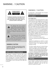
... to radio communications. The exclamation point within the product's enclosure that interference will not occur in a residential installation. NOTE TO CABLE/TV INSTALLER This reminder is intended to alert the user to correct the interference by one or more of the following two conditions: (1) This...system of the building, as practical. These limits are not expressly approved by turning the equipment off and on a circuit different from LG Electronics. This device complies with the instructions, may cause undesired operation (of the cable entry as close to Article 820-40 of...
... to radio communications. The exclamation point within the product's enclosure that interference will not occur in a residential installation. NOTE TO CABLE/TV INSTALLER This reminder is intended to alert the user to correct the interference by one or more of the following two conditions: (1) This...system of the building, as practical. These limits are not expressly approved by turning the equipment off and on a circuit different from LG Electronics. This device complies with the instructions, may cause undesired operation (of the cable entry as close to Article 820-40 of...
Owners Manual
Page 4
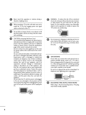
... a separate circuit breaker. that is, a single outlet circuit which powers only that appliances be placed upon . Periodically examine the cord of the TV. 13 Do not allow an impact shock or any objects to fall into the product, and do not place objects filled with an exact replacement... insulation are not possible, have the cord replaced with liquids, such as being twisted, kinked, pinched, closed in fire or electric shock. a TV with something. 14 CAUTION concerning the Power Cord : It is the disconnecting device. Do not install this product near flammable objects such as this ...
... a separate circuit breaker. that is, a single outlet circuit which powers only that appliances be placed upon . Periodically examine the cord of the TV. 13 Do not allow an impact shock or any objects to fall into the product, and do not place objects filled with an exact replacement... insulation are not possible, have the cord replaced with liquids, such as being twisted, kinked, pinched, closed in fire or electric shock. a TV with something. 14 CAUTION concerning the Power Cord : It is the disconnecting device. Do not install this product near flammable objects such as this ...
Owners Manual
Page 5
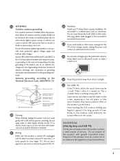
... Code Antenna Lead in . Do not clean with a soft cloth to an antenna discharge unit, size of grounding conductors, location of the TV. 22 Ventilation Install your TV where there is turned off, unplugged and all cables have no adverse effect on the screen. Do not install in excessively dusty places...However, they have been removed. Section 810 of time. Do not press against or put stress on it. 25 Keep the product away from the TV or hear strange sounds, unplug the power cord contact an authorized service center. 24 Do not press strongly upon the panel with cloth or other...
... Code Antenna Lead in . Do not clean with a soft cloth to an antenna discharge unit, size of grounding conductors, location of the TV. 22 Ventilation Install your TV where there is turned off, unplugged and all cables have no adverse effect on the screen. Do not install in excessively dusty places...However, they have been removed. Section 810 of time. Do not press against or put stress on it. 25 Keep the product away from the TV or hear strange sounds, unplug the power cord contact an authorized service center. 24 Do not press strongly upon the panel with cloth or other...

Owners Manual
Page 6
...Picture 50 Picture Size (Aspect Ratio) Control 52 Preset Picture Settings - CONTENTS WARNING / CAUTION 2 SAFETY INSTRUCTIONS 3 FEATURES OF THIS TV 8 PREPARATION Accessories 9 Front Panel Information 10 Back Panel Information 11 Stand Instruction 12 Cable Management 13 Desktop Pedestal Installation 14 Swivel Stand ...User Mode 63 - Caption Option 74 Digital Broadcasting System Captions 73 - SRS TruSurround XT 64 Clear Voice ll 65 Balance 66 TV Speakers On/Off Setup 67 Audio Reset 68 Stereo/SAP Broadcast Setup 69 Audio Language 70 On-Screen Menus Language Selection 71 ...
...Picture 50 Picture Size (Aspect Ratio) Control 52 Preset Picture Settings - CONTENTS WARNING / CAUTION 2 SAFETY INSTRUCTIONS 3 FEATURES OF THIS TV 8 PREPARATION Accessories 9 Front Panel Information 10 Back Panel Information 11 Stand Instruction 12 Cable Management 13 Desktop Pedestal Installation 14 Swivel Stand ...User Mode 63 - Caption Option 74 Digital Broadcasting System Captions 73 - SRS TruSurround XT 64 Clear Voice ll 65 Balance 66 TV Speakers On/Off Setup 67 Audio Reset 68 Stereo/SAP Broadcast Setup 69 Audio Language 70 On-Screen Menus Language Selection 71 ...
Owners Manual
Page 7
.... 95 LT2002 Cloning Learning Setup 96 Cloning Connections/Teaching Setup 97 Installer Menu 98 Reference: Detailed Instructions For Making A Master TV 104 Reference: Procedures for adding Channel Label Icons/Custom Channel Labels (2-5-4 + MENU Mode) 105 Reference: Clonable Menu Features 106 Reference:...FTG Card Operation Setup 110 FTG Card Channel Map Overview 111 FTG Installer Menu Overview 112 FTG Operation Troubleshooting 113 TV Aux Input Configuration 113 B-LAN Setup and Overview 114 APPENDIX Troubleshooting 115 Reference: LT2002 Cloning Procedure Troubleshooting 117 Troubleshooting...
.... 95 LT2002 Cloning Learning Setup 96 Cloning Connections/Teaching Setup 97 Installer Menu 98 Reference: Detailed Instructions For Making A Master TV 104 Reference: Procedures for adding Channel Label Icons/Custom Channel Labels (2-5-4 + MENU Mode) 105 Reference: Clonable Menu Features 106 Reference:...FTG Card Operation Setup 110 FTG Card Channel Map Overview 111 FTG Installer Menu Overview 112 FTG Operation Troubleshooting 113 TV Aux Input Configuration 113 B-LAN Setup and Overview 114 APPENDIX Troubleshooting 115 Reference: LT2002 Cloning Procedure Troubleshooting 117 Troubleshooting...
Owners Manual
Page 8
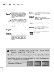
...keep dialogue audible when background noise swells. Using a sophisticated algorithm, the LG processes picture quality elements including brightness, contrast, color, sharpness and white balance. The result is displayed on the TV for an extended period. 8 HDMI, the HDMI logo and High-... and 720p resolutions. I In order to prevent image burn, avoid displaying a fixed image on the letterboxed areas of HDMI Licensing LLC." LG TV include a unique invisible speaker system, tuned by increasing the "sweet spot", giving a wider and richer sound field. TruSurround XT technology is...
...keep dialogue audible when background noise swells. Using a sophisticated algorithm, the LG processes picture quality elements including brightness, contrast, color, sharpness and white balance. The result is displayed on the TV for an extended period. 8 HDMI, the HDMI logo and High-... and 720p resolutions. I In order to prevent image burn, avoid displaying a fixed image on the letterboxed areas of HDMI Licensing LLC." LG TV include a unique invisible speaker system, tuned by increasing the "sweet spot", giving a wider and richer sound field. TruSurround XT technology is...
Owners Manual
Page 9
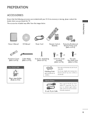
TV GUIDESTB POWER PORTAL DVD INFOVCR i RETURN MENU 1 .:/, 4 GHI VOL ALPHA/NUCMC REMOMVEUTE 2 CH GAP E ABC 7 5 3 PQRS JKL DEF 8 6 TUV MNO 0 9 &@ WXYZ PIP PIP CH- The ... use shielded signal interface cables with ferrite cores to P.13) Polishing Cloth (Not included with all models.) * Wipe spots on the exterior only with your TV. PREPARATION PREPERATION ACCESSORIES Ensure that the following accessories are included with the polishing cloth. * Do not wipe roughly when removing stains. If an accessory is...
TV GUIDESTB POWER PORTAL DVD INFOVCR i RETURN MENU 1 .:/, 4 GHI VOL ALPHA/NUCMC REMOMVEUTE 2 CH GAP E ABC 7 5 3 PQRS JKL DEF 8 6 TUV MNO 0 9 &@ WXYZ PIP PIP CH- The ... use shielded signal interface cables with ferrite cores to P.13) Polishing Cloth (Not included with all models.) * Wipe spots on the exterior only with your TV. PREPARATION PREPERATION ACCESSORIES Ensure that the following accessories are included with the polishing cloth. * Do not wipe roughly when removing stains. If an accessory is...
Owners Manual
Page 10
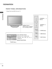
CHANNEL( , ) CH Buttons Intelligent Sensor Adjusts picture according to the surrounding conditions. VOL ENTER Power/Standby Indicator Illuminates red in standby mode. Illuminates blue when the set is switched on. PREPARATION PREPARATION FRONT PANEL INFORMATION I Image shown may differ from your TV. Remote Control Sensor POWER Button MENU INPUT VOLUME (+, -) Buttons ENTER Button MENU Button INPUT Button 10
CHANNEL( , ) CH Buttons Intelligent Sensor Adjusts picture according to the surrounding conditions. VOL ENTER Power/Standby Indicator Illuminates red in standby mode. Illuminates blue when the set is switched on. PREPARATION PREPARATION FRONT PANEL INFORMATION I Image shown may differ from your TV. Remote Control Sensor POWER Button MENU INPUT VOLUME (+, -) Buttons ENTER Button MENU Button INPUT Button 10
Owners Manual
Page 11
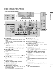
...analog PC audio input. 3 LAN (SERVICE ONLY) For connecting to a control network. 4 RESET Performs a hardware reset. I Image shown may differ from your TV. R 12 COMPONENT IN Analog Connection. Accepts DVI video using an adapter or HDMI to receive over-the-air (OTA) signals. 15 M.P. R BACK PANEL INFORMATION...cable for video & a red and white cable for viewing multimedia files. 11 home theater systems. Note: In standby mode, this to an LG remote jack pack system. 14 ANTENNA IN Connect an antenna to DVI cable (not included) 9 SPEAKER OUT 8Ω For use with external ...
...analog PC audio input. 3 LAN (SERVICE ONLY) For connecting to a control network. 4 RESET Performs a hardware reset. I Image shown may differ from your TV. R 12 COMPONENT IN Analog Connection. Accepts DVI video using an adapter or HDMI to receive over-the-air (OTA) signals. 15 M.P. R BACK PANEL INFORMATION...cable for video & a red and white cable for viewing multimedia files. 11 home theater systems. Note: In standby mode, this to an LG remote jack pack system. 14 ANTENNA IN Connect an antenna to DVI cable (not included) 9 SPEAKER OUT 8Ω For use with external ...
Owners Manual
Page 12
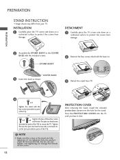
... -tightening can damage the threads on a cushioned surface to the COVER BASE with the included screws. COVER BASE 3 Insert the stand as parts of the TV). But do not over tighten, over the hole for the stand. or x 2 x 2 Tighten the two of these four screws and the two Torx ...head screws with the four screws (provided as shown. 3 Detach the stand from damage. 2 Assemble the STAND BODY to protect the screen from your TV. PREPARATION PREPARATION STAND INSTRUCTION I Image shown may differ from damage. Tighten the two Torx plus star head screws (provided as parts of the...
... -tightening can damage the threads on a cushioned surface to the COVER BASE with the included screws. COVER BASE 3 Insert the stand as parts of the TV). But do not over tighten, over the hole for the stand. or x 2 x 2 Tighten the two of these four screws and the two Torx ...head screws with the four screws (provided as shown. 3 Detach the stand from damage. 2 Assemble the STAND BODY to protect the screen from your TV. PREPARATION PREPARATION STAND INSTRUCTION I Image shown may differ from damage. Tighten the two Torx plus star head screws (provided as parts of the...
Owners Manual
Page 13
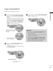
...MANAGEMENT CLIP as needed after reading the section titled EXTERNAL EQUIPMENT SETUP. NOTE G Do not hold the CABLE MANAGEMENT CLIP when moving the TV. - CABLE MANAGEMENT CLIP CABLE HOLDER 13 PROTECTIVE BRACKET/Screw (This feature is dropped, you may be injured or the product may ...differ from being removed by accident, secure the power cable with your TV. 1 Connect the cables as shown. If a CABLE HOLDER was included with the included PROTECTIVE BRACKET /Screw. PREPARATION CABLE MANAGEMENT I Image shown...
...MANAGEMENT CLIP as needed after reading the section titled EXTERNAL EQUIPMENT SETUP. NOTE G Do not hold the CABLE MANAGEMENT CLIP when moving the TV. - CABLE MANAGEMENT CLIP CABLE HOLDER 13 PROTECTIVE BRACKET/Screw (This feature is dropped, you may be injured or the product may ...differ from being removed by accident, secure the power cable with your TV. 1 Connect the cables as shown. If a CABLE HOLDER was included with the included PROTECTIVE BRACKET /Screw. PREPARATION CABLE MANAGEMENT I Image shown...
Owners Manual
Page 14
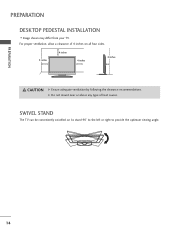
SWIVEL STAND The TV can be conveniently swivelled on all four sides. 4 inches 4 inches 4 inches 4 inches CAUTION G Ensure adequate ventilation by following the clearance recommendations. For proper ventilation, allow a clearance of heat source. G Do not mount near or above any type of 4 inches on its stand 90° to the left or right to provide the optimum viewing angle. 14 PREPARATION PREPARATION DESKTOP PEDESTAL INSTALLATION I Image shown may differ from your TV.
SWIVEL STAND The TV can be conveniently swivelled on all four sides. 4 inches 4 inches 4 inches 4 inches CAUTION G Ensure adequate ventilation by following the clearance recommendations. For proper ventilation, allow a clearance of heat source. G Do not mount near or above any type of 4 inches on its stand 90° to the left or right to provide the optimum viewing angle. 14 PREPARATION PREPARATION DESKTOP PEDESTAL INSTALLATION I Image shown may differ from your TV.
Owners Manual
Page 15
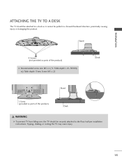
Tipping, shaking, or rocking the TV may cause injury. 15 PREPARATION ATTACHING THE TV TO A DESK The TV should be pulled in a forward/backward direction, potentially causing injury or damaging the product. Stand 4-Screws (not provided as parts of the product) Desk G Recommended screw size: M5 x L (*L: Table depth + 8~10 mm) ex) Table depth: 15mm, Screw: M5 x 25 Stand 1-Screw (provided as parts of the product) Desk WARNING G To prevent TV from falling over, the TV should be attached to a desk so it cannot be securely attached to the floor/wall per installation instructions.
Tipping, shaking, or rocking the TV may cause injury. 15 PREPARATION ATTACHING THE TV TO A DESK The TV should be pulled in a forward/backward direction, potentially causing injury or damaging the product. Stand 4-Screws (not provided as parts of the product) Desk G Recommended screw size: M5 x L (*L: Table depth + 8~10 mm) ex) Table depth: 15mm, Screw: M5 x 25 Stand 1-Screw (provided as parts of the product) Desk WARNING G To prevent TV from falling over, the TV should be attached to a desk so it cannot be securely attached to the floor/wall per installation instructions.
Owners Manual
Page 16
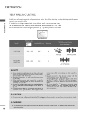
... standard dimension, as they may damage the TV or allow the TV to a fall and result in personal injury due to a wall. A B PREPARATION Model VESA (A * B) A Standard Screw Quantity B Wall Mounting Bracket (sold separately) 32LG710H 200 * 100 M4 4 RW230 AW-47LG30M 37LG710H, 42LG710H 200 * 200 M6 4 AW-... ceiling or slanted wall, it may result in severe personal injury. G Do not use an LG brand wall mount when mounting the TV to electric shock. G LG is not liable for TV damage or personal injury when a non-VESA or non specified wall mount is not liable for...
... standard dimension, as they may damage the TV or allow the TV to a fall and result in personal injury due to a wall. A B PREPARATION Model VESA (A * B) A Standard Screw Quantity B Wall Mounting Bracket (sold separately) 32LG710H 200 * 100 M4 4 RW230 AW-47LG30M 37LG710H, 42LG710H 200 * 200 M6 4 AW-... ceiling or slanted wall, it may result in severe personal injury. G Do not use an LG brand wall mount when mounting the TV to electric shock. G LG is not liable for TV damage or personal injury when a non-VESA or non specified wall mount is not liable for...
Owners Manual
Page 17
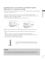
...the eye-bolts position before inserting the eye-bolts, loosen the bolts. * Insert the eye-bolts or TV brackets/bolts and tighten them securely in the upper holes. NOTE G Use a platform or cabinet strong ...weight of the bracket on the wall and the one on or hang from the TV. G To use the TV safely make sure that the TV be pulled in a forward direction, potentially causing injury or damaging the product. We... not using a wall mount). Match the height of the bracket that you set up the TV close to tie the rope so it cannot be attached to a wall so it becomes horizontal between the wall ...
...the eye-bolts position before inserting the eye-bolts, loosen the bolts. * Insert the eye-bolts or TV brackets/bolts and tighten them securely in the upper holes. NOTE G Use a platform or cabinet strong ...weight of the bracket on the wall and the one on or hang from the TV. G To use the TV safely make sure that the TV be pulled in a forward direction, potentially causing injury or damaging the product. We... not using a wall mount). Match the height of the bracket that you set up the TV close to tie the rope so it cannot be attached to a wall so it becomes horizontal between the wall ...
Owners Manual
Page 18
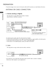
... OR CABLE CONNECTION 1. I If the antenna needs to be split for outdoor antenna) Copper Wire Be careful not to wall jack for two TV's, install a 2-Way Signal Splitter. Cable TV Wall Jack RF Coaxial Wire (75 ohm) ANTENNA IN M.P.I To prevent damage, do not connect to using a Wall Antenna Socket or Outdoor...
... OR CABLE CONNECTION 1. I If the antenna needs to be split for outdoor antenna) Copper Wire Be careful not to wall jack for two TV's, install a 2-Way Signal Splitter. Cable TV Wall Jack RF Coaxial Wire (75 ohm) ANTENNA IN M.P.I To prevent damage, do not connect to using a Wall Antenna Socket or Outdoor...
Owners Manual
Page 20
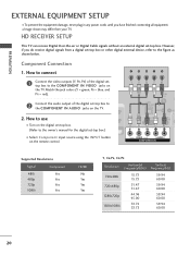
... EQUIPMENT SETUP I To prevent the equipment damage, never plug in any power cords until you do receive digital signals from your TV. HD RECEIVER SETUP This TV can receive Digital Over-the-air or Digital Cable signals without an external digital set -top box.) I Image shown may differ...output of the digital settop box to the owner's manual for the digital set -top box. However, if you have finished connecting all equipment. TV-LINK CFG C 1 LAN (SERVICE ONLY) 2 RESET UPD RGB(PC) RS (SER AUDIO (RGB/DVI) RGB IN VIDEO AAUUDDIIOO CCOOMMPPOONNEENNTTININ Supported ...
... EQUIPMENT SETUP I To prevent the equipment damage, never plug in any power cords until you do receive digital signals from your TV. HD RECEIVER SETUP This TV can receive Digital Over-the-air or Digital Cable signals without an external digital set -top box.) I Image shown may differ...output of the digital settop box to the owner's manual for the digital set -top box. However, if you have finished connecting all equipment. TV-LINK CFG C 1 LAN (SERVICE ONLY) 2 RESET UPD RGB(PC) RS (SER AUDIO (RGB/DVI) RGB IN VIDEO AAUUDDIIOO CCOOMMPPOONNEENNTTININ Supported ...
Owners Manual
Page 21
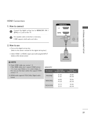
... control. ! In this case use 1 I Turn on the digital set -top box.) I Select HDMI1 or HDMI2 input source with using the INPUT button on the TV. RJP INTERFACE VID 2. How to use the latest cables that support HDMI version 1.3. If the HDMI cables don't support HDMI version 1.3, it can cause flickers...
... control. ! In this case use 1 I Turn on the digital set -top box.) I Select HDMI1 or HDMI2 input source with using the INPUT button on the TV. RJP INTERFACE VID 2. How to use the latest cables that support HDMI version 1.3. If the HDMI cables don't support HDMI version 1.3, it can cause flickers...

Owners Manual
Page 22
... jack on the remote control. NOTE G A DVI to the owner's manual for this connection. DVI-DTV OUTPUT LL R 22 HDMI/DVI IN 2 1(DVI) RJP INTERFACE 1 TV-LINK CFG G CO LAN (SERVICE ONLY) RESET RGB(PC) UPDA R (S AUDIO (RGB/DVI) RGB IN VIDEO AUDIO COMPONENT IN 2 ! DVI doesn't support audio, so ...a separate audio connection is required for the digital set-top box.) I Select the HDMI1 input source on the TV using the INPUT button on the TV. 2. How to connect 1 Connect the DVI output of the digital set-top box to the HDMI/DVI IN 1 (DVI) jack ...
... jack on the remote control. NOTE G A DVI to the owner's manual for this connection. DVI-DTV OUTPUT LL R 22 HDMI/DVI IN 2 1(DVI) RJP INTERFACE 1 TV-LINK CFG G CO LAN (SERVICE ONLY) RESET RGB(PC) UPDA R (S AUDIO (RGB/DVI) RGB IN VIDEO AUDIO COMPONENT IN 2 ! DVI doesn't support audio, so ...a separate audio connection is required for the digital set-top box.) I Select the HDMI1 input source on the TV using the INPUT button on the TV. 2. How to connect 1 Connect the DVI output of the digital set-top box to the HDMI/DVI IN 1 (DVI) jack ...


