

Owners Manual
Page 1
S. Retain it for energy efficiency. A.,Inc. P/NO : 38289U0527F (0707-REV08) Printed in Korea LCD TV MODELS: 32LC2D 32LC2DU 37LC2D 42LC2D PLASMA TV MODELS: 42PC3D 42PC3DC 42PC3DV 50PC3D 60PC1D 60PC1DC OWNER'S MANUAL Internet Home Page : http://www.lge.com http://www.lg.ca http://www.lgcommercial.com ENERGYSTAR is a set of the set . Record model number and...
S. Retain it for energy efficiency. A.,Inc. P/NO : 38289U0527F (0707-REV08) Printed in Korea LCD TV MODELS: 32LC2D 32LC2DU 37LC2D 42LC2D PLASMA TV MODELS: 42PC3D 42PC3DC 42PC3DV 50PC3D 60PC1D 60PC1DC OWNER'S MANUAL Internet Home Page : http://www.lge.com http://www.lg.ca http://www.lgcommercial.com ENERGYSTAR is a set of the set . Record model number and...
Owners Manual
Page 2
...modification could void the user's authority to correct the interference by turning the equipment off and on a circuit different from LG Electronics Corporation. REFER TO QUALIFIED SERVICE PERSONNEL. REGULATORY INFORMATION This equipment has been tested and found to comply with the instructions... sufficient magnitude to constitute a risk of important operating and maintenance (servicing) instructions in a residential installation. NOTE TO CABLE/TV INSTALLER: This reminder is intended to alert the user to operate this product in any way without written authorization from that ...
...modification could void the user's authority to correct the interference by turning the equipment off and on a circuit different from LG Electronics Corporation. REFER TO QUALIFIED SERVICE PERSONNEL. REGULATORY INFORMATION This equipment has been tested and found to comply with the instructions... sufficient magnitude to constitute a risk of important operating and maintenance (servicing) instructions in a residential installation. NOTE TO CABLE/TV INSTALLER: This reminder is intended to alert the user to operate this product in any way without written authorization from that ...

Owners Manual
Page 4
.... 4 CAUTION concerning the Power Cord Most appliances recommend they have the cord replaced with an exact replacement part by the manufacturer, or sold with TV. - On Disposal a. The fluorescent lamp used , use of mercury. Do not dispose of this product contains a small amount of the appliance,...fire. b. Refer all servicing to plugs, wall outlets, and the point where the cord exits the appliance. Any of time. FOR LCD TV Note - DISCONNECTING DEVICE FROM MAINS Main plug is damaged, liquid has been spilled or objects have fallen into the apparatus, the apparatus has ...
.... 4 CAUTION concerning the Power Cord Most appliances recommend they have the cord replaced with an exact replacement part by the manufacturer, or sold with TV. - On Disposal a. The fluorescent lamp used , use of mercury. Do not dispose of this product contains a small amount of the appliance,...fire. b. Refer all servicing to plugs, wall outlets, and the point where the cord exits the appliance. Any of time. FOR LCD TV Note - DISCONNECTING DEVICE FROM MAINS Main plug is damaged, liquid has been spilled or objects have fallen into the apparatus, the apparatus has ...

Owners Manual
Page 5
... Audio Menu Options 14 15 16~17 18 19~20 20 21~22 23~24 25 25 26~28 Attaching the TV to a wall Desktop Pedestal Installation Basic Connection Antenna or Cable Connection VCR Setup External AV Source Setup DVD Setup HDSTB... 31 31 32 33 33 34 35 35~36 37 38 39 40 41 41~42 43 43 Turning on the TV Volume Adjustment Channel Selection On Screen Menus Language Selection On Screen Menus Selection and Adjustment EZ Scan (Channel Search) Manual...Level Video Reset Audio Language Auto Sound Control(EZ Sound) Manual Sound Control (EZ Sound-User option) Balance TV Speakers On/Off Setup Operation Contents 5
... Audio Menu Options 14 15 16~17 18 19~20 20 21~22 23~24 25 25 26~28 Attaching the TV to a wall Desktop Pedestal Installation Basic Connection Antenna or Cable Connection VCR Setup External AV Source Setup DVD Setup HDSTB... 31 31 32 33 33 34 35 35~36 37 38 39 40 41 41~42 43 43 Turning on the TV Volume Adjustment Channel Selection On Screen Menus Language Selection On Screen Menus Selection and Adjustment EZ Scan (Channel Search) Manual...Level Video Reset Audio Language Auto Sound Control(EZ Sound) Manual Sound Control (EZ Sound-User option) Balance TV Speakers On/Off Setup Operation Contents 5
Owners Manual
Page 7
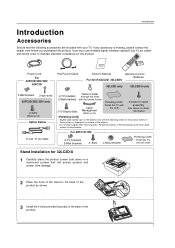
...to maintain standard compliance for 32LC2D/U 1 Carefully place the product screen side down on surface of the product. 7 For 60PC1D/1DC 2-TV brackets 2-Wall brackets 4- User must use shielded signal interface cables(D-sub 15 pin cable) with the cleansing cloths for the product exterior ...shown. 3 Install the 4 bolts provided securely, in the back of the exterior. Power Cord 75Ω Round Cable Owner's Manual TV INPUT TV AUDIO POWER DAY - Do not wipe roughly when removing stain. Stand Installation for the product. Please be cautious of that the following ...
...to maintain standard compliance for 32LC2D/U 1 Carefully place the product screen side down on surface of the product. 7 For 60PC1D/1DC 2-TV brackets 2-Wall brackets 4- User must use shielded signal interface cables(D-sub 15 pin cable) with the cleansing cloths for the product exterior ...shown. 3 Install the 4 bolts provided securely, in the back of the exterior. Power Cord 75Ω Round Cable Owner's Manual TV INPUT TV AUDIO POWER DAY - Do not wipe roughly when removing stain. Stand Installation for the product. Please be cautious of that the following ...
Owners Manual
Page 8
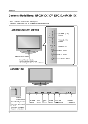
... on . 8 ENTER ENTER POWER INPUT Button Button MENU ENTER Button Button VOLUME (F,G)Buttons CHANNEL (E,D)Buttons This picture shown below may be somewhat different from your TV. 42PC3D/3DC/3DV, 50PC3D Remote Control Sensor Power/Standby Indicator • illuminates red in standby mode. CH VOL ENTER MENU INPUT CHANNEL (D, E) Buttons VOLUME (F,G) Buttons...
... on . 8 ENTER ENTER POWER INPUT Button Button MENU ENTER Button Button VOLUME (F,G)Buttons CHANNEL (E,D)Buttons This picture shown below may be somewhat different from your TV. 42PC3D/3DC/3DV, 50PC3D Remote Control Sensor Power/Standby Indicator • illuminates red in standby mode. CH VOL ENTER MENU INPUT CHANNEL (D, E) Buttons VOLUME (F,G) Buttons...
Owners Manual
Page 9
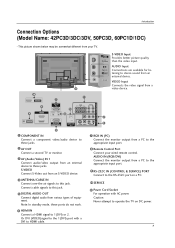
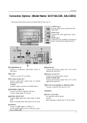
.../audio device to these jacks. 7 RGB IN (PC) Connect the monitor output from a PC to the appropriate input port. 2 AV OUT Connect a second TV or monitor. 3 AV (Audio/Video) IN 1 Connect audio/video output from an S-VIDEO device. 4 ANTENNA/CABLE IN Connect over-the air signals to these... ports do notVwIDEOork. 8 Remote Control Port Connect your TV. S-VIDEO Connect S-Video out from an external device to this jack. 5 DIGITAL AUDIO OUT Connect digital audio from a 11 video device. R AUDIO ...
.../audio device to these jacks. 7 RGB IN (PC) Connect the monitor output from a PC to the appropriate input port. 2 AV OUT Connect a second TV or monitor. 3 AV (Audio/Video) IN 1 Connect audio/video output from an S-VIDEO device. 4 ANTENNA/CABLE IN Connect over-the air signals to these... ports do notVwIDEOork. 8 Remote Control Port Connect your TV. S-VIDEO Connect S-Video out from an external device to this jack. 5 DIGITAL AUDIO OUT Connect digital audio from a 11 video device. R AUDIO ...
Owners Manual
Page 10
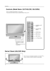
... Name: 32/37/42LC2D, 32LC2DU) - This is switched on its stand 30° to the left or right to provide the optimum viewing angle. The TV can be somewhat different from your TV. CHANNEL (D, E) Buttons VOLUME (F,G) Buttons ENTER Button MENU Button INPUT Button (Power) Button Swivel Stand (42LC2D Only) - R 10
... Name: 32/37/42LC2D, 32LC2DU) - This is switched on its stand 30° to the left or right to provide the optimum viewing angle. The TV can be somewhat different from your TV. CHANNEL (D, E) Buttons VOLUME (F,G) Buttons ENTER Button MENU Button INPUT Button (Power) Button Swivel Stand (42LC2D Only) - R 10
Owners Manual
Page 11
...PC to the appropriate input port. 9 RS-232C IN (CONTROL & SERVICE) PORT Connect to HDMI cable. 11 Caution: Never attempt to operate the TV on a PC. 10 SERVICE 11 Power Cord Socket For operation with AC power. AUDIO Input Connections are available for listening to AC IN stereo sound...) DIGITAL AUDIO OUT S-VIDEO VIDEO (MONO) AUDIO 3 AV OUT 1 COMPONENT IN Connect a component these ports do not work. 8 Remote Control Port Connect your TV. S-VIDEO Connect S-Video out from an S-VIDEO device. 4 ANTENNA/CABLE IN Connect over-the air signals to this jack. This picture shown below may be...
...PC to the appropriate input port. 9 RS-232C IN (CONTROL & SERVICE) PORT Connect to HDMI cable. 11 Caution: Never attempt to operate the TV on a PC. 10 SERVICE 11 Power Cord Socket For operation with AC power. AUDIO Input Connections are available for listening to AC IN stereo sound...) DIGITAL AUDIO OUT S-VIDEO VIDEO (MONO) AUDIO 3 AV OUT 1 COMPONENT IN Connect a component these ports do not work. 8 Remote Control Port Connect your TV. S-VIDEO Connect S-Video out from an S-VIDEO device. 4 ANTENNA/CABLE IN Connect over-the air signals to this jack. This picture shown below may be...
Owners Manual
Page 12
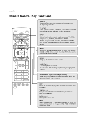
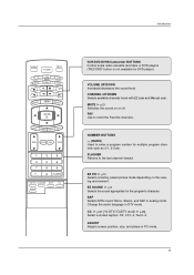
...) Allows you select the amount of the screen. INPUT External input modes rotate in Component 1-2, RGB, HDMI1/DVI and HDMI2 mode. 12 TV INPUT In AV1-2, Component 1-2, or RGB-PC, HDMI1/DVI, and HDMI2 input sources, screen returns to the default settings brightness by changing ... MUTE FAV CH 1 2 3 4 5 6 7 8 9 0 FLASHBK EZ PIC EZ SOUND SAP CC ADJUST POWER Turns your preference. Not available in regular sequence: TV, AV1-2, Component 1-2, RGB-PC, HDMI1/DVI or HDMI2. (AV 1-2, Component 1-2, RGB-PC , HDMI1/DVI or HDMI2 input sources are linked automatically, only if these ...
...) Allows you select the amount of the screen. INPUT External input modes rotate in Component 1-2, RGB, HDMI1/DVI and HDMI2 mode. 12 TV INPUT In AV1-2, Component 1-2, or RGB-PC, HDMI1/DVI, and HDMI2 input sources, screen returns to the default settings brightness by changing ... MUTE FAV CH 1 2 3 4 5 6 7 8 9 0 FLASHBK EZ PIC EZ SOUND SAP CC ADJUST POWER Turns your preference. Not available in regular sequence: TV, AV1-2, Component 1-2, RGB-PC, HDMI1/DVI or HDMI2. (AV 1-2, Component 1-2, RGB-PC , HDMI1/DVI or HDMI2 input sources are linked automatically, only if these ...
Owners Manual
Page 13
... - (DASH) Used to enter a program number for multiple program channels such as 2-1, 2-2,etc. ADJUST Adjusts screen position, size, and phase in PC mode. 13 Introduction TV INPUT POWER TV AUDIO DVD MODE CABLE INPUT VCR STB BRIGHT -
... - (DASH) Used to enter a program number for multiple program channels such as 2-1, 2-2,etc. ADJUST Adjusts screen position, size, and phase in PC mode. 13 Introduction TV INPUT POWER TV AUDIO DVD MODE CABLE INPUT VCR STB BRIGHT -
Owners Manual
Page 14
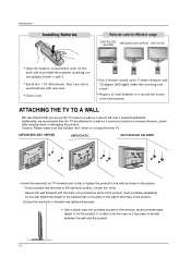
... holes in a recycle bin to a wall so it cannot fall over if pushed backwards. MENU BRIGHT + ENTER EXIT TIMER RATIO INFO TV INPUT POWER TV AUDIO DVD MODE CABLE INPUT VCR STB BRIGHT - Caution: Please make sure that is safer to tie the rope so it cannot be ... picture. * If your product has the bolts in a forward direction, potentially causing injury or damaging the product. I Use a remote control up the TV close to preserve environment. MENU BRIGHT + ENTER EXIT TIMER RATIO INFO I Dispose of the bracket that children don't climb on the wall. Introduction Installing...
... holes in a recycle bin to a wall so it cannot fall over if pushed backwards. MENU BRIGHT + ENTER EXIT TIMER RATIO INFO TV INPUT POWER TV AUDIO DVD MODE CABLE INPUT VCR STB BRIGHT - Caution: Please make sure that is safer to tie the rope so it cannot be ... picture. * If your product has the bolts in a forward direction, potentially causing injury or damaging the product. I Use a remote control up the TV close to preserve environment. MENU BRIGHT + ENTER EXIT TIMER RATIO INFO I Dispose of the bracket that children don't climb on the wall. Introduction Installing...

Owners Manual
Page 15
Installation Installation DESKTOP PEDESTAL INSTALLATION For proper ventilation, allow a clearance of 4inches on each side from your TV. Do not try to ground the unit by following the clearance recommendations. If grounding methods are not possible, have a qualified electrician install a separate circuit breaker. I ...
Installation Installation DESKTOP PEDESTAL INSTALLATION For proper ventilation, allow a clearance of 4inches on each side from your TV. Do not try to ground the unit by following the clearance recommendations. If grounding methods are not possible, have a qualified electrician install a separate circuit breaker. I ...
Owners Manual
Page 18
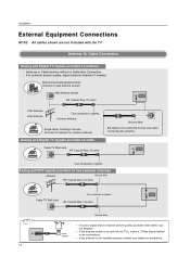
...to tighten. OPTICAL DIGITAL AUDIO OUT OPTICAL DIGITAL AUDIO OUT VIDE S-VID IDfIGtIThOALUeATUDaIOntenSn-VIaDEOisVIDnEOot ( ) inAUsDtIOalled properly, contact your dealer for two TV's, install a "2-Way Signal Splitter" • in the connections. ANTENNA/ CABLE IN Turn clockwise to tighten. Multi-family Dwellings/Apartments... - Installation External Equipment Connections NOTE: All cables shown are not included with the TV Antenna Or Cable Connection Analog and Digital TV signals provided on cable Cable TV Wall Jack RF Coaxial Wire (75 ohm) Bronze Wire Be careful not to be...
...to tighten. OPTICAL DIGITAL AUDIO OUT OPTICAL DIGITAL AUDIO OUT VIDE S-VID IDfIGtIThOALUeATUDaIOntenSn-VIaDEOisVIDnEOot ( ) inAUsDtIOalled properly, contact your dealer for two TV's, install a "2-Way Signal Splitter" • in the connections. ANTENNA/ CABLE IN Turn clockwise to tighten. Multi-family Dwellings/Apartments... - Installation External Equipment Connections NOTE: All cables shown are not included with the TV Antenna Or Cable Connection Analog and Digital TV signals provided on cable Cable TV Wall Jack RF Coaxial Wire (75 ohm) Bronze Wire Be careful not to be...

Owners Manual
Page 19
...OUTPUT SWITCH IN 34 VIDEO AUDIO ANT OUT 1 OPTICAL DIGITAL AUDIO ( ) VIDEOS-VIDEO VIDEOAUDIO AUDIO OUT 1 Connect the AUDIO/VIDEO jacks between the VCR and TV. - Match the jack colors (Video = yellow, Audio Left = white, and Audio Right = red) 2 Insert a video tape into the VCR and ... ( ) VIDAEUODIO AUDIO 19 COMPONENT IN AV OUT AV IN 1 COMPONENT IN AV OUT A To avoid picture noise (interference), leave an adequate distance between TV and VCR. Installation VCR Setup - When connecting with an antenna 2 VCR ANT IN ANT OUT S-VIDEO OUT OUTPUT SWITCH 34 (R) AUDIO (L) IN VIDEO ...
...OUTPUT SWITCH IN 34 VIDEO AUDIO ANT OUT 1 OPTICAL DIGITAL AUDIO ( ) VIDEOS-VIDEO VIDEOAUDIO AUDIO OUT 1 Connect the AUDIO/VIDEO jacks between the VCR and TV. - Match the jack colors (Video = yellow, Audio Left = white, and Audio Right = red) 2 Insert a video tape into the VCR and ... ( ) VIDAEUODIO AUDIO 19 COMPONENT IN AV OUT AV IN 1 COMPONENT IN AV OUT A To avoid picture noise (interference), leave an adequate distance between TV and VCR. Installation VCR Setup - When connecting with an antenna 2 VCR ANT IN ANT OUT S-VIDEO OUT OUTPUT SWITCH 34 (R) AUDIO (L) IN VIDEO ...
Owners Manual
Page 20
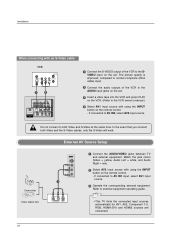
... on the set. External AV Source Setup Camcorder Video Game Set 1 L AUDIO R VIDEO 1 Connect the AUDIO/VIDEO jacks between TV and external equipment. If connected to external equipment operating guide. • This TV finds the connected input sources automatically for AV1, AV2, Component 1-2, RGB, HDMI1/DVI and HDMI2 sources are connected. 20
... on the set. External AV Source Setup Camcorder Video Game Set 1 L AUDIO R VIDEO 1 Connect the AUDIO/VIDEO jacks between TV and external equipment. If connected to external equipment operating guide. • This TV finds the connected input sources automatically for AV1, AV2, Component 1-2, RGB, HDMI1/DVI and HDMI2 sources are connected. 20
Owners Manual
Page 21
... DVD to the DVD player's manual for operating instructions. VIDEO AUDIO COMPONENT IN AV OUT AV IN 1 OPTICAL DIGITAL AUDIO OUT S-VIDEO VIDEO ( ) AUDIO • TV can receive the video and audio signal simultaneously with using a HDMI cable. • If the DVD supports Auto HDMI function, the DVD output resolution will...
... DVD to the DVD player's manual for operating instructions. VIDEO AUDIO COMPONENT IN AV OUT AV IN 1 OPTICAL DIGITAL AUDIO OUT S-VIDEO VIDEO ( ) AUDIO • TV can receive the video and audio signal simultaneously with using a HDMI cable. • If the DVD supports Auto HDMI function, the DVD output resolution will...
Owners Manual
Page 22
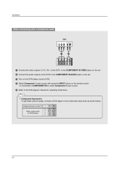
Component ports on the TV Video output ports on the remote control. - Installation When connecting with a component cable DVD B R (R) AUDIO (L) 1 2 VIDEO AUDIO ANTENNA/ CABLE IN HDMI / DVI IN COMPONENT IN 1 ...
Component ports on the TV Video output ports on the remote control. - Installation When connecting with a component cable DVD B R (R) AUDIO (L) 1 2 VIDEO AUDIO ANTENNA/ CABLE IN HDMI / DVI IN COMPONENT IN 1 ...
Owners Manual
Page 23
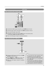
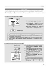
...box.) HDMI-DTV OUTPUT Digital Set-top Box COMPONENT IN AV OUT AV IN 1 RGB IN (PC) AUDIO IN REMOTE (RGB/DVI) CONTROL IN • TV can receive Digital Over-the-air/Cable signals without an external digital set -top box. (Refer to COMPONENT IN 2, select Component 2 input source. However, ...if you need to 1280x720p. When connecting with using the INPUT button on the remote control. 3 Turn on the remote control. - This TV can receive the video and audio signal simultaneously using the INPUT button on the digital set -top box. Installation HDSTB Setup -
...box.) HDMI-DTV OUTPUT Digital Set-top Box COMPONENT IN AV OUT AV IN 1 RGB IN (PC) AUDIO IN REMOTE (RGB/DVI) CONTROL IN • TV can receive Digital Over-the-air/Cable signals without an external digital set -top box. (Refer to COMPONENT IN 2, select Component 2 input source. However, ...if you need to 1280x720p. When connecting with using the INPUT button on the remote control. 3 Turn on the remote control. - This TV can receive the video and audio signal simultaneously using the INPUT button on the digital set -top box. Installation HDSTB Setup -

Owners Manual
Page 25
...AUDIO OPTICAL DIGITAL AUDIO OUT S-VIDEO VIDEO (MONO) AUDIO 1/2 1 Connect one end of an optical cable to the TV Digital Audio Optical Output port. 2 Connect the other end of the second TV or monitor for further details regarding that device's input settings. 1/2 S-VIDEO IN (R) AUDIO (L) VIDEO • Component... DIGITAL AUDIO OUT S-VIDEO VIDEO (MONO) AUDIO 1 Connect the second TV or monitor to the TV's AV OUT jacks. 2 See the Operating Manual of the optical cable to hook up a second TV or monitor. The TV has a special signal output capability which allows you to the digital audio...
...AUDIO OPTICAL DIGITAL AUDIO OUT S-VIDEO VIDEO (MONO) AUDIO 1/2 1 Connect one end of an optical cable to the TV Digital Audio Optical Output port. 2 Connect the other end of the second TV or monitor for further details regarding that device's input settings. 1/2 S-VIDEO IN (R) AUDIO (L) VIDEO • Component... DIGITAL AUDIO OUT S-VIDEO VIDEO (MONO) AUDIO 1 Connect the second TV or monitor to the TV's AV OUT jacks. 2 See the Operating Manual of the optical cable to hook up a second TV or monitor. The TV has a special signal output capability which allows you to the digital audio...


