

User Guide
Page 2
...been engineered and manufactured to ensure your personal safety, however improper use , and servicing. In order to be left unattended for replacement. The power supply cord is OFF. Ensure that have in a shock or fire hazard. There are Dangerous High Voltages inside . Some internal parts carry ... manual or listed on a sloping shelf unless properly secured. Use only a stand recommended by the supplier. On Safety Use only the power cord supplied with your service technician for an extended period of this display, observe the following basic rules for its installation, use may...
...been engineered and manufactured to ensure your personal safety, however improper use , and servicing. In order to be left unattended for replacement. The power supply cord is OFF. Ensure that have in a shock or fire hazard. There are Dangerous High Voltages inside . Some internal parts carry ... manual or listed on a sloping shelf unless properly secured. Use only a stand recommended by the supplier. On Safety Use only the power cord supplied with your service technician for an extended period of this display, observe the following basic rules for its installation, use may...

User Guide
Page 3
... or Blue spots on the screen. Use a slightly damp (not wet) cloth. Do not use this display near water such as near or over the power cord, and do not place the display where the power cord is provided. Disposal of the display screen.
... or Blue spots on the screen. Use a slightly damp (not wet) cloth. Do not use this display near water such as near or over the power cord, and do not place the display where the power cord is provided. Disposal of the display screen.

User Guide
Page 4
... is turned off. The product may differ from the items shown in the figure. Connecting the Display Before setting up the monitor, ensure that the power to disconnect it. Once you connect the stand base, try not to the monitor, the computer system, and other hand, as shown in the picture...
... is turned off. The product may differ from the items shown in the figure. Connecting the Display Before setting up the monitor, ensure that the power to disconnect it. Once you connect the stand base, try not to the monitor, the computer system, and other hand, as shown in the picture...

User Guide
Page 5
A4 Adjust the position of the monitor should not exceed 5 degrees. Positioning your display 1. Connecting the Display Before setting up the monitor, ensure that the power to the monitor, the computer system, and other attached devices is recommended that in order to maintain an ergonomic and comfortable viewing position, the forward tilt angle of the panel in various ways for maximum comfort. Tilt Range : -5˚~25˚ Ergonomic It is turned off.
A4 Adjust the position of the monitor should not exceed 5 degrees. Positioning your display 1. Connecting the Display Before setting up the monitor, ensure that the power to the monitor, the computer system, and other attached devices is recommended that in order to maintain an ergonomic and comfortable viewing position, the forward tilt angle of the panel in various ways for maximum comfort. Tilt Range : -5˚~25˚ Ergonomic It is turned off.

User Guide
Page 6
...outlet type 2 1 PC-outlet type PC PC DVI-D(Optional) MAC Mac adapter For Apple Macintosh use , or wish to the display. When monitor power is turned on the front panel of the rear view. Otherwise, you want to adjust the monitor while in a convenient, well-ventilated location near ... is needed to change the 15 pin high density (3 row) D-sub VGA connector on the supplied cable to a 15 pin 2 row connector. 4. Power Cord Signal Cable Varies according to secure the connection. 3. This function provides the user with optimal display settings.When the user connects the monitor for...
...outlet type 2 1 PC-outlet type PC PC DVI-D(Optional) MAC Mac adapter For Apple Macintosh use , or wish to the display. When monitor power is turned on the front panel of the rear view. Otherwise, you want to adjust the monitor while in a convenient, well-ventilated location near ... is needed to change the 15 pin high density (3 row) D-sub VGA connector on the supplied cable to a 15 pin 2 row connector. 4. Power Cord Signal Cable Varies according to secure the connection. 3. This function provides the user with optimal display settings.When the user connects the monitor for...

User Guide
Page 8
A7 If the display is 17 inch monitor : 1280x1024 19 inch monitor : 1280x1024 Power Button Power Indicator Use this button to turn the display on or off. This Indicator lights up blue when the display operates normally(On Mode). Control Panel ...
A7 If the display is 17 inch monitor : 1280x1024 19 inch monitor : 1280x1024 Power Button Power Indicator Use this button to turn the display on or off. This Indicator lights up blue when the display operates normally(On Mode). Control Panel ...

User Guide
Page 10
... screen To adjust the position of the screen To improve the clarity and stability of the screen SETUP LANGUAGE OSD HORIZONTAL POSITION VERTICAL WHITE BALANCE POWER INDICATOR FACTORY RESET FLATRON MOVIE / TEXT F-ENGINE(- ) USER NORMAL To customize the screen status for a user's operating environment To select or customize desired image settings...
... screen To adjust the position of the screen To improve the clarity and stability of the screen SETUP LANGUAGE OSD HORIZONTAL POSITION VERTICAL WHITE BALANCE POWER INDICATOR FACTORY RESET FLATRON MOVIE / TEXT F-ENGINE(- ) USER NORMAL To customize the screen status for a user's operating environment To select or customize desired image settings...

User Guide
Page 13
... position of the display. Use this function when white and black colors are displayed. If you set ON at any time, the power indicator will go off. This item allows you set OFF, it will automatically be enabled only when the input signal is different the... required specifications, the color level may deteriorate due to video signal distortion. MENU - SETUP Hz + SET WHITE BALANCE Hz MENU - + SET POWER MENU : Exit +- : Adjust : Adjust INDICATOR SET : Select another sub-menu SETUP SETUP LANGUAGE To choose the language in which the control names ...
... position of the display. Use this function when white and black colors are displayed. If you set ON at any time, the power indicator will go off. This item allows you set OFF, it will automatically be enabled only when the input signal is different the... required specifications, the color level may deteriorate due to video signal distortion. MENU - SETUP Hz + SET WHITE BALANCE Hz MENU - + SET POWER MENU : Exit +- : Adjust : Adjust INDICATOR SET : Select another sub-menu SETUP SETUP LANGUAGE To choose the language in which the control names ...

User Guide
Page 15
... appears when the signal cable between your PC and your display again. This message appears when the signal from the PC (video card) is in power saving mode, try again. Do you see "OSD LOCKED" when you see a "OSD LOCKED" message on the screen? Adjust the brightness and the contrast....time by pushing the MENU button for service. You can unlock the OSD controls at any key on the PC. Check and see if the power cord is not connected. See the 'Specifications' section of this manual and configure your display is connected properly to turn on the keyboard to ...
... appears when the signal cable between your PC and your display again. This message appears when the signal from the PC (video card) is in power saving mode, try again. Do you see "OSD LOCKED" when you see a "OSD LOCKED" message on the screen? Adjust the brightness and the contrast....time by pushing the MENU button for service. You can unlock the OSD controls at any key on the PC. Check and see if the power cord is not connected. See the 'Specifications' section of this manual and configure your display is connected properly to turn on the keyboard to ...
User Guide
Page 16
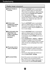
... and adjust the display to the recommended resolution or adjust the display image to the recommend resolution. The screen color is incorrect. Make sure the power voltage is set to interlace mode and if yes, change it to the ideal setting. Press the AUTO/SET button to automatically adjust your display...
... and adjust the display to the recommended resolution or adjust the display image to the recommend resolution. The screen color is incorrect. Make sure the power voltage is set to interlace mode and if yes, change it to the ideal setting. Press the AUTO/SET button to automatically adjust your display...

User Guide
Page 18
... Green) ,Digital 15 pin D-Sub Connector DVI - Specifications 17inch Display Sync Input Video Input Resolution Plug&Play Power Consumption Dimensions &Weight (with tilt stand) Tilt Range Power Input Environmental Conditions Tilt Stand Signal cable Power cord 17 inches (43.2cm) Flat Panel Active matrix-TFT LCD Anti-Glare coating 17 inches viewable 0.264...
... Green) ,Digital 15 pin D-Sub Connector DVI - Specifications 17inch Display Sync Input Video Input Resolution Plug&Play Power Consumption Dimensions &Weight (with tilt stand) Tilt Range Power Input Environmental Conditions Tilt Stand Signal cable Power cord 17 inches (43.2cm) Flat Panel Active matrix-TFT LCD Anti-Glare coating 17 inches viewable 0.264...

User Guide
Page 19
Specifications 19inch Display Sync Input Video Input Resolution Plug&Play Power Consumption Dimensions &Weight (with tilt stand) Tilt Range Power Input Environmental Conditions Tilt Stand Signal cable Power cord 19 inches (48.19cm) Flat Panel Active matrix-TFT LCD Anti-Glare coating 19 inches viewable 0.294 mm pixel pitch Horizontal Freq. Input Form ...
Specifications 19inch Display Sync Input Video Input Resolution Plug&Play Power Consumption Dimensions &Weight (with tilt stand) Tilt Range Power Input Environmental Conditions Tilt Stand Signal cable Power cord 19 inches (48.19cm) Flat Panel Active matrix-TFT LCD Anti-Glare coating 19 inches viewable 0.294 mm pixel pitch Horizontal Freq. Input Form ...

User Guide
Page 21
...Signal(DVI-D) Pin Signal(DVI-D) 1 T. Data2+ 17 T. Data0- 3 T. D. M. Data5- 6 DDC Clock 21 T. D. M. Clock+ 9 T. M. D. S. D. M. S. (Transition Minimized Differential Signaling) A20 D. M. S. Data2/4 Shield 18 T. M. D. M. D. S. S. M. Data3+ 14 +5V Power 15 Ground (return for +5V, H. D. Data0+ 4 T. Data4- 19 T. D. M. Clock- 10 T. D. S. Data3- 13 T. Sync. M. Data2- 16 Hot Plug Detect 2 T. M. S. S. Data4+ 20 T. S. D. S. D. M. D. Data1- 24 T. D. S. D. S. M. Data5+ 7 DDC...
...Signal(DVI-D) Pin Signal(DVI-D) 1 T. Data2+ 17 T. Data0- 3 T. D. M. Data5- 6 DDC Clock 21 T. D. M. Clock+ 9 T. M. D. S. D. M. S. (Transition Minimized Differential Signaling) A20 D. M. S. Data2/4 Shield 18 T. M. D. M. D. S. S. M. Data3+ 14 +5V Power 15 Ground (return for +5V, H. D. Data0+ 4 T. Data4- 19 T. D. M. Clock- 10 T. D. S. Data3- 13 T. Sync. M. Data2- 16 Hot Plug Detect 2 T. M. S. S. Data4+ 20 T. S. D. S. D. M. D. Data1- 24 T. D. S. D. S. M. Data5+ 7 DDC...


