

Owner's Manual
Page 1
has determined that this product meets the ENERGY STAR guidelines for energy efficiency. © Copyright 2008, LG Electronics USA, Inc. Environmental Protection Agency (EPA). As an ENERGY STAR Partner LG Electronics USA, Inc. Installation and Operating Guide Model Numbers | Z42PG10, Z50PG10 | PLASMA TV ENERGY STAR is a set of power-saving guidelines issued by the U.S.
has determined that this product meets the ENERGY STAR guidelines for energy efficiency. © Copyright 2008, LG Electronics USA, Inc. Environmental Protection Agency (EPA). As an ENERGY STAR Partner LG Electronics USA, Inc. Installation and Operating Guide Model Numbers | Z42PG10, Z50PG10 | PLASMA TV ENERGY STAR is a set of power-saving guidelines issued by the U.S.

Owner's Manual
Page 2
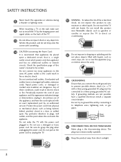
... without written authorization from that may cause harmful interference to persons. If this product A Consult the dealer or an experienced radio/TV technician for proper grounding and, in particular, specifies that interference will not occur in accordance with arrowhead symbol, within the product's... the FCC Rules. This equipment generates, uses and can be determined by turning the equipment off and on a circuit different from LG Electronics. Any changes or modifications not expressly approved by one or more of the cable entry as practical. REFER TO QUALIFIED SERVICE ...
... without written authorization from that may cause harmful interference to persons. If this product A Consult the dealer or an experienced radio/TV technician for proper grounding and, in particular, specifies that interference will not occur in accordance with arrowhead symbol, within the product's... the FCC Rules. This equipment generates, uses and can be determined by turning the equipment off and on a circuit different from LG Electronics. Any changes or modifications not expressly approved by one or more of the cable entry as practical. REFER TO QUALIFIED SERVICE ...
Owner's Manual
Page 4
... cups, etc. Protect the power cord from direct sunlight. 2 Do not make sure 12 not to a three-prong grounded AC outlet). a TV with liquids, such as being twisted, kinked, pinched, closed in . Short-circuit Breaker Power Supply 18 DISCONNECTING DEVICE FROM MAINS Mains plug is recommend...additional outlets or branch circuits. that is, a single outlet circuit which powers only that you connect the earth ground wire to unplug the TV. 15 WARNING - Overloaded wall outlets, loose or damaged wall outlets, extension cords, frayed power cords, or damaged or cracked wire insulation ...
... cups, etc. Protect the power cord from direct sunlight. 2 Do not make sure 12 not to a three-prong grounded AC outlet). a TV with liquids, such as being twisted, kinked, pinched, closed in . Short-circuit Breaker Power Supply 18 DISCONNECTING DEVICE FROM MAINS Mains plug is recommend...additional outlets or branch circuits. that is, a single outlet circuit which powers only that you connect the earth ground wire to unplug the TV. 15 WARNING - Overloaded wall outlets, loose or damaged wall outlets, extension cords, frayed power cords, or damaged or cracked wire insulation ...
Owner's Manual
Page 5
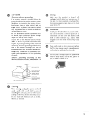
...cables have been removed. It may occur. Do not clean with a soft cloth to provide some protection against or put stress on the TV as to prevent scratching. Ground Clamp Electric Service Equipment NEC: National Electrical Code Antenna Lead in the U.S.A. Antenna grounding according to the National... a bookcase. Do not install in the vicinity of overhead power lines or other liquids directly on the front panel of the TV. 23 Ventilation Install your TV where there is installed, follow the precautions below. An outdoor antenna system should not be located in a confined space such as...
...cables have been removed. It may occur. Do not clean with a soft cloth to provide some protection against or put stress on the TV as to prevent scratching. Ground Clamp Electric Service Equipment NEC: National Electrical Code Antenna Lead in the U.S.A. Antenna grounding according to the National... a bookcase. Do not install in the vicinity of overhead power lines or other liquids directly on the front panel of the TV. 23 Ventilation Install your TV where there is installed, follow the precautions below. An outdoor antenna system should not be located in a confined space such as...
Owner's Manual
Page 6
...PICTURE CONTROL Picture Size (Aspect Ratio) Control 44 Preset Picture Settings - CONTENTS WARNING / CAUTION A SAFETY INSTRUCTIONS 1 FEATURE OF THIS TV 6 PREPARATION Accessories 7 Front Panel Information 8 Back Panel Information 9 Stand Instruction 10 Cable Management 11 Desktop Pedestal Installation 12 VESA Wall Mounting... 13 Securing the TV to the wall to prevent falling when the TV is used on a stand 14 Antenna or Cable Connection 15 EXTERNAL EQUIPMENT SETUP HD Receiver Setup ...
...PICTURE CONTROL Picture Size (Aspect Ratio) Control 44 Preset Picture Settings - CONTENTS WARNING / CAUTION A SAFETY INSTRUCTIONS 1 FEATURE OF THIS TV 6 PREPARATION Accessories 7 Front Panel Information 8 Back Panel Information 9 Stand Instruction 10 Cable Management 11 Desktop Pedestal Installation 12 VESA Wall Mounting... 13 Securing the TV to the wall to prevent falling when the TV is used on a stand 14 Antenna or Cable Connection 15 EXTERNAL EQUIPMENT SETUP HD Receiver Setup ...
Owner's Manual
Page 7
User Mode 59 Balance 60 TV Speakers On/Off Setup 61 Audio Reset 62 Stereo/SAP Broadcasts Setup 63 Audio Language 64 On-Screen Menus Language Selection 65 Caption Mode - Digital .../Off Time Setting 71 Sleep Timer Setting 72 Auto Shut-off Setting 73 PARENTAL CONTROL / RATINGS Set Password & Lock System 74 Channel Blocking 77 Movie & TV Rating 78 Downloadable Rating 83 External Input Blocking 84 Key lock 85 APPENDIX Troubleshooting 86 Maintenance 88 Product Specifications 89 IR Codes 90 External Control...
User Mode 59 Balance 60 TV Speakers On/Off Setup 61 Audio Reset 62 Stereo/SAP Broadcasts Setup 63 Audio Language 64 On-Screen Menus Language Selection 65 Caption Mode - Digital .../Off Time Setting 71 Sleep Timer Setting 72 Auto Shut-off Setting 73 PARENTAL CONTROL / RATINGS Set Password & Lock System 74 Channel Blocking 77 Movie & TV Rating 78 Downloadable Rating 83 External Input Blocking 84 Key lock 85 APPENDIX Troubleshooting 86 Maintenance 88 Product Specifications 89 IR Codes 90 External Control...

Owner's Manual
Page 8
Manufactured under license from Dolby Laboratories. "Dolby "and the double-D symbol are trademarks of SRS Labs, Inc. TruSurround XT technology is a trademark of Dolby Laboratories. 6 FEATURE OF THIS TV is incorporated under license from SRS Labs, Inc.
Manufactured under license from Dolby Laboratories. "Dolby "and the double-D symbol are trademarks of SRS Labs, Inc. TruSurround XT technology is a trademark of Dolby Laboratories. 6 FEATURE OF THIS TV is incorporated under license from SRS Labs, Inc.
Owner's Manual
Page 9
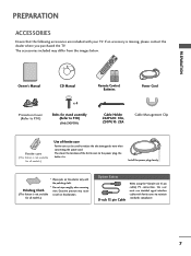
...Power Cord Protection Cover (Refer to P.10) x 4 Bolts for stand assembly (Refer to P.10) (Only Z42PG10) Cable Holder Z42PG10: 1EA, Z50PG10: 2EA Cable Management Clip Ferrite core (This feature is . Excessive pressure may differ from the images below. PREPARATION PREPARATION ACCESSORIES Ensure that the following... pin Cable When using the VGA (D-sub 15 pin cable) PC connection, the user must use shielded signal interface cables with your TV. If an accessory is not available scratch or discoloration. Install the power plug closely. * Wipe spots on the exterior only with ...
...Power Cord Protection Cover (Refer to P.10) x 4 Bolts for stand assembly (Refer to P.10) (Only Z42PG10) Cable Holder Z42PG10: 1EA, Z50PG10: 2EA Cable Management Clip Ferrite core (This feature is . Excessive pressure may differ from the images below. PREPARATION PREPARATION ACCESSORIES Ensure that the following... pin Cable When using the VGA (D-sub 15 pin cable) PC connection, the user must use shielded signal interface cables with your TV. If an accessory is not available scratch or discoloration. Install the power plug closely. * Wipe spots on the exterior only with ...
Owner's Manual
Page 10
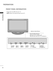
PREPARATION PREPARATION FRONT PANEL INFORMATION I NOTE: Remove any protective tape from your TV. INPUT MENU ENTER VOL INPUT MENU POWER Button ENTER INPUT Button VOL MENU Button CH ENTER Button VOLUME (-, +) Buttons CH CHANNEL (E,D)Buttons 8 Remote Control Sensor Power/Standby Indicator Illuminates red in standby mode. Illuminates blue when the TV is switched on. I Image shown may differ from the TV.
PREPARATION PREPARATION FRONT PANEL INFORMATION I NOTE: Remove any protective tape from your TV. INPUT MENU ENTER VOL INPUT MENU POWER Button ENTER INPUT Button VOL MENU Button CH ENTER Button VOLUME (-, +) Buttons CH CHANNEL (E,D)Buttons 8 Remote Control Sensor Power/Standby Indicator Illuminates red in standby mode. Illuminates blue when the TV is switched on. I Image shown may differ from the TV.
Owner's Manual
Page 11
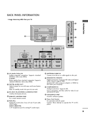
...CONTROL PORT For a wired remote control. 5 RGB (PC) Analog PC Connection. Supports HD. Accepts DVI video using an adapter or HDMI to operate the TV on DC power. 9 Uses a D-sub 15 pin cable (VGA cable). AUDIO (RGB/DVI) 1/8" headphone jack for use with AC power. Doesn't ... mode, this jack. 7 HDMI/DVI IN, HDMI IN Digital Connection. R HDMI IN 3 SERVICE ONLY USB PREPARATION BACK PANEL INFORMATION I Image shown may differ from your TV. 9 7 10 1 R VIDEO L/MONO AUDIO R 3 RS-232C IN (CONTROL & SERVICE) 4 5 ANTENNA/ CABLE IN 6 RGB IN RGB(PC) AUDIO (RGB/DVI) 7 AV IN 2 ...
...CONTROL PORT For a wired remote control. 5 RGB (PC) Analog PC Connection. Supports HD. Accepts DVI video using an adapter or HDMI to operate the TV on DC power. 9 Uses a D-sub 15 pin cable (VGA cable). AUDIO (RGB/DVI) 1/8" headphone jack for use with AC power. Doesn't ... mode, this jack. 7 HDMI/DVI IN, HDMI IN Digital Connection. R HDMI IN 3 SERVICE ONLY USB PREPARATION BACK PANEL INFORMATION I Image shown may differ from your TV. 9 7 10 1 R VIDEO L/MONO AUDIO R 3 RS-232C IN (CONTROL & SERVICE) 4 5 ANTENNA/ CABLE IN 6 RGB IN RGB(PC) AUDIO (RGB/DVI) 7 AV IN 2 ...
Owner's Manual
Page 12
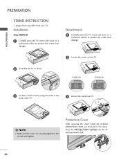
... shown. PREPARATION PREPARATION STAND INSTRUCTION I Image shown may differ from damage. Press the PROTECTION COVER into the TV until you hear it click. 10 NOTE G Make sure the screws are securely tightened, but do not over the hole for the stand. Protection ...Cover After removing the stand, install the included protection cover over -tighten. Z42PG10 Z50PG10 3 Fix the 4 bolts securely using the holes in the back of the TV. 3 Detach the stand from damage. 2 Loosen the screws on a cushioned surface to protect the screen from your...
... shown. PREPARATION PREPARATION STAND INSTRUCTION I Image shown may differ from damage. Press the PROTECTION COVER into the TV until you hear it click. 10 NOTE G Make sure the screws are securely tightened, but do not over the hole for the stand. Protection ...Cover After removing the stand, install the included protection cover over -tighten. Z42PG10 Z50PG10 3 Fix the 4 bolts securely using the holes in the back of the TV. 3 Detach the stand from damage. 2 Loosen the screws on a cushioned surface to protect the screen from your...

Owner's Manual
Page 13
... the cables as necessary. PREPARATION CABLE MANAGEMENT I Image shown may be injured or the TV may differ from your TV has the CABLE HOLDER, install it as shown and bundle the cables. Z50PG10 G Hold the CABLE MANAGEMENT CLIP with both hands and pull it upward. To connect additional equipment, see the EXTERNAL EQUIPMENT...
... the cables as necessary. PREPARATION CABLE MANAGEMENT I Image shown may be injured or the TV may differ from your TV has the CABLE HOLDER, install it as shown and bundle the cables. Z50PG10 G Hold the CABLE MANAGEMENT CLIP with both hands and pull it upward. To connect additional equipment, see the EXTERNAL EQUIPMENT...

Owner's Manual
Page 14
G Do not mount near or above any type of 4 inches on all four sides from your TV. PREPARATION PREPARATION DESKTOP PEDESTAL INSTALLATION I Image shown may differ from the wall. 4 inches 4 inches 4 inches 4 inches CAUTION G Ensure adequate ventilation by following the clearance recommendations. For proper ventilation, allow a clearance of heat source. 12
G Do not mount near or above any type of 4 inches on all four sides from your TV. PREPARATION PREPARATION DESKTOP PEDESTAL INSTALLATION I Image shown may differ from the wall. 4 inches 4 inches 4 inches 4 inches CAUTION G Ensure adequate ventilation by following the clearance recommendations. For proper ventilation, allow a clearance of heat source. 12
Owner's Manual
Page 15
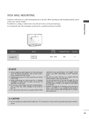
LG recommends that do not comply with the mount. G For wall mounts...MOUNTING Install your wall mount on a solid wall perpendicular to electric shock. 13 When attaching to follow the TV installation instructions. A B Product PLASMA TV Model Z42PG10 Z50PG10 VESA (A * B) Standard Screw Quantity 400 * 400 M6 4 ! G Do not use screws longer ...other building materials, please contact your nearest installer. CAUTION G Do not install your wall mount kit while your TV is not liable for wall mount kits are provided. NOTE G Screw length needed depends on their specifications. ...
LG recommends that do not comply with the mount. G For wall mounts...MOUNTING Install your wall mount on a solid wall perpendicular to electric shock. 13 When attaching to follow the TV installation instructions. A B Product PLASMA TV Model Z42PG10 Z50PG10 VESA (A * B) Standard Screw Quantity 400 * 400 M6 4 ! G Do not use screws longer ...other building materials, please contact your nearest installer. CAUTION G Do not install your wall mount kit while your TV is not liable for wall mount kits are provided. NOTE G Screw length needed depends on their specifications. ...
Owner's Manual
Page 16
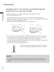
... rope so it becomes horizontal between the wall and the product. ! Match the height of the bracket on the wall and the one on the TV are tightened securely. NOTE G Use a platform or cabinet strong enough and large enough to the holes in the upper holes. I Image shown may differ from... in the eye-bolts position before inserting the eye-bolts, loosen the bolts. * Insert the eye-bolts or TV brackets/bolts and tighten them securely in the product. I Insert the eye-bolts (or TV brackets and bolts) to tighten the product to tie the product. Caution: Please make sure that the height...
... rope so it becomes horizontal between the wall and the product. ! Match the height of the bracket on the wall and the one on the TV are tightened securely. NOTE G Use a platform or cabinet strong enough and large enough to the holes in the upper holes. I Image shown may differ from... in the eye-bolts position before inserting the eye-bolts, loosen the bolts. * Insert the eye-bolts or TV brackets/bolts and tighten them securely in the product. I Insert the eye-bolts (or TV brackets and bolts) to tighten the product to tie the product. Caution: Please make sure that the height...

Owner's Manual
Page 17
ANTENNA OR CABLE CONNECTION R 1. I If the antenna is not installed properly, contact your dealer for two TV's, install a 2-Way Signal Splitter. I If the antenna needs to be split for assistance. 15 Wall Antenna Socket Multi-family Dwellings/Apartments (Connect ...Antenna (Analog or Digital) Wall Antenna Socket or Outdoor Antenna without a Cable Box Connection. For optimum picture quality, adjust antenna direction if needed. Cable Cable TV Wall Jack RF Coaxial Wire (75 ohm) ANTENNA/ CABLE IN I To prevent damage do not connect to bend the copper wire when connecting the antenna....
ANTENNA OR CABLE CONNECTION R 1. I If the antenna is not installed properly, contact your dealer for two TV's, install a 2-Way Signal Splitter. I If the antenna needs to be split for assistance. 15 Wall Antenna Socket Multi-family Dwellings/Apartments (Connect ...Antenna (Analog or Digital) Wall Antenna Socket or Outdoor Antenna without a Cable Box Connection. For optimum picture quality, adjust antenna direction if needed. Cable Cable TV Wall Jack RF Coaxial Wire (75 ohm) ANTENNA/ CABLE IN I To prevent damage do not connect to bend the copper wire when connecting the antenna....
Owner's Manual
Page 18
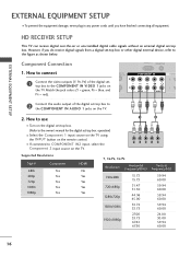
..., never plug in any power cords until you do receive digital signals from a digital set -top box to the COMPONENT IN AUDIO 1 jacks on the TV. 2. Match the jack colors (Y = green, PB = blue, and( ) PR = red). How to connect MOTE TROL IN 2 1 Connect the video outputs (Y, PB, PR...other digital external device, refer to the figure as shown below. operation) I If connected to COMPONENT IN2 input, select the Component 2 input source on the TV. 1 2 Y PB PR L R Supported Resolutions Signal 480i 480p 720p 1080i 1080p Component Yes Yes Yes Yes Yes HDMI No Yes Yes Yes Yes Y, CB...
..., never plug in any power cords until you do receive digital signals from a digital set -top box to the COMPONENT IN AUDIO 1 jacks on the TV. 2. Match the jack colors (Y = green, PB = blue, and( ) PR = red). How to connect MOTE TROL IN 2 1 Connect the video outputs (Y, PB, PR...other digital external device, refer to the figure as shown below. operation) I If connected to COMPONENT IN2 input, select the Component 2 input source on the TV. 1 2 Y PB PR L R Supported Resolutions Signal 480i 480p 720p 1080i 1080p Component Yes Yes Yes Yes Yes HDMI No Yes Yes Yes Yes Y, CB...
Owner's Manual
Page 19
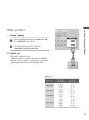
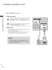
... digital set -top box to connect 1 Connect the digital set -top box.) I Select the HDMI1, HDMI2, or HDMI3 input source on the TV using the INPUT button on the TV. 2 No separate audio connection is necessary. ( ) HDMI supports both audio and video. 2. How to HDMI/DVI IN1, 2, or HDMI IN3 jack on...
... digital set -top box to connect 1 Connect the digital set -top box.) I Select the HDMI1, HDMI2, or HDMI3 input source on the TV using the INPUT button on the TV. 2 No separate audio connection is necessary. ( ) HDMI supports both audio and video. 2. How to HDMI/DVI IN1, 2, or HDMI IN3 jack on...
Owner's Manual
Page 20
How to connect 1 Connect the DVI output of the digital set -top box.) I Select the HDMI1, HDMI2, or HDMI3 input source on the TV using the INPUT button on the TV. 2. RGB IN RGB(PC) AUDIO (RGB/DVI) CABLE IN COMPONENT IN PB PR L R VIDEO AUDIO HDMI/DVI IN 2 1 2 1 ! DVI doesn't support ...-DTV OUTPUT 18 How to use ( ) I Turn on the digital set-top box. (Refer to the HDMI/DVI IN1, 2, or HDMI IN3 jack on the TV. 2 Connect the audio output of the digital set-top box to the owner's manual for this connection. EXTERNAL EQUIPMENT SETUP EXTERNAL EQUIPMENT SETUP DVI to...
How to connect 1 Connect the DVI output of the digital set -top box.) I Select the HDMI1, HDMI2, or HDMI3 input source on the TV using the INPUT button on the TV. 2. RGB IN RGB(PC) AUDIO (RGB/DVI) CABLE IN COMPONENT IN PB PR L R VIDEO AUDIO HDMI/DVI IN 2 1 2 1 ! DVI doesn't support ...-DTV OUTPUT 18 How to use ( ) I Turn on the digital set-top box. (Refer to the HDMI/DVI IN1, 2, or HDMI IN3 jack on the TV. 2 Connect the audio output of the digital set-top box to the owner's manual for this connection. EXTERNAL EQUIPMENT SETUP EXTERNAL EQUIPMENT SETUP DVI to...
Owner's Manual
Page 21
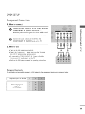
... DVD to the component input ports as shown below. I Select the Component 1 input source on the TV using the INPUT button on the TV. I Turn on the TV. Component ports on the TV Y Y Video output ports Y on the TV. O 1 ( ) RGB(PC) AUDIO (RGB/DVI) COMPONENT IN VIDEO AUDIO HDM 2 1 2. How to use I Refer to the...
... DVD to the component input ports as shown below. I Select the Component 1 input source on the TV using the INPUT button on the TV. I Turn on the TV. Component ports on the TV Y Y Video output ports Y on the TV. O 1 ( ) RGB(PC) AUDIO (RGB/DVI) COMPONENT IN VIDEO AUDIO HDM 2 1 2. How to use I Refer to the...


