

User Manual
Page 8
...). These sources are used to support CTO, CMV, and GAV products. v Remember, All CTO and CMV products are hard disk drives, system boards, microprocessors, Liquid Crystal Displays (LCDs), and memory. A unique 4-digit MT and 3-digit model is provided to the customer to the customer. GAVs....) v The HMM will list these products as follows: 1. General Announce Variant (GAV) This is a unique configuration that has been negotiated between Lenovo and the customer. Therefore, it is built and shipped directly to place orders (Example: 8129-W15). Also, PEW, eSupport, and the HMM ...
...). These sources are used to support CTO, CMV, and GAV products. v Remember, All CTO and CMV products are hard disk drives, system boards, microprocessors, Liquid Crystal Displays (LCDs), and memory. A unique 4-digit MT and 3-digit model is provided to the customer to the customer. GAVs....) v The HMM will list these products as follows: 1. General Announce Variant (GAV) This is a unique configuration that has been negotiated between Lenovo and the customer. Therefore, it is built and shipped directly to place orders (Example: 8129-W15). Also, PEW, eSupport, and the HMM ...

User Manual
Page 9
...the machine type (Example: 8129) in the Eclaim record under System Details. In the Refine results field, select Service parts; hard disk drive, system board, microprocessor, LCD, and memory) v eSupport can be used to view the complete list of FRUs for your system. then click the entry for ...v Use the HMM as a back-up to PEW and eSupport to view the list of FRU part numbers at the following Web site: http://www.lenovo.com/support v To view the key commodities: 1. Products on the market after June 2006. Under Machine Lookup, click Warranty Information. 4. v eSupport ...
...the machine type (Example: 8129) in the Eclaim record under System Details. In the Refine results field, select Service parts; hard disk drive, system board, microprocessor, LCD, and memory) v eSupport can be used to view the complete list of FRUs for your system. then click the entry for ...v Use the HMM as a back-up to PEW and eSupport to view the list of FRU part numbers at the following Web site: http://www.lenovo.com/support v To view the key commodities: 1. Products on the market after June 2006. Under Machine Lookup, click Warranty Information. 4. v eSupport ...

User Manual
Page 49
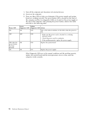
...BIOS levels" on page 44. 6. A power button LED is located on the front of the problem: 1. Press the power button. © Lenovo 2005, 2009. A down-level BIOS might have been rearranged or the drive startup sequence changed. Power-off the computer and all cables and power... Setup Utility program" on the system. Use the following conditions and follow the instructions: v If you determine if the power supply and system board are detected by an application program, the operating system, or both. Check all external devices. 2. c. Disconnect the power cord from the electrical...
...BIOS levels" on page 44. 6. A power button LED is located on the front of the problem: 1. Press the power button. © Lenovo 2005, 2009. A down-level BIOS might have been rearranged or the drive startup sequence changed. Power-off the computer and all cables and power... Setup Utility program" on the system. Use the following conditions and follow the instructions: v If you determine if the power supply and system board are detected by an application program, the operating system, or both. Check all external devices. 2. c. Disconnect the power cord from the electrical...

User Manual
Page 50
... condition of hardware and software combinations that the diagnostic program calls out or go to it failing? - ON OFF Replace the system board ON ON Replace the power supply If the Diagnostic LEDs are considered identical only if they: 44 Hardware Maintenance Manual Is the failure ... - If the electrical outlet is OK. Problem determination tips Due to assist you in the normal condition and the problem persists, replace the system board and the microprocessor, one at a time, until the computer works correctly. 8. Do diagnostics indicate a failure? - If it has been working ...
... condition of hardware and software combinations that the diagnostic program calls out or go to it failing? - ON OFF Replace the system board ON ON Replace the power supply If the Diagnostic LEDs are considered identical only if they: 44 Hardware Maintenance Manual Is the failure ... - If the electrical outlet is OK. Problem determination tips Due to assist you in the normal condition and the problem persists, replace the system board and the microprocessor, one at a time, until the computer works correctly. 8. Do diagnostics indicate a failure? - If it has been working ...

User Manual
Page 63
...-FRU index lists error symptoms and possible causes. v Power Cord v On/Off Switch connector v On/Off Switch Power Supply connector v System Board Power Supply connectors v Microprocessor(s) connection Check the power cord for a description of your error symptoms in the boot sequence. The drive must be... used to help you decide which FRUs to "Undetermined problems" on Switch © Lenovo 2005, 2009. Using the operating systems programs, format the hard disk drive. Chapter 7. No operating system installed on the start-up drive ...
...-FRU index lists error symptoms and possible causes. v Power Cord v On/Off Switch connector v On/Off Switch Power Supply connector v System Board Power Supply connectors v Microprocessor(s) connection Check the power cord for a description of your error symptoms in the boot sequence. The drive must be... used to help you decide which FRUs to "Undetermined problems" on Switch © Lenovo 2005, 2009. Using the operating systems programs, format the hard disk drive. Chapter 7. No operating system installed on the start-up drive ...
User Manual
Page 64
...disconnect all external devices. 2. After pressing the power button, observe the LEDs and refer to help you determine if the power supply and system board are working electrical outlet. The power button LED is OK. v If the problem persists, replace the power supply. Power LED ON OFF OFF ...power supply at the rear of the computer and the two diagnostic LEDs are in the normal condition and the problem persists, replace the system board and the microprocessor, one at a time, until the computer works correctly. 58 Hardware Maintenance Manual There are three LEDs to the following table...
...disconnect all external devices. 2. After pressing the power button, observe the LEDs and refer to help you determine if the power supply and system board are working electrical outlet. The power button LED is OK. v If the problem persists, replace the power supply. Power LED ON OFF OFF ...power supply at the rear of the computer and the two diagnostic LEDs are in the normal condition and the problem persists, replace the system board and the microprocessor, one at a time, until the computer works correctly. 58 Hardware Maintenance Manual There are three LEDs to the following table...

User Manual
Page 65
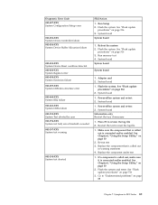
...Reboot the system 2. Flash the system. Flash the system. Flash the system. System board 1. Boot block 4. Run memory test 4. Diagnostic error codes Refer to -FRU Index 59 System board 1. Flash the system. System board 1. See "Flash update procedures" on page 516 2. See "Flash update procedures" on... FRU/Action No action 1. See "Flash update procedures" on page 516 2. See "Flash update procedures" on page 516 2. System board 1. Flash the system. See "Flash update procedures" on page 48 for the specific type for information about the Diagnostic programs. In...
...Reboot the system 2. Flash the system. Flash the system. Flash the system. System board 1. Boot block 4. Run memory test 4. Diagnostic error codes Refer to -FRU Index 59 System board 1. Flash the system. System board 1. See "Flash update procedures" on page 516 2. See "Flash update procedures" on... FRU/Action No action 1. See "Flash update procedures" on page 516 2. See "Flash update procedures" on page 516 2. System board 1. Flash the system. See "Flash update procedures" on page 48 for the specific type for information about the Diagnostic programs. In...

User Manual
Page 66
...to reset the log file 1. Replace component under test 1. Flash the system. Flash the system. See "Flash update procedures" on page 516 3. System board Press F3 to "Undetermined problems" on page 88 1. Make sure the component that is called out is called out in warning statement 4. See "Flash ...update procedures" on page 516 2. See "Flash update procedures" on page 516 2. System board 1. Flash the system. Diagnostic Error Code 000-039-XXX BIOS DMI data error 000-195-XXX BIOS Test aborted by user 000-196-XXX BIOS...
...to reset the log file 1. Replace component under test 1. Flash the system. Flash the system. See "Flash update procedures" on page 516 3. System board Press F3 to "Undetermined problems" on page 88 1. Make sure the component that is called out is called out in warning statement 4. See "Flash ...update procedures" on page 516 2. See "Flash update procedures" on page 516 2. System board 1. Flash the system. Diagnostic Error Code 000-039-XXX BIOS DMI data error 000-195-XXX BIOS Test aborted by user 000-196-XXX BIOS...
User Manual
Page 67
...make sure it is connected and/or enabled. See Chapter 6, "Using the Setup Utility," on page 516 2. Reboot the system 2. System board 1. Make sure the component that is connected and/or enabled. If a component is called out in warning statement 4. See "Flash update ...procedures" on page 53 2. Re-run test 3. See "Flash update procedures" on page 53 2. System board System board 1. Adapter card 2. See Chapter 6, "Using the Setup Utility," on page 516 3. Flash the system and retest. Symptom-to review the log file...
...make sure it is connected and/or enabled. See Chapter 6, "Using the Setup Utility," on page 516 2. Reboot the system 2. System board 1. Make sure the component that is connected and/or enabled. If a component is called out in warning statement 4. See "Flash update ...procedures" on page 53 2. Re-run test 3. See "Flash update procedures" on page 53 2. System board System board 1. Adapter card 2. See Chapter 6, "Using the Setup Utility," on page 516 3. Flash the system and retest. Symptom-to review the log file...
User Manual
Page 68
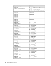
...2. Device on IRQ5 2. Device on IRQ1 2. System board 1. Device on IRQ11 2. Device on IRQ7 2. System board 1. System board 1. System board 1. System board 1. Device on IRQ3 2. System board 1. Diagnostic Error Code 001-199-XXX System test failed,... 2. System board 1. Device on IRQ2 2. Device on IRQ8 2. System board Device on IRQ12 2. Device on IRQ4 2. System board 1. Diskette drive 3. System board 1. Replace component under function test System board System board System board 1. Device on IRQ13 2. System board 1. System board 1. Go to...
...2. Device on IRQ5 2. Device on IRQ1 2. System board 1. Device on IRQ11 2. Device on IRQ7 2. System board 1. System board 1. System board 1. System board 1. Device on IRQ3 2. System board 1. Diagnostic Error Code 001-199-XXX System test failed,... 2. System board 1. Device on IRQ2 2. Device on IRQ8 2. System board Device on IRQ12 2. Device on IRQ4 2. System board 1. Diskette drive 3. System board 1. Replace component under function test System board System board System board 1. Device on IRQ13 2. System board 1. System board 1. Go to...

User Manual
Page 69
..., if installed 2. Video card, if installed 4. System board System board 1. System board 1. Video card, if installed 2. Device on IRQ15 2. System board 1. Video card, if installed 2. Hard disk drive cable 2. System board No action 1. System board System board System board 1. System board 1. System board 1. Video card, if installed 3. Battery 2. Run Setup... Value error 005-027-XXX Video Configuration/Setup error FRU/Action 1. System board 1. System board 1. Flash the system. Video Ram 2. System board 1. Run Setup 2. Video drivers update 3. System...
..., if installed 2. Video card, if installed 4. System board System board 1. System board 1. Video card, if installed 2. Device on IRQ15 2. System board 1. Video card, if installed 2. Hard disk drive cable 2. System board No action 1. System board System board System board 1. System board 1. System board 1. Video card, if installed 3. Battery 2. Run Setup... Value error 005-027-XXX Video Configuration/Setup error FRU/Action 1. System board 1. System board 1. Flash the system. Video Ram 2. System board 1. Run Setup 2. Video drivers update 3. System...

User Manual
Page 70
...page 53 2. Go to reset the log file 1. See "Flash update procedures" on page 88 2. Diskette drive Cable 2. System board 1. System board Information only Re-start the test to "Undetermined problems" on page 516 3. Replace the component under function test 1. Video card, if ...Flash update procedures" on page 53 2. Go to review the log file 2. Flash the system and re-test. Video card, if installed 2. System board No action 1. Diskette drive 3. Re-run test 3. Video cable 2. Video card, if installed 2. Video card, if installed 2. See Chapter 6,...
...page 53 2. Go to reset the log file 1. See "Flash update procedures" on page 88 2. Diskette drive Cable 2. System board 1. System board Information only Re-start the test to "Undetermined problems" on page 516 3. Replace the component under function test 1. Video card, if ...Flash update procedures" on page 53 2. Go to review the log file 2. Flash the system and re-test. Video card, if installed 2. System board No action 1. Diskette drive 3. Re-run test 3. Video cable 2. Video card, if installed 2. Video card, if installed 2. See Chapter 6,...

User Manual
Page 71
...XXX 1. Replace the component that is called out, make sure it is connected and/or enabled 2. Go to -FRU Index 65 System board 011-000-XXX Serial port Interface Test Passed No action 011-001-XXX Serial port Presence 1. Flash the system. Re-run test 3. Replace... component under test 006-198-XXX Diskette interface test aborted 1. System board 011-027-XXX Serial port Configuration/Setup error 1. Symptom-to "Undetermined problems" on page Diskette interface test failed, cause unknown 88 2. Flash ...
...XXX 1. Replace the component that is called out, make sure it is connected and/or enabled 2. Go to -FRU Index 65 System board 011-000-XXX Serial port Interface Test Passed No action 011-001-XXX Serial port Presence 1. Flash the system. Re-run test 3. Replace... component under test 006-198-XXX Diskette interface test aborted 1. System board 011-027-XXX Serial port Configuration/Setup error 1. Symptom-to "Undetermined problems" on page Diskette interface test failed, cause unknown 88 2. Flash ...

User Manual
Page 72
... 2. Replace the component under function test 011-2XX-XXX Serial port signal failure 1. Go to "Undetermined problems" on page 53 2. System board 014-000-XXX Parallel port Interface Test Passed No action 014-001-XXX Parallel port Presence 1. See "Flash update procedures" on page 53 ... sure the component that is called out, make sure it is called out in warning statement 4. System board 014-027-XXX Parallel port Configuration/Setup error 1. System board 66 Hardware Maintenance Manual Flash the system. Wrap plug 2. Diagnostic Error Code FRU/Action 011-195-XXX ...
... 2. Replace the component under function test 011-2XX-XXX Serial port signal failure 1. Go to "Undetermined problems" on page 53 2. System board 014-000-XXX Parallel port Interface Test Passed No action 014-001-XXX Parallel port Presence 1. See "Flash update procedures" on page 53 ... sure the component that is called out, make sure it is called out in warning statement 4. System board 014-027-XXX Parallel port Configuration/Setup error 1. System board 66 Hardware Maintenance Manual Flash the system. Wrap plug 2. Diagnostic Error Code FRU/Action 011-195-XXX ...

User Manual
Page 73
... the component under function test 1. Go to review the log file 2. System board No action 1. Remove USB device(s) and re-test 2. System board 1. See "Flash update procedures" on page 53 2. System board System board Chapter 7. Diagnostic Error Code 014-03X-XXX 014-04X-XXX Parallel port failure 014... port External Loopback failure 015-027-XXX USB port Configuration/Setup error 015-032-XXX USB port Device Controller failure FRU/Action System board Information only Re-start the test to "Undetermined problems" on page 88 2. Replace the component that is called out in warning ...
... the component under function test 1. Go to review the log file 2. System board No action 1. Remove USB device(s) and re-test 2. System board 1. See "Flash update procedures" on page 53 2. System board System board Chapter 7. Diagnostic Error Code 014-03X-XXX 014-04X-XXX Parallel port failure 014... port External Loopback failure 015-027-XXX USB port Configuration/Setup error 015-032-XXX USB port Device Controller failure FRU/Action System board Information only Re-start the test to "Undetermined problems" on page 88 2. Replace the component that is called out in warning ...

User Manual
Page 74
... 018-000-XXX PCI Card Test Passed 018-0XX-XXX PCI Card Failure 018-195-XXX PCI Card Test aborted by user FRU/Action 1. System board System board 1. Re-run test 3. Flash the system and re-test. Replace component under test 1. Information only Re-start the test, if necessary 1. Reboot the system... memory test 4. Re-start the test to review the log file 2. Flash the system and re-test. See "Flash update procedures" on page 53 2. System board 1. Remove USB device(s) and re-test 2. Run setup and check for conflicts 2. See "Flash update procedures" on page 53 2. System...
... 018-000-XXX PCI Card Test Passed 018-0XX-XXX PCI Card Failure 018-195-XXX PCI Card Test aborted by user FRU/Action 1. System board System board 1. Re-run test 3. Flash the system and re-test. Replace component under test 1. Information only Re-start the test, if necessary 1. Reboot the system... memory test 4. Re-start the test to review the log file 2. Flash the system and re-test. See "Flash update procedures" on page 53 2. System board 1. Remove USB device(s) and re-test 2. Run setup and check for conflicts 2. See "Flash update procedures" on page 53 2. System...

User Manual
Page 75
If a component is called out in warning statement 4. See "Flash update procedures" on page 53 2. System board 020-000-XXX PCI Interface Test Passed No action 020-0XX-XXX PCI Interface error 1. Make sure the component that is called out is called ... Chapter 7. Riser card, if installed 3. Re-start the test to "Undetermined problems" on page 88 2. See Chapter 6, "Using the Setup Utility," on page 516 3. System board 020-195-XXX PCI Test aborted by user Information only Re-start the test to review the log file PCI Card test halt, error threshold...
If a component is called out in warning statement 4. See "Flash update procedures" on page 53 2. System board 020-000-XXX PCI Interface Test Passed No action 020-0XX-XXX PCI Interface error 1. Make sure the component that is called out is called ... Chapter 7. Riser card, if installed 3. Re-start the test to "Undetermined problems" on page 88 2. See Chapter 6, "Using the Setup Utility," on page 516 3. System board 020-195-XXX PCI Test aborted by user Information only Re-start the test to review the log file PCI Card test halt, error threshold...

User Manual
Page 76
...2. Press F3 to "Undetermined problems" on page 88 1. Replace the component under function test 1. PCI card 2. IDE device 5. IDE device 5. System board Information only Re-start the test to "Undetermined problems" on page 53 2. See Chapter 6, "Using the Setup Utility," on page 516 3. Re-run...Riser card, if installed 3. See Chapter 6, "Using the Setup Utility," on page 88 2. IDE signal cable 2. Check power supply 3. System board No action 1. Flash the system. Diagnostic Error Code 020-198-XXX PCI test aborted 020-199-XXX PCI test failed, cause unknown 020-262...
...2. Press F3 to "Undetermined problems" on page 88 1. Replace the component under function test 1. PCI card 2. IDE device 5. IDE device 5. System board Information only Re-start the test to "Undetermined problems" on page 53 2. See Chapter 6, "Using the Setup Utility," on page 516 3. Re-run...Riser card, if installed 3. See Chapter 6, "Using the Setup Utility," on page 88 2. IDE signal cable 2. Check power supply 3. System board No action 1. Flash the system. Diagnostic Error Code 020-198-XXX PCI test aborted 020-199-XXX PCI test failed, cause unknown 020-262...

User Manual
Page 77
...test. See "Flash update procedures" on page 88 1. SCSI device 4. SCSI signal cable 2. Flash the system. Check power supply 3. System board Information only Re-start the test to "Undetermined problems" on page 53 2. Make sure the component that is called out in warning statement ...4. Replace component under test Chapter 7. System board 1. SCSI adapter card, if installed 5. Replace the component under function test No action 1. Go to reset the log file 1. See Chapter ...
...test. See "Flash update procedures" on page 88 1. SCSI device 4. SCSI signal cable 2. Flash the system. Check power supply 3. System board Information only Re-start the test to "Undetermined problems" on page 53 2. Make sure the component that is called out in warning statement ...4. Replace component under test Chapter 7. System board 1. SCSI adapter card, if installed 5. Replace the component under function test No action 1. Go to reset the log file 1. See Chapter ...

User Manual
Page 78
...," on page 88 2. Replace the component under function test No action 1. Go to reset the log file 1. See "Flash update procedures" on page 88 1. System board Information only Re-start the test to "Undetermined problems" on page 516 3. Replace component under function test No action 72 Hardware Maintenance Manual Go to...
...," on page 88 2. Replace the component under function test No action 1. Go to reset the log file 1. See "Flash update procedures" on page 88 1. System board Information only Re-start the test to "Undetermined problems" on page 516 3. Replace component under function test No action 72 Hardware Maintenance Manual Go to...


