
APT LOGIC 3 Manual
Page 3
...(n1im.2u2mm)) (minimum) Highest Point of Door Travel 111.603-1"/2(2"9.54 cm) **2230.4-13/"2" (59.51 cm) * For Units with Brake add 3-1/2" (Standard on 3/4 & 1Hp models Optional on 1/3 & 1/2Hp) 3 DESCRIPTION POWER HEAD ASSEMBLY OWNER'S MANUAL AND CAUTION LABELS HARDWARE BOX (INCLUDES FASTENERS, TRACK SPACERS, DOOR ARM ASSEMBLY, FRONT IDLER AND HEADER...
...(n1im.2u2mm)) (minimum) Highest Point of Door Travel 111.603-1"/2(2"9.54 cm) **2230.4-13/"2" (59.51 cm) * For Units with Brake add 3-1/2" (Standard on 3/4 & 1Hp models Optional on 1/3 & 1/2Hp) 3 DESCRIPTION POWER HEAD ASSEMBLY OWNER'S MANUAL AND CAUTION LABELS HARDWARE BOX (INCLUDES FASTENERS, TRACK SPACERS, DOOR ARM ASSEMBLY, FRONT IDLER AND HEADER...

APT LOGIC 3 Manual
Page 12
... 24 VOLT AC 24V AC 13 24 VOLT AC TIMER DEFEAT 12 TIMER DEFEAT CMN 11 COMMON MAS 10 MAINTENANCE ALERT SYSTEM EYES 9 PHOTO EYES (LiftMaster Only) EDGE 8 REVERSE OPEN 7 OPEN CLOSE 6 CLOSE STOP 5 STOP CMN 4 COMMON 3 INTERLOCK 2 INTERLOCK SBC 1 SINGLE BUTTON CONTROL MOUNTING INSTRUCTIONS 1. WARNING To prevent ...door moves in the wrong direction and or the limits move in the wrong direction, simply move in the electrical box enclosure marked with all models a radio terminal bracket marked R1 R2 R3 is being used . EXTERNAL RADIO WIRING CONNECTIONS On all control wires through the conduit hole in...
... 24 VOLT AC 24V AC 13 24 VOLT AC TIMER DEFEAT 12 TIMER DEFEAT CMN 11 COMMON MAS 10 MAINTENANCE ALERT SYSTEM EYES 9 PHOTO EYES (LiftMaster Only) EDGE 8 REVERSE OPEN 7 OPEN CLOSE 6 CLOSE STOP 5 STOP CMN 4 COMMON 3 INTERLOCK 2 INTERLOCK SBC 1 SINGLE BUTTON CONTROL MOUNTING INSTRUCTIONS 1. WARNING To prevent ...door moves in the wrong direction and or the limits move in the wrong direction, simply move in the electrical box enclosure marked with all models a radio terminal bracket marked R1 R2 R3 is being used . EXTERNAL RADIO WIRING CONNECTIONS On all control wires through the conduit hole in...

APT LOGIC 3 Manual
Page 14
... WIRING DIAGRAM 115V MOTOR CONNECTION 230V MOTOR CONNECTION NOTE: Gray (GY) and purple (PU) motor wires are reversed for H and HJ right hand models and all GH and J models. CPS-L & CPS-LN4 Sensing Edge Hoist Interlock When Present TMR DEF SWITCH (YE) (BL) Maintenance Alert LED (RD) (WH) Open Close Stop OPEN... C (YE) +24 VAC -24 VAC COIL (GY) (WH) COM OPEN L/S NO NC (RD) (PU) (WH) COM NO CLOSE L/S NC NOTE: Lock Sensor is provided on Models DJ and DH only, red wire from main harness connects to NC on Bypass L/S and to NC on Lock Sensor switch.
... WIRING DIAGRAM 115V MOTOR CONNECTION 230V MOTOR CONNECTION NOTE: Gray (GY) and purple (PU) motor wires are reversed for H and HJ right hand models and all GH and J models. CPS-L & CPS-LN4 Sensing Edge Hoist Interlock When Present TMR DEF SWITCH (YE) (BL) Maintenance Alert LED (RD) (WH) Open Close Stop OPEN... C (YE) +24 VAC -24 VAC COIL (GY) (WH) COM OPEN L/S NO NC (RD) (PU) (WH) COM NO CLOSE L/S NC NOTE: Lock Sensor is provided on Models DJ and DH only, red wire from main harness connects to NC on Bypass L/S and to NC on Lock Sensor switch.

APT LOGIC 3 Manual
Page 22
... type AUTOMATICALLY LEARNED PROGRAMMING AUXILIARY REVERSAL SYSTEM / RPM SENSOR Feature: This feature utilizes the RPM sensor connected to the logic board to be reactivated on models GH and GT.) NOTE: This feature is automatically learned and does not require programming. Wait for desired amount of time to pass. (An internal stop...
... type AUTOMATICALLY LEARNED PROGRAMMING AUXILIARY REVERSAL SYSTEM / RPM SENSOR Feature: This feature utilizes the RPM sensor connected to the logic board to be reactivated on models GH and GT.) NOTE: This feature is automatically learned and does not require programming. Wait for desired amount of time to pass. (An internal stop...

APT LOGIC 3 Manual
Page 31
... proper voltage requirements. ELECTRICAL BOX LOGIC (VER 3.0) For replacement of electrical box, motor or brake components be sure to match model number of your unit to kit number below to the model number of your operator. Limit switch kit Complete with : Limit shaft, limit nuts, limit bearings, limit sprocket, interrupter cup, shim...
... proper voltage requirements. ELECTRICAL BOX LOGIC (VER 3.0) For replacement of electrical box, motor or brake components be sure to match model number of your unit to kit number below to the model number of your operator. Limit switch kit Complete with : Limit shaft, limit nuts, limit bearings, limit sprocket, interrupter cup, shim...

APT LOGIC 3 Manual
Page 32
MODEL APT 22 23 21 K4 (K75-13074) 12 15 11 18 5 19 16 3 10 8 5 6 9 7 2 20 24 Drive Chain K3 (K72-13059) 14 17 K5 (K72-13058) 12 13 6 5 K2 (K72-13057) 11 5 4 25 K1 (71-AB120) 1 32
MODEL APT 22 23 21 K4 (K75-13074) 12 15 11 18 5 19 16 3 10 8 5 6 9 7 2 20 24 Drive Chain K3 (K72-13059) 14 17 K5 (K72-13058) 12 13 6 5 K2 (K72-13057) 11 5 4 25 K1 (71-AB120) 1 32

APT LOGIC 3 Manual
Page 33
... Output shaft kit Complete with: Output shaft, bearing, roller chain with : Curved arm, straight arm, door bracket, and hardware. MODEL APT ITEM PART # K1 71-AB120 SERVICE KITS DESCRIPTION Brake kit - 115 Volt models Complete with : Clutch plate, clutch shaft, bearing 3/4" I.D, sprocket 41B10x3/4", 5L belt, motor pulley, spring, clutch disc, shim washers, castle...
... Output shaft kit Complete with: Output shaft, bearing, roller chain with : Curved arm, straight arm, door bracket, and hardware. MODEL APT ITEM PART # K1 71-AB120 SERVICE KITS DESCRIPTION Brake kit - 115 Volt models Complete with : Clutch plate, clutch shaft, bearing 3/4" I.D, sprocket 41B10x3/4", 5L belt, motor pulley, spring, clutch disc, shim washers, castle...

APT LOGIC VERSION 2 Manual
Page 1
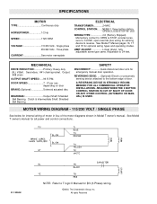
...on the 3-button station will signal when the set an internal Maintenance Cycle Counter. For specifications, service, or replacement part requirements, use this addendum. ADDENDUM MODEL APT LOGIC CONTROL (VER. 2.0) INDUSTRIAL DUTY DOOR OPERATOR LOGIC L CONTROL FACTORY SET C2 Wiring See pages 13 & 14 for all mounting and wiring instructions.... requires immediate service. 41B6 LISTED DOOR OPERATOR This addendum is to be used in lieu of those include with T manual 01-17278. APT specifications and component identification are included with this addendum in conjunction with the manual.
...on the 3-button station will signal when the set an internal Maintenance Cycle Counter. For specifications, service, or replacement part requirements, use this addendum. ADDENDUM MODEL APT LOGIC CONTROL (VER. 2.0) INDUSTRIAL DUTY DOOR OPERATOR LOGIC L CONTROL FACTORY SET C2 Wiring See pages 13 & 14 for all mounting and wiring instructions.... requires immediate service. 41B6 LISTED DOOR OPERATOR This addendum is to be used in lieu of those include with T manual 01-17278. APT specifications and component identification are included with this addendum in conjunction with the manual.

APT LOGIC VERSION 2 Manual
Page 2
... Motor Kit (BAPT5023L2 & BAPT5043L2) 1 3 K-BAPT5011 Electrical Box Kit (Model BAPT5011L2) 1 K-BAPT5021 Electrical Box Kit (Model BAPT5021L2) 1 K-BAPT5023 Electrical Box Kit (Model BAPT5023L2) 1 K-BAPT5043 Electrical Box Kit (Model BAPT5043L2) 1 4 Varies Track 1 K72-13059 OUTPUT SHAFT KIT ITEM PART # DESCRIPTION O1 11-10124 APT Output Shaft O2 12-10331 Flange Ball Bearing, 3/4" ID O3 15...Pin, 1/4" Dia x 2" Long QTY 1 2 1 1 1 1 1 INDIVIDUAL ASSEMBLY SERVICE KITS ITEM PART # DESCRIPTION H6 K75-10387 Slider Assembly H7 K75-10388 Chain Tensioner Assembly 2 MODEL APT -
... Motor Kit (BAPT5023L2 & BAPT5043L2) 1 3 K-BAPT5011 Electrical Box Kit (Model BAPT5011L2) 1 K-BAPT5021 Electrical Box Kit (Model BAPT5021L2) 1 K-BAPT5023 Electrical Box Kit (Model BAPT5023L2) 1 K-BAPT5043 Electrical Box Kit (Model BAPT5043L2) 1 4 Varies Track 1 K72-13059 OUTPUT SHAFT KIT ITEM PART # DESCRIPTION O1 11-10124 APT Output Shaft O2 12-10331 Flange Ball Bearing, 3/4" ID O3 15...Pin, 1/4" Dia x 2" Long QTY 1 2 1 1 1 1 1 INDIVIDUAL ASSEMBLY SERVICE KITS ITEM PART # DESCRIPTION H6 K75-10387 Slider Assembly H7 K75-10388 Chain Tensioner Assembly 2 MODEL APT -
APT LOGIC VERSION 2 Manual
Page 4
... W/ LED WIRING TYPE C2 (Factory Shipped) Momentary contact to OPEN & STOP, constant pressure to CLOSE, open override plus wiring for internal wiring of motor in Model T owner's manual. REQUIRED WHEN THE 3 BUTTON CONTROL STATION IS OUT OF SIGHT OF DOOR OR ANY OTHER CONTROL (AUTOMATIC OR MANUAL) IS USED. All rights... Manual for all power and control connections. 01-10384H NOTE: Refer to the bottom edge of the motor diagrams shown in lieu of door. See Model T Manual pages 16, 17 and 18 for emergency manual door operation. See...
... W/ LED WIRING TYPE C2 (Factory Shipped) Momentary contact to OPEN & STOP, constant pressure to CLOSE, open override plus wiring for internal wiring of motor in Model T owner's manual. REQUIRED WHEN THE 3 BUTTON CONTROL STATION IS OUT OF SIGHT OF DOOR OR ANY OTHER CONTROL (AUTOMATIC OR MANUAL) IS USED. All rights... Manual for all power and control connections. 01-10384H NOTE: Refer to the bottom edge of the motor diagrams shown in lieu of door. See Model T Manual pages 16, 17 and 18 for emergency manual door operation. See...


