Dial Code LC and VF Series Manual
Page 1
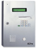
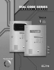
I LT- DIAL CODE SERIES OWNER S MANUAL Telephone entry systems with two line large LC or VF displays with B U I N surge suppression VISIT US ON THE WEB www.chamberlain.com
I LT- DIAL CODE SERIES OWNER S MANUAL Telephone entry systems with two line large LC or VF displays with B U I N surge suppression VISIT US ON THE WEB www.chamberlain.com

Dial Code LC and VF Series Manual
Page 2
... Viewing Software Version 20 Warning and Precautions 21 Programming the Processor 22 Selecting Program Mode 23 Resident Information 24 Transmitter / Card Programming 25 Area Codes 26 Utility Codes 27 Password 28 Clock / Timer 29-31 Strike Time 32 Talk Time 32 Greeting 33 Volume Adjustment 33 Back-Up Memory 34 Error Messages...
... Viewing Software Version 20 Warning and Precautions 21 Programming the Processor 22 Selecting Program Mode 23 Resident Information 24 Transmitter / Card Programming 25 Area Codes 26 Utility Codes 27 Password 28 Clock / Timer 29-31 Strike Time 32 Talk Time 32 Greeting 33 Volume Adjustment 33 Back-Up Memory 34 Error Messages...
Dial Code LC and VF Series Manual
Page 3
... PCMCIA memory card • Two (2) slots for PCMCIA memory cards. • Double box with built-in speaker during dialing. • Postal lock capability with leap year & daylight savings compensation. • 2 programmable 7-day timers for door ... - Relay ports - Telephone line port - Talk time is rain resistant. • Power Input: 12 Vac, 40VA UL listed transformer(provided). • Operating Environment: - Battery enables dial out, program, & display. - Relative Humidity: 5% - 95% non-condensing. • Dimensions: 11 1/4" W X 16 7/16" H X 4 1/8" D • Shipping Weight: ...
... PCMCIA memory card • Two (2) slots for PCMCIA memory cards. • Double box with built-in speaker during dialing. • Postal lock capability with leap year & daylight savings compensation. • 2 programmable 7-day timers for door ... - Relay ports - Telephone line port - Talk time is rain resistant. • Power Input: 12 Vac, 40VA UL listed transformer(provided). • Operating Environment: - Battery enables dial out, program, & display. - Relative Humidity: 5% - 95% non-condensing. • Dimensions: 11 1/4" W X 16 7/16" H X 4 1/8" D • Shipping Weight: ...

Dial Code LC and VF Series Manual
Page 4
... name is found, enter the corresponding 3-digit code. Vehicular Gate By pressing or dialing the number "9" on their digital or rotary phone, Fairbanks, George CODE: 012 (fig c.) Fairbanks, George DIALING! Door or Pedestrian Gate By pressing or dialing the number "5" on their digital or rotary phone...operating, the Telephone Entry System will open the vehicular entrance gate. The system will dial the number assigned to the resident code entered. (fig d.) After connecting, the screen will open the door or pedestrian gate. CODE: 012 (fig d.) TIME TO TALK> 17 SEC ___ (fig e.) Entry 2 ...
... name is found, enter the corresponding 3-digit code. Vehicular Gate By pressing or dialing the number "9" on their digital or rotary phone, Fairbanks, George CODE: 012 (fig c.) Fairbanks, George DIALING! Door or Pedestrian Gate By pressing or dialing the number "5" on their digital or rotary phone...operating, the Telephone Entry System will open the vehicular entrance gate. The system will dial the number assigned to the resident code entered. (fig d.) After connecting, the screen will open the door or pedestrian gate. CODE: 012 (fig d.) TIME TO TALK> 17 SEC ___ (fig e.) Entry 2 ...

Dial Code LC and VF Series Manual
Page 5
... screen will display "Access Granted" (fig c.) and access will be (fig d.) allowed (fig d.) EXAMPLE - UTILITY CODE 8716 = 8 71 6 SCREEN SAVER MODE (VF ONLY) If the VF Dial Code System is entered, the system will go into sleep mode. The screen will continue to display the scrolling message "Press...it will inform the user of the invalid entry (fig b.) The resident can then re-enter their keycode. * INVALID ENTRY * Invalid 6-Digit Code (fig b.) EXAMPLE - To use the keycode assigned, the resident must first press the key TWICE and then enter their keycode. To access ...
... screen will display "Access Granted" (fig c.) and access will be (fig d.) allowed (fig d.) EXAMPLE - UTILITY CODE 8716 = 8 71 6 SCREEN SAVER MODE (VF ONLY) If the VF Dial Code System is entered, the system will go into sleep mode. The screen will continue to display the scrolling message "Press...it will inform the user of the invalid entry (fig b.) The resident can then re-enter their keycode. * INVALID ENTRY * Invalid 6-Digit Code (fig b.) EXAMPLE - To use the keycode assigned, the resident must first press the key TWICE and then enter their keycode. To access ...

Dial Code LC and VF Series Manual
Page 6
LC ENTRY PHONE FEATURES (INSIDE) Mounting Holes (4) Processor Key Release / Lock LC Display Processor Unit Dialing Keys Programming Keys Parallel Port Memory Card Memory Card Slot Memory Card Release Buttons Processor Power Switch Microphone POWER GATE RELAY DOOR RELAY Surge Suppressor Terminal Board Postal Lock Setup Display Window Stainless Steel Door Key Lock External Keypad External Speaker All components and specifications are subject to change without notice. LC/VF Page 5
LC ENTRY PHONE FEATURES (INSIDE) Mounting Holes (4) Processor Key Release / Lock LC Display Processor Unit Dialing Keys Programming Keys Parallel Port Memory Card Memory Card Slot Memory Card Release Buttons Processor Power Switch Microphone POWER GATE RELAY DOOR RELAY Surge Suppressor Terminal Board Postal Lock Setup Display Window Stainless Steel Door Key Lock External Keypad External Speaker All components and specifications are subject to change without notice. LC/VF Page 5

Dial Code LC and VF Series Manual
Page 7
... wants 11 to 5 help guide the user. 4 EXTERNAL SPEAKER 5 DISPLAY WINDOW - Residents and utility personnel use this key with their key code to change without notice. All components and specifications are subject to open gate. 10 HANG-UP KEY - LC/VF Page 6 Lights up .... Heavy-duty and weather resistant. Scrolls through names in 10 alphabetical order on screen. 9 UNLOCK KEY - Heavy-duty, 3/8" thick protective lens. 6 6 DIALING KEYS LIGHT - Used to access the Processor. 3 HELP KEY - LC ENTRY PHONE FEATURES (OUTSIDE) 1 EXTERNAL MICROPHONE 1 2 KEY LOCK - Opens the Processor...
... wants 11 to 5 help guide the user. 4 EXTERNAL SPEAKER 5 DISPLAY WINDOW - Residents and utility personnel use this key with their key code to change without notice. All components and specifications are subject to open gate. 10 HANG-UP KEY - LC/VF Page 6 Lights up .... Heavy-duty and weather resistant. Scrolls through names in 10 alphabetical order on screen. 9 UNLOCK KEY - Heavy-duty, 3/8" thick protective lens. 6 6 DIALING KEYS LIGHT - Used to access the Processor. 3 HELP KEY - LC ENTRY PHONE FEATURES (OUTSIDE) 1 EXTERNAL MICROPHONE 1 2 KEY LOCK - Opens the Processor...

Dial Code LC and VF Series Manual
Page 8
LC/VF Page 7 VF ENTRY PHONE FEATURES (INSIDE) Mounting Holes (4) Processor Key Release / Lock VF Display Processor Unit Dialing Keys Programming Keys Parallel Port Memory Card Memory Card Slot Memory Card Release Buttons Processor Power Switch Microphone Display Hood Display Window Stainless Steel Door Key Lock External Keypad POWER GATE RELAY DOOR RELAY Surge Suppressor Terminal Board Postal Lock Setup External Speaker All components and specifications are subject to change without notice.
LC/VF Page 7 VF ENTRY PHONE FEATURES (INSIDE) Mounting Holes (4) Processor Key Release / Lock VF Display Processor Unit Dialing Keys Programming Keys Parallel Port Memory Card Memory Card Slot Memory Card Release Buttons Processor Power Switch Microphone Display Hood Display Window Stainless Steel Door Key Lock External Keypad POWER GATE RELAY DOOR RELAY Surge Suppressor Terminal Board Postal Lock Setup External Speaker All components and specifications are subject to change without notice.

Dial Code LC and VF Series Manual
Page 9
...weather resistant. Residents and utility personnel use this key with their key code 12 to access the Processor. 6 3 HELP KEY - With digital voice messages to dial 11 residents / keycodes 9 SCROLL KEYS - Reduces reflections and direct sunlight. 8 2 7 DIALING KEYS LIGHT - Used to 5 help guide the user. 4 EXTERNAL...Pressed when user wants 13 to change without notice. All components and specifications are subject to hang up 9 dialing keys for easy visibility. 3 10 8 PHONE DIALING KEYS - VF ENTRY PHONE FEATURES (OUTSIDE) 1 EXTERNAL MICROPHONE 1 2 KEY LOCK -
...weather resistant. Residents and utility personnel use this key with their key code 12 to access the Processor. 6 3 HELP KEY - With digital voice messages to dial 11 residents / keycodes 9 SCROLL KEYS - Reduces reflections and direct sunlight. 8 2 7 DIALING KEYS LIGHT - Used to 5 help guide the user. 4 EXTERNAL...Pressed when user wants 13 to change without notice. All components and specifications are subject to hang up 9 dialing keys for easy visibility. 3 10 8 PHONE DIALING KEYS - VF ENTRY PHONE FEATURES (OUTSIDE) 1 EXTERNAL MICROPHONE 1 2 KEY LOCK -

Dial Code LC and VF Series Manual
Page 10
Press this key to go back to surge suppressor terminal board. 17 INPUT/OUTPUT CONNECTOR - Q W E R T Y U I O P 12 SHIFT A S D F G H J K L 13 SPACE BAR Z X C V B N M ' BACK SPACE 15 13 HELP KEY - Used for RS485 devices. 3 POWER ON/OFF SWITCH 4 CARD RELEASE BUTTONS - Holds RF Communicator Card or Backup Memory. 7 LCD TWO LINE, LARGE LIQUID CRYSTAL DISPLAY OR VF SUPER BRIGHT VACUUM FLUORESCENT DISPLAY SCREEN- Registers information into memory after it 11 ERASE EXIT PROGRAM ENTER HELP 0 is typed. LC/VF Page 9 Card for the Icon26 only. 19 18 ...
Press this key to go back to surge suppressor terminal board. 17 INPUT/OUTPUT CONNECTOR - Q W E R T Y U I O P 12 SHIFT A S D F G H J K L 13 SPACE BAR Z X C V B N M ' BACK SPACE 15 13 HELP KEY - Used for RS485 devices. 3 POWER ON/OFF SWITCH 4 CARD RELEASE BUTTONS - Holds RF Communicator Card or Backup Memory. 7 LCD TWO LINE, LARGE LIQUID CRYSTAL DISPLAY OR VF SUPER BRIGHT VACUUM FLUORESCENT DISPLAY SCREEN- Registers information into memory after it 11 ERASE EXIT PROGRAM ENTER HELP 0 is typed. LC/VF Page 9 Card for the Icon26 only. 19 18 ...
Dial Code LC and VF Series Manual
Page 11
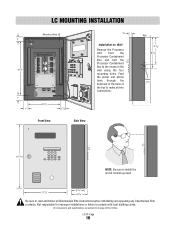
... unit at normal eye level 11 1/4 " 3 1/4" 41/8 " Be sure to change without notice. Not responsible for improper installations or failure to comply with local building codes. LC MOUNTING INSTALLATION Mounting Holes (4) 1" 14 1/2" Wire Knock Outs TEL LINE RS-485 (1 RS-485 (2 RS-485 (3 RS-485 (4 TP RING +) -) GND (+) -) GND (+) -) GND (+) -) GND...
... unit at normal eye level 11 1/4 " 3 1/4" 41/8 " Be sure to change without notice. Not responsible for improper installations or failure to comply with local building codes. LC MOUNTING INSTALLATION Mounting Holes (4) 1" 14 1/2" Wire Knock Outs TEL LINE RS-485 (1 RS-485 (2 RS-485 (3 RS-485 (4 TP RING +) -) GND (+) -) GND (+) -) GND (+) -) GND...

Dial Code LC and VF Series Manual
Page 12
... If unit is not grounded lightning damage wi l occur Please refer to he owners manual for improper installations or failure to comply with local building codes. LC/VF Page 11
... If unit is not grounded lightning damage wi l occur Please refer to he owners manual for improper installations or failure to comply with local building codes. LC/VF Page 11

Dial Code LC and VF Series Manual
Page 13
Activates gate relay using gate strike time. 8 CHASSIS GROUND: Entry Phone MUST be connected to the ground rod. LC/VF Page 12 If unit is activated for 5 seconds, allowing recording of remote security devices. 4 DOOR RELAY: For allowing access through pedestrian gate or door. 5 GATE RELAY: For use with gate operator to the owners manual for proper grounding instructions. Each time access is granted, the VCR Relay is not grounded, lightning damage will occur. DESCRIPTION OF SURGE SUPPRESSION TERMINAL BOARD 1 TEL LINE RS485 (1) 3 RS485 (2) 3 RS485 (3) 3 RS485 (4) 3 TIP RING (+) ...
Activates gate relay using gate strike time. 8 CHASSIS GROUND: Entry Phone MUST be connected to the ground rod. LC/VF Page 12 If unit is activated for 5 seconds, allowing recording of remote security devices. 4 DOOR RELAY: For allowing access through pedestrian gate or door. 5 GATE RELAY: For use with gate operator to the owners manual for proper grounding instructions. Each time access is granted, the VCR Relay is not grounded, lightning damage will occur. DESCRIPTION OF SURGE SUPPRESSION TERMINAL BOARD 1 TEL LINE RS485 (1) 3 RS485 (2) 3 RS485 (3) 3 RS485 (4) 3 TIP RING (+) ...

Dial Code LC and VF Series Manual
Page 14
The provided "chassis ground" wire must be connected to the ground rod. GROUNDING THE UNIT Chassis Ground TEL L NE RS 485 (1) RS 485 (2) RS 485 (3) RS 485 (4) TIP RING (+) () GND (+) () GND (+) () GND (+) () GND 12V AC/DC POWER INPUT DOOR NO DOOR NC DOOR C GATE NO GATE NC GATE C VCR NO VCR C GND INPUT CHASSIS GROUND DOOR RELAY GATE RELAY VCR RELAY POSTAL/EXIT SW INPUT It is MANDATORY that this unit is properly grounded. The provided "chassis ground" wire must be connected to the ground rod. eliteentryphone com MADE N USA POWER GATE RELAY DOOR RELAY Ground Rod Refer to...
The provided "chassis ground" wire must be connected to the ground rod. GROUNDING THE UNIT Chassis Ground TEL L NE RS 485 (1) RS 485 (2) RS 485 (3) RS 485 (4) TIP RING (+) () GND (+) () GND (+) () GND (+) () GND 12V AC/DC POWER INPUT DOOR NO DOOR NC DOOR C GATE NO GATE NC GATE C VCR NO VCR C GND INPUT CHASSIS GROUND DOOR RELAY GATE RELAY VCR RELAY POSTAL/EXIT SW INPUT It is MANDATORY that this unit is properly grounded. The provided "chassis ground" wire must be connected to the ground rod. eliteentryphone com MADE N USA POWER GATE RELAY DOOR RELAY Ground Rod Refer to...

Dial Code LC and VF Series Manual
Page 15
...Telephone Entry System (TES). Never splice two wires for correct grounding materials and installation procedures. For the correct depth consult the local code Chamberlain Elite is not responsible for improper installation or failure to comply with a single wire length. Contact the building inspector's office in... an electrical static discharge or a near lightning strike, a path from the TES System. For the correct wire gauge, consult the local code The ground wire must be a single, whole piece of a direct lightning strike, proper grounding can protect the Telehone Entry System in the...
...Telephone Entry System (TES). Never splice two wires for correct grounding materials and installation procedures. For the correct depth consult the local code Chamberlain Elite is not responsible for improper installation or failure to comply with a single wire length. Contact the building inspector's office in... an electrical static discharge or a near lightning strike, a path from the TES System. For the correct wire gauge, consult the local code The ground wire must be a single, whole piece of a direct lightning strike, proper grounding can protect the Telehone Entry System in the...

Dial Code LC and VF Series Manual
Page 16
... Wiring. Entry 2 Door Relay Terminal Connection Pedestrian Gate Maglock Conduit Conduit Master Gate Operator (Strike Open Input) Access Door Solenoid OR OR Entry Door Maglock Dial Dial Connect two wires to the secondary gate or door. The door relay will be activated by either pressing 5 on the resident's phone, entering a utility or...
... Wiring. Entry 2 Door Relay Terminal Connection Pedestrian Gate Maglock Conduit Conduit Master Gate Operator (Strike Open Input) Access Door Solenoid OR OR Entry Door Maglock Dial Dial Connect two wires to the secondary gate or door. The door relay will be activated by either pressing 5 on the resident's phone, entering a utility or...

Dial Code LC and VF Series Manual
Page 17
... GATE-C VCR-NO VCR-C CHASSIS GROUND GND INPUT DOOR RELAY GATE RELAY VCR RELAY POSTAL/EXIT SW INPUT It is MANDATORY that polarity or color coding is not required. Ensure that full extension of the sliding bolt will occur. When the postal lock is engaged, the system's gate relay is activated...
... GATE-C VCR-NO VCR-C CHASSIS GROUND GND INPUT DOOR RELAY GATE RELAY VCR RELAY POSTAL/EXIT SW INPUT It is MANDATORY that polarity or color coding is not required. Ensure that full extension of the sliding bolt will occur. When the postal lock is engaged, the system's gate relay is activated...
Dial Code LC and VF Series Manual
Page 18
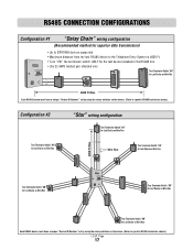
RS485 CONNECTION CONFIGURATIONS Configuration #1 "Daisy Chain" wiring configuration (Recommended method for superior data transmission) • Up to 31 RS485 devices supported • Maximum distance from the last RS485 device to the Telephone Entry System is 4000 Ft. • Turn "ON" the terminator switch ONLY for the last device installed in the RS485 line. • Use 22 AWG twisted pair shielded wire Turn Terminator Switch "ON" for Last Device on Wire Run 4000 Ft Max. LC/VF Page 17 Configuration #2 Turn Terminator Switch "ON" for Last Device on Wire Run "Star" wiring ...
RS485 CONNECTION CONFIGURATIONS Configuration #1 "Daisy Chain" wiring configuration (Recommended method for superior data transmission) • Up to 31 RS485 devices supported • Maximum distance from the last RS485 device to the Telephone Entry System is 4000 Ft. • Turn "ON" the terminator switch ONLY for the last device installed in the RS485 line. • Use 22 AWG twisted pair shielded wire Turn Terminator Switch "ON" for Last Device on Wire Run 4000 Ft Max. LC/VF Page 17 Configuration #2 Turn Terminator Switch "ON" for Last Device on Wire Run "Star" wiring ...
Dial Code LC and VF Series Manual
Page 19
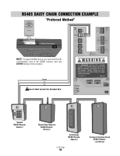
If unit is properly grounded. Please refer to the ground rod. eliteentryphone.com MADE IN USA POWER GATE RELAY DOOR RELAY Keypad RS485 Remote Device 1 Stand-Alone Receiver RS485 Remote Device 2 Card Reader RS485 Remote Device 3 LC/VF Page 18 Universal Interface Board RS485 Remote Last Device The provided "chassis ground" wire must insert the RF communicator card in the RS485 memory card slot BEFORE turning on the processor. RS485 DAISY CHAIN CONNECTION EXAMPLE "Preferred Method" Remote Access RS485 COMMUNICATOR CARD capacity Elite Entry Phone Main Me Card Slot RS485 Memory ...
If unit is properly grounded. Please refer to the ground rod. eliteentryphone.com MADE IN USA POWER GATE RELAY DOOR RELAY Keypad RS485 Remote Device 1 Stand-Alone Receiver RS485 Remote Device 2 Card Reader RS485 Remote Device 3 LC/VF Page 18 Universal Interface Board RS485 Remote Last Device The provided "chassis ground" wire must insert the RF communicator card in the RS485 memory card slot BEFORE turning on the processor. RS485 DAISY CHAIN CONNECTION EXAMPLE "Preferred Method" Remote Access RS485 COMMUNICATOR CARD capacity Elite Entry Phone Main Me Card Slot RS485 Memory ...

Dial Code LC and VF Series Manual
Page 20
eliteentryphone.com MADE IN USA POWER GTAE RELAY DOOR RELAY Card Reader RS485 Remote Device 4 LC/VF Page 19 (+) (-) Ground Please refer to the ground rod. The provided "chassis ground" wire must insert the RF communicator card in the RS485 memory card slot BEFORE turning on the processor. RS485 STAR CONNECTION EXAMPLE Remote Access RS485 COMMUNICATOR CARD capacity Elite Entry Phone Main M ard Slot RS485 Memory Card Slot Use 22 AWG Twisted Pair Shielded Wire Keypad RS485 Remote Device 1 (+) (-) Ground RS485 Card Release Button NOTE: To support RS485 devices you must ...
eliteentryphone.com MADE IN USA POWER GTAE RELAY DOOR RELAY Card Reader RS485 Remote Device 4 LC/VF Page 19 (+) (-) Ground Please refer to the ground rod. The provided "chassis ground" wire must insert the RF communicator card in the RS485 memory card slot BEFORE turning on the processor. RS485 STAR CONNECTION EXAMPLE Remote Access RS485 COMMUNICATOR CARD capacity Elite Entry Phone Main M ard Slot RS485 Memory Card Slot Use 22 AWG Twisted Pair Shielded Wire Keypad RS485 Remote Device 1 (+) (-) Ground RS485 Card Release Button NOTE: To support RS485 devices you must ...