GT LOGIC VERSION 2 Manual
Page 1
An LED on the 3-button station will signal when the set an internal Maintenance Cycle Counter. OWNER'S MANUAL MODEL GT LOGIC CONTROL (VER. 2.0) INDUSTRIAL DUTY DOOR OPERATOR LOGIC LCONTROL FACTORY SET C2 Wiring See pages 14 and 15 for other wiring configurations PATENT PENDING The Maintenance Alert System TM allows the installer to set number of cycles is reached or when the opener requires immediate service. 2 YEAR WARRANTY Serial # (located on electrical box cover) Installation Date Wiring Type NOT FOR RESIDENTIAL USE 41B6 LISTED DOOR OPERATOR
An LED on the 3-button station will signal when the set an internal Maintenance Cycle Counter. OWNER'S MANUAL MODEL GT LOGIC CONTROL (VER. 2.0) INDUSTRIAL DUTY DOOR OPERATOR LOGIC LCONTROL FACTORY SET C2 Wiring See pages 14 and 15 for other wiring configurations PATENT PENDING The Maintenance Alert System TM allows the installer to set number of cycles is reached or when the opener requires immediate service. 2 YEAR WARRANTY Serial # (located on electrical box cover) Installation Date Wiring Type NOT FOR RESIDENTIAL USE 41B6 LISTED DOOR OPERATOR

GT LOGIC VERSION 2 Manual
Page 9
Any commercial type LiftMaster brand receiver may be mounted to the captive terminal block in the electrical box enclosure marked with the label shown below . 1 SBC SINGLE BUTTON CONTROL 2 2 ... WIRING CONNECTIONS 1. IMPORTANT: THIS UNIT MUST BE PROPERLY GROUNDED. FAILURE TO PROPERLY GROUND THIS UNIT COULD RESULT IN ELECTRIC SHOCK AND SERIOUS INJURY. 3. On all models with connections for improper wiring at the control station or between operator and control station. MOUNTING INSTRUCTIONS 1. Mount WARNING NOTICE beside or below ). TB2 1 SBC...
Any commercial type LiftMaster brand receiver may be mounted to the captive terminal block in the electrical box enclosure marked with the label shown below . 1 SBC SINGLE BUTTON CONTROL 2 2 ... WIRING CONNECTIONS 1. IMPORTANT: THIS UNIT MUST BE PROPERLY GROUNDED. FAILURE TO PROPERLY GROUND THIS UNIT COULD RESULT IN ELECTRIC SHOCK AND SERIOUS INJURY. 3. On all models with connections for improper wiring at the control station or between operator and control station. MOUNTING INSTRUCTIONS 1. Mount WARNING NOTICE beside or below ). TB2 1 SBC...

GT LOGIC VERSION 2 Manual
Page 22
... NUMBER - 1-800-528-2806 MONDAY THROUGH FRIDAY 5 AM TO 6 PM (MST) SATURDAY 7 AM TO 3:30 PM (MST) WWW.LIFTMASTER.COM WHEN ORDERING REPAIR PARTS PLEASE SUPPLY THE FOLLOWING INFORMATION: PART NUMBER DESCRIPTION MODEL NUMBER 22 ITEM PROCEDURE EVERY 3 MONTHS OR 5,000 CYCLES Drive Chain Check for continuous operation. n Do not lubricate motor...
... NUMBER - 1-800-528-2806 MONDAY THROUGH FRIDAY 5 AM TO 6 PM (MST) SATURDAY 7 AM TO 3:30 PM (MST) WWW.LIFTMASTER.COM WHEN ORDERING REPAIR PARTS PLEASE SUPPLY THE FOLLOWING INFORMATION: PART NUMBER DESCRIPTION MODEL NUMBER 22 ITEM PROCEDURE EVERY 3 MONTHS OR 5,000 CYCLES Drive Chain Check for continuous operation. n Do not lubricate motor...

GT LOGIC VERSION 2 Manual
Page 24
...BOX LOGIC CONTROL (VER. 2.0) Below are replacement kits available for all repair part ordering information. Refer to the model number of your operator. DESCRIPTION 21-14182 Transformer, 115 Volts 3 21-5460 Transformer, 460 Volts 21-5575 ...K20-1150C2 K20-3150C4 K20-5115C6 Models GT5011M, GT5021M Models GT5023M, GT5043M, GT5038M Models GT5025M Models GT7511M, GT7521M Models GT7523M, GT7543M, GT7538M Model GT7525M Models GT1011M, GT1021M Models GT1023M, GT1043M, GT1038M Model GT1025M Models GT1511M, GT1521M Models GT1523M, GT1543M, GT1538M Model GT1525M Shaft Assemblies K75-12858 ...
...BOX LOGIC CONTROL (VER. 2.0) Below are replacement kits available for all repair part ordering information. Refer to the model number of your operator. DESCRIPTION 21-14182 Transformer, 115 Volts 3 21-5460 Transformer, 460 Volts 21-5575 ...K20-1150C2 K20-3150C4 K20-5115C6 Models GT5011M, GT5021M Models GT5023M, GT5043M, GT5038M Models GT5025M Models GT7511M, GT7521M Models GT7523M, GT7543M, GT7538M Model GT7525M Models GT1011M, GT1021M Models GT1023M, GT1043M, GT1038M Model GT1025M Models GT1511M, GT1521M Models GT1523M, GT1543M, GT1538M Model GT1525M Shaft Assemblies K75-12858 ...

GT LOGIC VERSION 2 Manual
Page 25
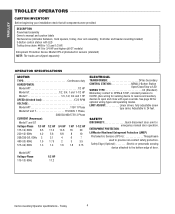
MODEL GT 25 S4 D8 D5 S6 D2 S5 D7 D9 D10 7 2 S1 S2 S3 D4 D1 S7 H4 H6 H8 H3 H5 10 DRIVE CHAIN TRACK S5 S6 S4 D2 D9 H7 D3 H2 H1 D10 D8 D6 6 5 B14 4 B2 B7 B15 B10 C1 C2 C4 C5 B15 B14 B8 B16 B13 B6 B5 B12 B3 C4 B9 B4 9 C2 B1 C3 C6 C3 B11 C7 3 1 8 ILLUSTRATED PARTS -
MODEL GT 25 S4 D8 D5 S6 D2 S5 D7 D9 D10 7 2 S1 S2 S3 D4 D1 S7 H4 H6 H8 H3 H5 10 DRIVE CHAIN TRACK S5 S6 S4 D2 D9 H7 D3 H2 H1 D10 D8 D6 6 5 B14 4 B2 B7 B15 B10 C1 C2 C4 C5 B15 B14 B8 B16 B13 B6 B5 B12 B3 C4 B9 B4 9 C2 B1 C3 C6 C3 B11 C7 3 1 8 ILLUSTRATED PARTS -

GT LOGIC VERSION 2 Manual
Page 26
... Pin, 1/8" x 1-3/4" Zinc Plate Push on Fastener, 5/8" Int. If optional modifications and/or accessories are included with your operator. Individual components of individual components. MODEL GT LOGIC CONTROL (VER. 2.0) Refer to the parts lists below for replacement kits available for Brake Assembly Brake Stud Spring, Compression x .875" Long Chain, #48..., 575V Spacer, .20 I.D. BRAKE ASSEMBLY KITS KIT PART # 71-B120 71-B240 71-B575 FOR OPERATOR(S) 115 Volt Models 230-460 Volt Models 575 Volt Models ITEM B1 B2 B3 B4 B5 B6 B7 B8 B9 B10 B11 B12 B13 B14 B15 B16 PART # 07-10179 10-10187...
... Pin, 1/8" x 1-3/4" Zinc Plate Push on Fastener, 5/8" Int. If optional modifications and/or accessories are included with your operator. Individual components of individual components. MODEL GT LOGIC CONTROL (VER. 2.0) Refer to the parts lists below for replacement kits available for Brake Assembly Brake Stud Spring, Compression x .875" Long Chain, #48..., 575V Spacer, .20 I.D. BRAKE ASSEMBLY KITS KIT PART # 71-B120 71-B240 71-B575 FOR OPERATOR(S) 115 Volt Models 230-460 Volt Models 575 Volt Models ITEM B1 B2 B3 B4 B5 B6 B7 B8 B9 B10 B11 B12 B13 B14 B15 B16 PART # 07-10179 10-10187...

GT-LOGIC 3 Manual
Page 13
... If the door moves in the wrong direction and or the limits move the motor direction jumper located on the DJ and DH models. EXTERNAL RADIO WIRING CONNECTIONS On all control wires through the conduit hole in receiver, remove or disconnect the coaxial cable from the center... AC 14 24 VOLT AC 24V AC 13 24 VOLT AC TIMER DEFEAT 12 TIMER DEFEAT CMN 11 COMMON AVERMASTIS10 SMEAINMTENEANNCETALERT SYSTEM EYES 9 PHOTO EYES (LiftMaster Only) ATTEDEGEN8TRIOEVENRSE OPEN 7 OPEN CLOSE 6 CLOSE STOP 5 STOP CMN 4 COMMON 3 INTERLOCK 2 INTERLOCK SBC 1 SINGLE BUTTON CONTROL ADVERTENCIA PRECAUCIÓNOR ...
... If the door moves in the wrong direction and or the limits move the motor direction jumper located on the DJ and DH models. EXTERNAL RADIO WIRING CONNECTIONS On all control wires through the conduit hole in receiver, remove or disconnect the coaxial cable from the center... AC 14 24 VOLT AC 24V AC 13 24 VOLT AC TIMER DEFEAT 12 TIMER DEFEAT CMN 11 COMMON AVERMASTIS10 SMEAINMTENEANNCETALERT SYSTEM EYES 9 PHOTO EYES (LiftMaster Only) ATTEDEGEN8TRIOEVENRSE OPEN 7 OPEN CLOSE 6 CLOSE STOP 5 STOP CMN 4 COMMON 3 INTERLOCK 2 INTERLOCK SBC 1 SINGLE BUTTON CONTROL ADVERTENCIA PRECAUCIÓNOR ...

GT-LOGIC 3 Manual
Page 15
...C (YE) +24 VAC -24 VAC COIL (GY) (WH) COM OPEN L/S NO NC (RD) (PU) (WH) COM NO CLOSE L/S NC NOTE: Lock Sensor is provided on Models DJ and DH only, red wire from main harness connects to NC on Bypass L/S and to NC on Lock Sensor switch. LOGIC (VER. 3.0) 1 PHASE WIRING... DIAGRAM 115V MOTOR CONNECTION 230V MOTOR CONNECTION NOTE: Gray (GY) and purple (PU) motor wires are reversed for H and HJ right hand models and all GH and J models. CPS-L & CPS-LN4 Sensing Edge Hoist Interlock When Present TMR DEF SWITCH (YE) (BL) Maintenance Alert LED (RD) (WH) Open Close Stop ...
...C (YE) +24 VAC -24 VAC COIL (GY) (WH) COM OPEN L/S NO NC (RD) (PU) (WH) COM NO CLOSE L/S NC NOTE: Lock Sensor is provided on Models DJ and DH only, red wire from main harness connects to NC on Bypass L/S and to NC on Lock Sensor switch. LOGIC (VER. 3.0) 1 PHASE WIRING... DIAGRAM 115V MOTOR CONNECTION 230V MOTOR CONNECTION NOTE: Gray (GY) and purple (PU) motor wires are reversed for H and HJ right hand models and all GH and J models. CPS-L & CPS-LN4 Sensing Edge Hoist Interlock When Present TMR DEF SWITCH (YE) (BL) Maintenance Alert LED (RD) (WH) Open Close Stop ...

GT-LOGIC 3 Manual
Page 16
...) NO COM C COIL 0 B1 4 8 (WH) 2 6 (GY) (WH) COM OPEN L/S NO NC (RD) (PU) (WH) COM NO CLOSE L/S NC (WH) NOTE: Lock Sensor is provided on Models DJ and DH only, red wire from main harness connects to NC on Bypass L/S and to NC on COM BYPASS NO L/S NC (RD) Lock Sensor...) 208/230V MOTOR CONNECTION 460V MOTOR CONNECTION 575V MOTOR CONNECTION NOTE: Gray (GY) and purple (PU) motor wires are reversed for H and HJ right hand models and all GH and...
...) NO COM C COIL 0 B1 4 8 (WH) 2 6 (GY) (WH) COM OPEN L/S NO NC (RD) (PU) (WH) COM NO CLOSE L/S NC (WH) NOTE: Lock Sensor is provided on Models DJ and DH only, red wire from main harness connects to NC on Bypass L/S and to NC on COM BYPASS NO L/S NC (RD) Lock Sensor...) 208/230V MOTOR CONNECTION 460V MOTOR CONNECTION 575V MOTOR CONNECTION NOTE: Gray (GY) and purple (PU) motor wires are reversed for H and HJ right hand models and all GH and...

GT-LOGIC 3 Manual
Page 25
... wiring type. LOSE OPEN RPM Sensor Logic Board MAXIMUM RUN TIMER (MRT) Feature: The operator can learn the time it will vary depending on models GH and GT.) NOTE: This feature is 90 seconds. Benefit: If the operator does not meet its open or close limit within the set time it takes...
... wiring type. LOSE OPEN RPM Sensor Logic Board MAXIMUM RUN TIMER (MRT) Feature: The operator can learn the time it will vary depending on models GH and GT.) NOTE: This feature is 90 seconds. Benefit: If the operator does not meet its open or close limit within the set time it takes...

GT-LOGIC 3 Manual
Page 33
... - (C and D relay) 3 Phase only Relay 24Vdc SPDT - (C relay) 1 Phase only MOV 580V RPM sensor assembly Logic board - prefix to the model number of your unit to kit number below to match model number of your operator. Limit switch kit Complete with : Limit shaft, limit nuts, limit bearings, limit sprocket, interrupter cup, shim...
... - (C and D relay) 3 Phase only Relay 24Vdc SPDT - (C relay) 1 Phase only MOV 580V RPM sensor assembly Logic board - prefix to the model number of your unit to kit number below to match model number of your operator. Limit switch kit Complete with : Limit shaft, limit nuts, limit bearings, limit sprocket, interrupter cup, shim...

GT-LOGIC 3 Manual
Page 35
..., GT7521L3 K20-3075B-4P Motor - models GT7523L3, GT7543L3 K20-3075M-5 Motor - model GT7553L3 K20-1100B-2LPMotor - English 01-19459SP Owner's Manual - K2 K75-10177 Brake hub kit Complete with: Brake hub, set screw, push on fastener. MODEL GT SERVICE KITS ITEM PART # DESCRIPTION K1 71-B120... 71-B240 71-B575 Brake kit - 115 Volt models Brake kit - 230-460 Volt models Brake kit - 575 Volt models Complete with : Idler shaft, bearing, pulley, hex bolt,...
..., GT7521L3 K20-3075B-4P Motor - models GT7523L3, GT7543L3 K20-3075M-5 Motor - model GT7553L3 K20-1100B-2LPMotor - English 01-19459SP Owner's Manual - K2 K75-10177 Brake hub kit Complete with: Brake hub, set screw, push on fastener. MODEL GT SERVICE KITS ITEM PART # DESCRIPTION K1 71-B120... 71-B240 71-B575 Brake kit - 115 Volt models Brake kit - 230-460 Volt models Brake kit - 575 Volt models Complete with : Idler shaft, bearing, pulley, hex bolt,...
GT- Logic 4 Installation Manual
Page 2
...Specifications 4-5 Maximum Door Area 5 Weights and Dimensions 6 ASSEMBLY 7-9 Assemble the Operator (Models T and GT 7 Install the Chain (Models T and GT 8 Assemble the Operator (Model APT 9 TYPICAL INSTALLATION 10-12 Install the Header Bracket 10 Attach the Track to ...LiftMaster Monitored Entrapment Protection (LMEP) Devices 22 ADJUSTMENT 23-24 Limit Adjustment 23 Clutch Adjustment (Belt Drive Model Operators 24 TESTING 25 MANUAL RELEASE 26-27 Emergency Disconnect System Model GT and T 26 Emergency Disconnect System Model APT 26 Emergency Disconnect System Model...
...Specifications 4-5 Maximum Door Area 5 Weights and Dimensions 6 ASSEMBLY 7-9 Assemble the Operator (Models T and GT 7 Install the Chain (Models T and GT 8 Assemble the Operator (Model APT 9 TYPICAL INSTALLATION 10-12 Install the Header Bracket 10 Attach the Track to ...LiftMaster Monitored Entrapment Protection (LMEP) Devices 22 ADJUSTMENT 23-24 Limit Adjustment 23 Clutch Adjustment (Belt Drive Model Operators 24 TESTING 25 MANUAL RELEASE 26-27 Emergency Disconnect System Model GT and T 26 Emergency Disconnect System Model APT 26 Emergency Disconnect System Model...
GT- Logic 4 Installation Manual
Page 4
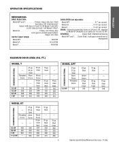
... MOTOR TYPE Continuous duty HORSEPOWER: Model APT 1/2 HP Model GT 1/2, 3/4, 1 and 1-1/2 HP Model T 1/3, 1/2, 3/4 and 1 HP SPEED (At rated load 1725 RPM VOLTAGE Model APT 115V 1 Phase Model GT and T 115/230V 1 Phase, 208/230/460/575V 3 Phase CURRENT (Amperage): Model T and GT Voltage-Phase 1/3 HP 1/2 HP... 3/4 HP and higher (all components were provided. See page 29 for emergency manual door operation. ENTRAPMENT PROTECTION: LiftMaster Monitored Entrapment Protection (LMEP) Photoelectric Sensors (CPS-U Through beam used to the bottom edge of door. Carton inventory...
... MOTOR TYPE Continuous duty HORSEPOWER: Model APT 1/2 HP Model GT 1/2, 3/4, 1 and 1-1/2 HP Model T 1/3, 1/2, 3/4 and 1 HP SPEED (At rated load 1725 RPM VOLTAGE Model APT 115V 1 Phase Model GT and T 115/230V 1 Phase, 208/230/460/575V 3 Phase CURRENT (Amperage): Model T and GT Voltage-Phase 1/3 HP 1/2 HP... 3/4 HP and higher (all components were provided. See page 29 for emergency manual door operation. ENTRAPMENT PROTECTION: LiftMaster Monitored Entrapment Protection (LMEP) Photoelectric Sensors (CPS-U Through beam used to the bottom edge of door. Carton inventory...
GT- Logic 4 Installation Manual
Page 5
...: #41 chain OUTPUT SHAFT SPEED: Model APT 96 RPM Model GT 113.5 RPM Model T 140 RPM DOOR SPEED (not adjustable): Model APT 6-7" per second Model GT 11-12" per second Model T 11-12" per second BRAKE: Solenoid actuated disc brake on 3/4 and 1 HP, standard on Model GT (Available as an option for 1/3 ...640 625 20 ga. Steel --- 20 ga. Steel --- 20 ga. Steel Alum. Steel Insul. 150 --- --- 16 ga. Steel Insul. 100 STANDARD SECTIONAL MODEL GT --- Doors --- --- 1/2 HP 400 350 3/4 HP 560 500 1 HP 625 575 1-1/2 HP --- 625 20 ga. Steel Wood Doors 24 ga. Steel ...
...: #41 chain OUTPUT SHAFT SPEED: Model APT 96 RPM Model GT 113.5 RPM Model T 140 RPM DOOR SPEED (not adjustable): Model APT 6-7" per second Model GT 11-12" per second Model T 11-12" per second BRAKE: Solenoid actuated disc brake on 3/4 and 1 HP, standard on Model GT (Available as an option for 1/3 ...640 625 20 ga. Steel --- 20 ga. Steel --- 20 ga. Steel Alum. Steel Insul. 150 --- --- 16 ga. Steel Insul. 100 STANDARD SECTIONAL MODEL GT --- Doors --- --- 1/2 HP 400 350 3/4 HP 560 500 1 HP 625 575 1-1/2 HP --- 625 20 ga. Steel Wood Doors 24 ga. Steel ...
GT- Logic 4 Installation Manual
Page 6
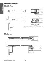
Trolley 6 For Units with Brake add 3-1/2" (Standard on T 1/3 and 1/2 HP models) MODEL GT Hanging Weight: 140 lbs. 4" (10.16 cm) Door Height Plus 4 feet (minimum) 13.05" (33.15 cm) * 17.5" (44.45 cm) 18.5" (46.99 cm) Weights and dimensions - TROLLEY WEIGHTS AND DIMENSIONS MODELS T AND APT Hanging Weight: 80-110 lbs. 4" (10.16 cm) 14" (35.56 cm) *Door Height Plus 4 feet (minimum) Highest Point of Door Travel 11.63" (29.54 cm) *23.43" (59.51 cm) *- Optional on APT, T 3/4 and T 1 HP models;
Trolley 6 For Units with Brake add 3-1/2" (Standard on T 1/3 and 1/2 HP models) MODEL GT Hanging Weight: 140 lbs. 4" (10.16 cm) Door Height Plus 4 feet (minimum) 13.05" (33.15 cm) * 17.5" (44.45 cm) 18.5" (46.99 cm) Weights and dimensions - TROLLEY WEIGHTS AND DIMENSIONS MODELS T AND APT Hanging Weight: 80-110 lbs. 4" (10.16 cm) 14" (35.56 cm) *Door Height Plus 4 feet (minimum) Highest Point of Door Travel 11.63" (29.54 cm) *23.43" (59.51 cm) *- Optional on APT, T 3/4 and T 1 HP models;
GT- Logic 4 Installation Manual
Page 7
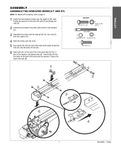
TROLLEY ASSEMBLY ASSEMBLE THE OPERATOR (MODELS T AND GT) NOTE: For Model APT assembly refer to the track with bolts (F) and washers (D). 3 Assemble the trolley with nuts (B). 1 HARDWARE A Bolt 3/8"-16 x 3/4" B Flange Hex Nut 3/8"-16 C Take Up Bolt D E ...
TROLLEY ASSEMBLY ASSEMBLE THE OPERATOR (MODELS T AND GT) NOTE: For Model APT assembly refer to the track with bolts (F) and washers (D). 3 Assemble the trolley with nuts (B). 1 HARDWARE A Bolt 3/8"-16 x 3/4" B Flange Hex Nut 3/8"-16 C Take Up Bolt D E ...
GT- Logic 4 Installation Manual
Page 8
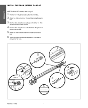
... the chain around the operator drive sprocket. 4 Run the chain along the track to the front of the track. 2 1 2˝ MODEL T 3 MODEL GT 4 5 6 3˝ Assembly - Trolley 8 TROLLEY INSTALL THE CHAIN (MODELS T AND GT) NOTE: For Model APT assembly refer to page 9. 1 Position the trolley 2 inches away from the front idler. 2 Attach the chain to the trolley...
... the chain around the operator drive sprocket. 4 Run the chain along the track to the front of the track. 2 1 2˝ MODEL T 3 MODEL GT 4 5 6 3˝ Assembly - Trolley 8 TROLLEY INSTALL THE CHAIN (MODELS T AND GT) NOTE: For Model APT assembly refer to page 9. 1 Position the trolley 2 inches away from the front idler. 2 Attach the chain to the trolley...
GT- Logic 4 Installation Manual
Page 9
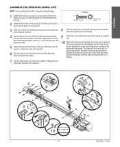
TROLLEY ASSEMBLE THE OPERATOR (MODEL APT) NOTE: If your model is no binding. 7 Run the chain along the track to be loosened or tightened to the free end of the drive link using a master link. ...
TROLLEY ASSEMBLE THE OPERATOR (MODEL APT) NOTE: If your model is no binding. 7 Run the chain along the track to be loosened or tightened to the free end of the drive link using a master link. ...
GT- Logic 4 Installation Manual
Page 13
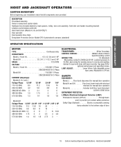
... cams. Adjustable to provide non-contact safety protection. SAFETY DISCONNECT: Model J . . . . .Floor level disconnect for manual door operation Model H and GH Floor level chain hoist with electrical interlock for manual door operation Model HJ Includes both floor level disconnect systems stated above ENTRAPMENT PROTECTION: LiftMaster Monitored Entrapment Protection (LMEP) Photoelectric Sensors (CPS-U Through beam...
... cams. Adjustable to provide non-contact safety protection. SAFETY DISCONNECT: Model J . . . . .Floor level disconnect for manual door operation Model H and GH Floor level chain hoist with electrical interlock for manual door operation Model HJ Includes both floor level disconnect systems stated above ENTRAPMENT PROTECTION: LiftMaster Monitored Entrapment Protection (LMEP) Photoelectric Sensors (CPS-U Through beam...


