

MIRACLE ONE Manual
Page 2
...04 1 No part of Maglock / Solenoid Relay Close Delay Option (Master / Second Only) Emergency Key Release Troubleshooting Optional Solar Power Miracle 1 Accessories Miracle 1 Parts Illustration Miracle 1 Parts List / Maintenance Features and Specifications Quick Reference Surge Suppressor Wiring Diagram 2-5 6 6 7 7 8 9 10 11-... Gate Movement Direction Sensor Adjustment Adjustable Timer Earth Ground Rod Installation Connecting Power Supply Wiring Additional Inputs Single Operator Loop Size and Placement Master / Second Loop Size and Placement Loop Installation and Number of Wire Turns ...
...04 1 No part of Maglock / Solenoid Relay Close Delay Option (Master / Second Only) Emergency Key Release Troubleshooting Optional Solar Power Miracle 1 Accessories Miracle 1 Parts Illustration Miracle 1 Parts List / Maintenance Features and Specifications Quick Reference Surge Suppressor Wiring Diagram 2-5 6 6 7 7 8 9 10 11-... Gate Movement Direction Sensor Adjustment Adjustable Timer Earth Ground Rod Installation Connecting Power Supply Wiring Additional Inputs Single Operator Loop Size and Placement Master / Second Loop Size and Placement Loop Installation and Number of Wire Turns ...
MIRACLE ONE Manual
Page 3
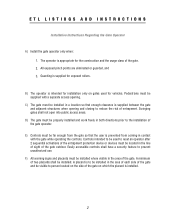
... user is installed. 2 Easily accessible controls shall have a security feature to the installation of the gate outdoor. Controls intended to reset an operator after 2 sequential activations of entrapment. Swinging gates shall not open into public access areas. C) The gate must be installed where visible in ...the gate and be visible to person located on the side of the gate on gates used to be supplied with the gate while operating the controls. F) All warning signs and placards must be far enough from coming in both directions prior to prevent unauthorized use. A...
... user is installed. 2 Easily accessible controls shall have a security feature to the installation of the gate outdoor. Controls intended to reset an operator after 2 sequential activations of entrapment. Swinging gates shall not open into public access areas. C) The gate must be installed where visible in ...the gate and be visible to person located on the side of the gate on gates used to be supplied with the gate while operating the controls. F) All warning signs and placards must be far enough from coming in both directions prior to prevent unauthorized use. A...
MIRACLE ONE Manual
Page 4
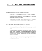
...sensor shall function under the intended end-use conditions. 3. Care shall be located and its arc of travel, one that the communication between the sensor and the gate operator is not subjected to reduce the risk of nuisance tripping, such as when a vehicle trips the sensor while ...risk of a swing gate. One or more non-contact sensors shall be located on the placement of a swing gate is still moving gate or barrier. H) For a gate operator utilizing a contact sensor such as a photo beam: 1. ETL LISTINGS AND INSTRUCTIONS G) For a gate operator utilizing a non-contact sensor...
...sensor shall function under the intended end-use conditions. 3. Care shall be located and its arc of travel, one that the communication between the sensor and the gate operator is not subjected to reduce the risk of nuisance tripping, such as when a vehicle trips the sensor while ...risk of a swing gate. One or more non-contact sensors shall be located on the placement of a swing gate is still moving gate or barrier. H) For a gate operator utilizing a contact sensor such as a photo beam: 1. ETL LISTINGS AND INSTRUCTIONS G) For a gate operator utilizing a non-contact sensor...
MIRACLE ONE Manual
Page 5
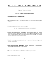
...hardware. 7. Read the manual. SAVE THESE INSTRUCTIONS. 4 ETL LISTINGS AND INSTRUCTIONS Important Safety Instructions Warning - Test the gate operator monthly. KEEP GATES PROPERLY MAINTAINED. NO ONE SHOULD CROSS THE PATH OF A MOVING GATE! 4. The gate MUST reverse on contact with gate controls. The entrance is ...off. 6. Never let children operate or play with a rigid object or stop when an object activates the non-...
...hardware. 7. Read the manual. SAVE THESE INSTRUCTIONS. 4 ETL LISTINGS AND INSTRUCTIONS Important Safety Instructions Warning - Test the gate operator monthly. KEEP GATES PROPERLY MAINTAINED. NO ONE SHOULD CROSS THE PATH OF A MOVING GATE! 4. The gate MUST reverse on contact with gate controls. The entrance is ...off. 6. Never let children operate or play with a rigid object or stop when an object activates the non-...

MIRACLE ONE Manual
Page 6
... or fence system that is prevented via supervision by persons or vehicles and completes the perimeter of one-to service the general public. A vehicular gate operator (or system) that controls a gate which unauthorized access is intended for use for use in ..., sliding, raising lowering, rolling, or like . Commercial/General access vehicular gate operator - Commercial/General access vehicular gate operator - Class I - Vehicular horizontal slide-gate operator (or system) - A vehicular gate operator (or system) intended for use in an industrial location or building such as ...
... or fence system that is prevented via supervision by persons or vehicles and completes the perimeter of one-to service the general public. A vehicular gate operator (or system) that controls a gate which unauthorized access is intended for use for use in ..., sliding, raising lowering, rolling, or like . Commercial/General access vehicular gate operator - Commercial/General access vehicular gate operator - Class I - Vehicular horizontal slide-gate operator (or system) - A vehicular gate operator (or system) intended for use in an industrial location or building such as ...
MIRACLE ONE Manual
Page 7
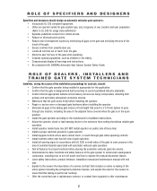
...proceedings for each job, should design an automatic vehicular gate system to: • Incorporate UL 325 compliant equipment. • Utilize an operator suited for usage class definitions) • Separate pedestrian access from vehicle access. • Reduce or eliminate pinch points. • ... as children or the elderly. • Conspicuously display all gaps in the area of potential hazards associated with automatic vehicular gate operation. • Test all features for proper functions before placing the automatic vehicular gate into service. • Demonstrate the basic functions...
...proceedings for each job, should design an automatic vehicular gate system to: • Incorporate UL 325 compliant equipment. • Utilize an operator suited for usage class definitions) • Separate pedestrian access from vehicle access. • Reduce or eliminate pinch points. • ... as children or the elderly. • Conspicuously display all gaps in the area of potential hazards associated with automatic vehicular gate operation. • Test all features for proper functions before placing the automatic vehicular gate into service. • Demonstrate the basic functions...

MIRACLE ONE Manual
Page 8
...the gate) • Retain and utilize the installation and maintenance manual and safety instructions. • Routinely check all gate operator functions and gate movement. • Discontinue use if safety systems operate improperly, the gate is damaged, or the gate is difficult to move. • Never overtighten the... at all obstructions clear of the vicinity of the path of the gate system. • Actively discourage pedestrian use of the vehicular gate operating system. • Prevent anyone from playing near any part of the gate system. • Never allow anyone to climb under, over ...
...the gate) • Retain and utilize the installation and maintenance manual and safety instructions. • Routinely check all gate operator functions and gate movement. • Discontinue use if safety systems operate improperly, the gate is damaged, or the gate is difficult to move. • Never overtighten the... at all obstructions clear of the vicinity of the path of the gate system. • Actively discourage pedestrian use of the vehicular gate operating system. • Prevent anyone from playing near any part of the gate system. • Never allow anyone to climb under, over ...

MIRACLE ONE Manual
Page 9
... and objects until it is not responsible for Vehicular Gate use ONLY! NO ONE SHOULD CROSS THE PATH OF THE MOVING GATE. 4. KEEP GATES PROPERLY MAINTAINED. To reduce the risk of injury to persons, The Miracle-1 is to comply with gate controls. DO NOT install upside down. DO ...gate. DO NOT install next to sprinklers or any area that may expose bottom of operator to read and follow all these important instructions before installation of severe injury or death: 1. Never let children operate or play with local building and electrical codes. Have a qualified service person periodically ...
... and objects until it is not responsible for Vehicular Gate use ONLY! NO ONE SHOULD CROSS THE PATH OF THE MOVING GATE. 4. KEEP GATES PROPERLY MAINTAINED. To reduce the risk of injury to persons, The Miracle-1 is to comply with gate controls. DO NOT install upside down. DO ...gate. DO NOT install next to sprinklers or any area that may expose bottom of operator to read and follow all these important instructions before installation of severe injury or death: 1. Never let children operate or play with local building and electrical codes. Have a qualified service person periodically ...
MIRACLE ONE Manual
Page 12
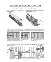
...gate crossbar, weld bar across all pickets. Step 4: Position and level the operator brackets and reinforcement plates. (See next page). Important: Tack weld the front steel bracket at the top of the gate frame. The Miracle 1 can withstand heavy forces. Tack weld brackets and plates in an area that... mounting. Additional reinforcement steel plates may be mounted on top of the crossbar, so the operator will bend. Do not weld the crossbar on the closed gate, where desired. Step 3: Position the Miracle 1 horizontally level on a few pickets, or they will not hit the crossbar when in...
...gate crossbar, weld bar across all pickets. Step 4: Position and level the operator brackets and reinforcement plates. (See next page). Important: Tack weld the front steel bracket at the top of the gate frame. The Miracle 1 can withstand heavy forces. Tack weld brackets and plates in an area that... mounting. Additional reinforcement steel plates may be mounted on top of the crossbar, so the operator will bend. Do not weld the crossbar on the closed gate, where desired. Step 3: Position the Miracle 1 horizontally level on a few pickets, or they will not hit the crossbar when in...
MIRACLE ONE Manual
Page 13
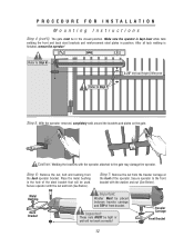
... INSTALLATION Mounting Instructions Step 4 (con't): The gate must be tight or unit will be placed between traveler carriage and TOP of the operator. Step 6: Remove the nut, bolt and bushing from the traveler carriage at the front of front bracket. Important: These nuts MUST ...). Caution: Welding the brackets with the nut and bolt (See Below). Step 7: Remove the nut from the back operator bracket. Make sure the operator is finished, remove the operator! Metal Bushing Back Bracket Important: Washer Must be used. After all tack welding is kept level while tack welding the...
... INSTALLATION Mounting Instructions Step 4 (con't): The gate must be tight or unit will be placed between traveler carriage and TOP of the operator. Step 6: Remove the nut, bolt and bushing from the traveler carriage at the front of front bracket. Important: These nuts MUST ...). Caution: Welding the brackets with the nut and bolt (See Below). Step 7: Remove the nut from the back operator bracket. Make sure the operator is finished, remove the operator! Metal Bushing Back Bracket Important: Washer Must be used. After all tack welding is kept level while tack welding the...
MIRACLE ONE Manual
Page 14
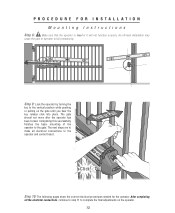
... been locked. Step 10: The following pages show the correct electrical procedures needed for the operator. The next steps are to make all the electrical connections, continue to step 11 to complete the final adjustments on the gate until you ... click into place. Completing this successfully finishes the basic mounting of the operator to fail prematurely. An off-level installation may cause the gate or operator to the gate. PROCEDURE FOR INSTALLATION Mounting Instructions Step 8: Make sure that the operator is level or it will not function properly. Push or Pull Click...
... been locked. Step 10: The following pages show the correct electrical procedures needed for the operator. The next steps are to make all the electrical connections, continue to step 11 to complete the final adjustments on the gate until you ... click into place. Completing this successfully finishes the basic mounting of the operator to fail prematurely. An off-level installation may cause the gate or operator to the gate. PROCEDURE FOR INSTALLATION Mounting Instructions Step 8: Make sure that the operator is level or it will not function properly. Push or Pull Click...
MIRACLE ONE Manual
Page 15
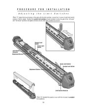
... Switch Armature Adjustment Screws Outside Limit Switch Inside Limit Switch Adjustment Screws Inside Limit Switch Outside Limit Switch Limit Switch Armature Step 12: Reinstall the operator cover with the limit switches. Loosen the 2 screws of each armature to stop the gate in the "full open" and "full closed" positions. PROCEDURE FOR...
... Switch Armature Adjustment Screws Outside Limit Switch Inside Limit Switch Adjustment Screws Inside Limit Switch Outside Limit Switch Limit Switch Armature Step 12: Reinstall the operator cover with the limit switches. Loosen the 2 screws of each armature to stop the gate in the "full open" and "full closed" positions. PROCEDURE FOR...

MIRACLE ONE Manual
Page 17
... GREEN BLACK WHITE RED BROWN BLUE GREEN BURGLAR ALARM INPUT UL SENSOR CENTER LOOP SAFETY LOOP STRIKE INPUT GROUND RADIO +24 VOLT +24 VAC INPUT MIRACLE SURGE PROTECTION REV A ® LAKE FOREST, CALIFORNIA www.eliteaccess.com SINGLE OR MASTER ONLY MOTOR BRAKE LIMITS 12 3 456 SECOND ONLY MOTOR BRAKE LIMITS ...) to secure the wire to eventually break. Shield must be used, Install a dedicated water tight conduit for the blue and green lines. MIRACLE SURGE PROTECTION ® WIRING 1 OPERATOR TO BOARD LAKE FOREST, CALIFORNIA www.eliteaccess.com Caution: Do Not over-bend the cord from the...
... GREEN BLACK WHITE RED BROWN BLUE GREEN BURGLAR ALARM INPUT UL SENSOR CENTER LOOP SAFETY LOOP STRIKE INPUT GROUND RADIO +24 VOLT +24 VAC INPUT MIRACLE SURGE PROTECTION REV A ® LAKE FOREST, CALIFORNIA www.eliteaccess.com SINGLE OR MASTER ONLY MOTOR BRAKE LIMITS 12 3 456 SECOND ONLY MOTOR BRAKE LIMITS ...) to secure the wire to eventually break. Shield must be used, Install a dedicated water tight conduit for the blue and green lines. MIRACLE SURGE PROTECTION ® WIRING 1 OPERATOR TO BOARD LAKE FOREST, CALIFORNIA www.eliteaccess.com Caution: Do Not over-bend the cord from the...

MIRACLE ONE Manual
Page 18
WIRING 2 OPERATORS MASTER / SECOND MIRACLE SURGE PROTECTION MIRACLE SURGE PROTECTION ® LAKE FOREST, CALIFORNIA www.eliteaccess.com 6 Wires, 16 AWG from operator in same conduit! Water Tight J-Box Kit Elite # K55-09853 Black White Red Brown Blue Green Black ...: Make sure BARE WIRE makes good contact inside removable terminal connectors. Operator 2 (Second) REV A Operator 1 (Master) Caution: Do Not use Shielded Wire for the Second Operator. Important: Install the Conduit (supplied) to secure the Master Operator to 200 Ft. Shield must be grounded. 17 Water Tight Conduit...
WIRING 2 OPERATORS MASTER / SECOND MIRACLE SURGE PROTECTION MIRACLE SURGE PROTECTION ® LAKE FOREST, CALIFORNIA www.eliteaccess.com 6 Wires, 16 AWG from operator in same conduit! Water Tight J-Box Kit Elite # K55-09853 Black White Red Brown Blue Green Black ...: Make sure BARE WIRE makes good contact inside removable terminal connectors. Operator 2 (Second) REV A Operator 1 (Master) Caution: Do Not use Shielded Wire for the Second Operator. Important: Install the Conduit (supplied) to secure the Master Operator to 200 Ft. Shield must be grounded. 17 Water Tight Conduit...
MIRACLE ONE Manual
Page 19
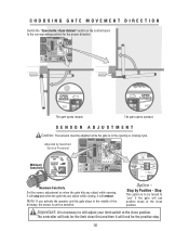
Option - Note: If you activate the operator and the gate stops in the opening , it will use positive stops at the close position. Adjusted by Positive - Stop by Qualified Service Personnel Minimum ...
Option - Note: If you activate the operator and the gate stops in the opening , it will use positive stops at the close position. Adjusted by Positive - Stop by Qualified Service Personnel Minimum ...

MIRACLE ONE Manual
Page 20
...ground rod must be a single, whole piece of a direct lightning strike, proper grounding can protect the gate operator in most cases. Connect ground wire to green wire from the gate operator. Without this path, the intense energy generated by lightning could be located within 3 feet from surge suppressor board...of wire. Use the proper type earth ground rod for your area. 8 Ft The ground wire must be directed towards the Elite gate operator. Timer On Set Timer 1 to 60 Seconds ADJUSTABLE TIMER Timer Off If secondary safety sensor devices are not used when timer is not ...
...ground rod must be a single, whole piece of a direct lightning strike, proper grounding can protect the gate operator in most cases. Connect ground wire to green wire from the gate operator. Without this path, the intense energy generated by lightning could be located within 3 feet from surge suppressor board...of wire. Use the proper type earth ground rod for your area. 8 Ft The ground wire must be directed towards the Elite gate operator. Timer On Set Timer 1 to 60 Seconds ADJUSTABLE TIMER Timer Off If secondary safety sensor devices are not used when timer is not ...
MIRACLE ONE Manual
Page 23
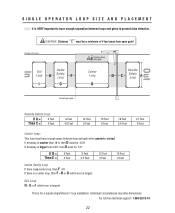
... If there is no center loop, then F 4 ft If there is a center loop, then F = B or G which ever is largest. Individual circumstances may alter dimensions. SINGLE OPERATOR LOOP SIZE AND PLACEMENT It is VERY important to have enough space between loops and gates to scale Exit Loop Inside H Safety Loop F I which ever...: This loop must be a minimum of 4 feet away from open gate Center Loop B Outside D C Safety Loop A End of open gate! This is for a typical single Miracle 1 loop installation.
... If there is no center loop, then F 4 ft If there is a center loop, then F = B or G which ever is largest. Individual circumstances may alter dimensions. SINGLE OPERATOR LOOP SIZE AND PLACEMENT It is VERY important to have enough space between loops and gates to scale Exit Loop Inside H Safety Loop F I which ever...: This loop must be a minimum of 4 feet away from open gate Center Loop B Outside D C Safety Loop A End of open gate! This is for a typical single Miracle 1 loop installation.
MIRACLE ONE Manual
Page 26
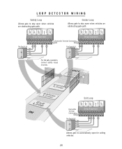
... open when vehicles are obstructing gate path. Center Loop Allows gate to stay open for exiting vehicles. 25 Gnd +24V 23 25 For fail safe operation, connect safety loops in series. OUT LSoaofepty L Coeonpter LSoaofepty LoEoxpit IN Exit Loop CENTER LOOP SAFETY LOOP STRIKE INPUT GROUND RADIO +24 VOLT +24 VAC...
... open when vehicles are obstructing gate path. Center Loop Allows gate to stay open for exiting vehicles. 25 Gnd +24V 23 25 For fail safe operation, connect safety loops in series. OUT LSoaofepty L Coeonpter LSoaofepty LoEoxpit IN Exit Loop CENTER LOOP SAFETY LOOP STRIKE INPUT GROUND RADIO +24 VOLT +24 VAC...

MIRACLE ONE Manual
Page 27
PHOTOCELL INSTALLATION To reduce the risk of injury, You must be in class I or class II gate operator, like the following: OMRON Retro-Reflective Photocell, Model: E3K-R10K4-NR BURGLAR ALARM INPUT UL SENSOR CENTER LOOP SAFETY LOOP STRIKE INPUT GROUND RADIO +24 ...
PHOTOCELL INSTALLATION To reduce the risk of injury, You must be in class I or class II gate operator, like the following: OMRON Retro-Reflective Photocell, Model: E3K-R10K4-NR BURGLAR ALARM INPUT UL SENSOR CENTER LOOP SAFETY LOOP STRIKE INPUT GROUND RADIO +24 ...
MIRACLE ONE Manual
Page 30
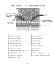
SURGE SUPPRESSOR BOARD DESCRIPTION MIRACLE SURGE PROTECTION Master/Second J1 Surge Suppressor REV A Plug Shown ® LAKE FOREST, CALIFORNIA www.eliteaccess.com J3 Plug ...Operator (Power) 2 White Wire from Operator (Power) 3 Red Wire from Operator (Brake) 4 Brown Wire from Operator (Brake) 5 Blue Wire from Operator (Limits) Single or Master Operator Only 6 Green Wire from Operator (Limits) 7 Black Wire from Operator (Power) 8 White Wire from Operator (Power) 9 Red Wire from Operator (Brake) 10 Brown Wire from Operator (Brake) 11 Blue Wire from Operator (Limits) Second Operator...
SURGE SUPPRESSOR BOARD DESCRIPTION MIRACLE SURGE PROTECTION Master/Second J1 Surge Suppressor REV A Plug Shown ® LAKE FOREST, CALIFORNIA www.eliteaccess.com J3 Plug ...Operator (Power) 2 White Wire from Operator (Power) 3 Red Wire from Operator (Brake) 4 Brown Wire from Operator (Brake) 5 Blue Wire from Operator (Limits) Single or Master Operator Only 6 Green Wire from Operator (Limits) 7 Black Wire from Operator (Power) 8 White Wire from Operator (Power) 9 Red Wire from Operator (Brake) 10 Brown Wire from Operator (Brake) 11 Blue Wire from Operator (Limits) Second Operator...


