
SW420 GL BOARD Manual
Page 4
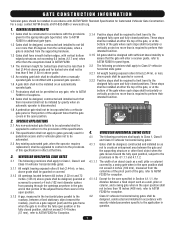
... - SAFETY ACCESSORY SELECTION All UL325 compliant LiftMaster gate operators will accept external entrapment protection devices to protect people from motorized gate systems. UL325 requires that is installed on both the open and close directions of entrapment protection systems recognized...for each gate application. CLASS IV - RESIDENTIAL VEHICULAR GATE OPERATOR A vehicular gate operator (or system) intended for use in the gate area. Gate may move at least one of entrapment protection. Constant pressure control. 4 UL325 MODEL CLASSIFICATIONS The SW420 is intended...
... - SAFETY ACCESSORY SELECTION All UL325 compliant LiftMaster gate operators will accept external entrapment protection devices to protect people from motorized gate systems. UL325 requires that is installed on both the open and close directions of entrapment protection systems recognized...for each gate application. CLASS IV - RESIDENTIAL VEHICULAR GATE OPERATOR A vehicular gate operator (or system) intended for use in the gate area. Gate may move at least one of entrapment protection. Constant pressure control. 4 UL325 MODEL CLASSIFICATIONS The SW420 is intended...

SW420 GL BOARD Manual
Page 5
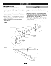
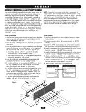
... Telephone Entry System STREET Interrupt (Safety) Loop Photo eye for close cycle DUAL SWING GATE SYSTEM Photo eye for open cycle Run twisted wire* from loop to operator Seal Loops* Shadow Loop Interrupt (Safety) Loop 4' (1.2 m) Typical 1-1/2" (37 mm) Loop Wire* Layer 1/4" (6 mm)... or larger depending on loop wire size COMPLEX OR PARKING LOT STREET Interrupt (Safety) Loop Gate 1 Photo eye for open cycle Photo eye for close cycle Photo eye for open cycle Gate 2 Shadow Loop Interrupt (Safety) Loop Run twisted wire* from loop to operator Seal Loops* 1-1/2" (37 mm) Loop...
... Telephone Entry System STREET Interrupt (Safety) Loop Photo eye for close cycle DUAL SWING GATE SYSTEM Photo eye for open cycle Run twisted wire* from loop to operator Seal Loops* Shadow Loop Interrupt (Safety) Loop 4' (1.2 m) Typical 1-1/2" (37 mm) Loop Wire* Layer 1/4" (6 mm)... or larger depending on loop wire size COMPLEX OR PARKING LOT STREET Interrupt (Safety) Loop Gate 1 Photo eye for open cycle Photo eye for close cycle Photo eye for open cycle Gate 2 Shadow Loop Interrupt (Safety) Loop Run twisted wire* from loop to operator Seal Loops* 1-1/2" (37 mm) Loop...

SW420 GL BOARD Manual
Page 6
...security feature to start. 10. A wireless contact sensor shall function under , around or through the openings anywhere in the gate, and in the line-of-sight of a swing gate. One or more contact sensors shall be located where the transmission of the signals are guarded or .... Care shall be installed in a location so that the gate covers in both inside and outside of the vehicular gate. 6. c. A wireless contact sensor such as the one on the bottom edge. Swinging gates shall not open position. Reference owner's manual regarding placement of non-contact sensor...
...security feature to start. 10. A wireless contact sensor shall function under , around or through the openings anywhere in the gate, and in the line-of-sight of a swing gate. One or more contact sensors shall be located where the transmission of the signals are guarded or .... Care shall be installed in a location so that the gate covers in both inside and outside of the vehicular gate. 6. c. A wireless contact sensor such as the one on the bottom edge. Swinging gates shall not open position. Reference owner's manual regarding placement of non-contact sensor...
SW420 GL BOARD Manual
Page 7
... have smooth bottom edges, with vertical bottom edged protrusions not exceeding 0.5 inches (12.7 mm) when other fixed object when the gate moves toward the fully open position, subject to the provisions in the 4.1.1.1 and 4.1.1.2. 4.1.1.1 The width of an object (such as a wall, pillar or column) covered by gravity when an automatic ...
... have smooth bottom edges, with vertical bottom edged protrusions not exceeding 0.5 inches (12.7 mm) when other fixed object when the gate moves toward the fully open position, subject to the provisions in the 4.1.1.1 and 4.1.1.2. 4.1.1.1 The width of an object (such as a wall, pillar or column) covered by gravity when an automatic ...

SW420 GL BOARD Manual
Page 8
... AVERTISSEMENT WARNING SIGN PLACEMENT WARNING To prevent SERIOUS INJURY or DEATH from a moving gate: CAUTION • Entrapment protection devices MUST be installed to protect between moving gate and RIGID objects, such as posts. • A swinging gate shall NOT open and close gate cycles. • Locate entrapment protection devices to protect anyone who may move at...
... AVERTISSEMENT WARNING SIGN PLACEMENT WARNING To prevent SERIOUS INJURY or DEATH from a moving gate: CAUTION • Entrapment protection devices MUST be installed to protect between moving gate and RIGID objects, such as posts. • A swinging gate shall NOT open and close gate cycles. • Locate entrapment protection devices to protect anyone who may move at...
SW420 GL BOARD Manual
Page 12
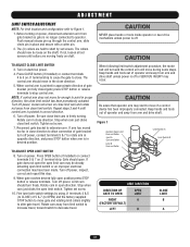
...the control arm should swivel freely about the hub. Mark the point on Operator Arm Stop (Left Open) Arm Stop Kit K75-18624 ADVERTENCIA PRECAUCIÓN Gate 36-1/2" Hinge Pin (Approximately) Fence Gate Bracket Extension Arm 16" 33-1/2" 28" Control Arm Arm Stop 26" Operator Shaft 12 AVERT Extension ... must be prevented from below the hub and through the control arm. Push up the manual release pin from opening and damage to the closed gate. Use 3/8" washers to the extension arm. Left hand or right hand installations call for mounting the arm stop on a structural member of ...
...the control arm should swivel freely about the hub. Mark the point on Operator Arm Stop (Left Open) Arm Stop Kit K75-18624 ADVERTENCIA PRECAUCIÓN Gate 36-1/2" Hinge Pin (Approximately) Fence Gate Bracket Extension Arm 16" 33-1/2" 28" Control Arm Arm Stop 26" Operator Shaft 12 AVERT Extension ... must be prevented from below the hub and through the control arm. Push up the manual release pin from opening and damage to the closed gate. Use 3/8" washers to the extension arm. Left hand or right hand installations call for mounting the arm stop on a structural member of ...

SW420 GL BOARD Manual
Page 13
Figure 1 Clevis Pin Hairpin Cotter Control Arm Drive Hub Release Pin 13 Disconnect the control arm from the gate, so the gate can be manually opened and closed . NOTE: If desired, a padlock can be used in place of the clevis pin to drop down through the hub. The arm should now be free and the gate can be opened or closed normally. INSTALLATION MECHANICAL DISCONNECT The operator can be disconnected from the drive hub by removing the hairpin cotter and then the clevis pin and allowing the manual release pin to hold the manual release pin in place.
Figure 1 Clevis Pin Hairpin Cotter Control Arm Drive Hub Release Pin 13 Disconnect the control arm from the gate, so the gate can be manually opened and closed . NOTE: If desired, a padlock can be used in place of the clevis pin to drop down through the hub. The arm should now be free and the gate can be opened or closed normally. INSTALLATION MECHANICAL DISCONNECT The operator can be disconnected from the drive hub by removing the hairpin cotter and then the clevis pin and allowing the manual release pin to hold the manual release pin in place.

SW420 GL BOARD Manual
Page 16
... now erased. rolling code, billion code, or dip switch remotes. CAUTION AVERTISSEMENT WARNING CONSTANT OPERATION on residential garage door openers because it overrides the safety reversal devices. Pry open the front panel of moving gate or garage door: operate in the Programming Section below to door travel. With the jumper in "C" (Constant) position...
... now erased. rolling code, billion code, or dip switch remotes. CAUTION AVERTISSEMENT WARNING CONSTANT OPERATION on residential garage door openers because it overrides the safety reversal devices. Pry open the front panel of moving gate or garage door: operate in the Programming Section below to door travel. With the jumper in "C" (Constant) position...
SW420 GL BOARD Manual
Page 17
...Limit B Cam and Collar Limit Switch A AAVVEERRT Limit Switch B AVERT ADVERTENCIA PRECAUCIÓN ATTEN AVER LIMIT DIRECTION ADIRDECVTIOEN ORF TENCOPIEAN GATE TO OPEN LIMIT (FPACRTORREIYGCDHETAFAUULTC) IÓNA LEFT B CLOSE LIMIT B A ADVERTENCIA 17 PRECAUCIÓN ADJUSTMENT WARNING LIMIT SWITCH ADJUSTMENT NOTE: ...far enough to move in opposite direction, and press STOP button when arm is freely turning. TO ADJUST OPEN LIMIT SWITCH 8. When gate reaches desired fully open limit switch. Fine tune both switch settings by set screw on close direction. 5. Press CLOSE button (...
...Limit B Cam and Collar Limit Switch A AAVVEERRT Limit Switch B AVERT ADVERTENCIA PRECAUCIÓN ATTEN AVER LIMIT DIRECTION ADIRDECVTIOEN ORF TENCOPIEAN GATE TO OPEN LIMIT (FPACRTORREIYGCDHETAFAUULTC) IÓNA LEFT B CLOSE LIMIT B A ADVERTENCIA 17 PRECAUCIÓN ADJUSTMENT WARNING LIMIT SWITCH ADJUSTMENT NOTE: ...far enough to move in opposite direction, and press STOP button when arm is freely turning. TO ADJUST OPEN LIMIT SWITCH 8. When gate reaches desired fully open limit switch. Fine tune both switch settings by set screw on close direction. 5. Press CLOSE button (...
SW420 GL BOARD Manual
Page 19
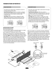
...accesses the SAM system during high traffic times, connect the device's N/O relay output to initiate the SAM systems closure. Install conduit between the BG770 SW420. 3. Attach a wire from the SAMS relay terminal (J5) on the control board to pass through the SAM system. 4. Attach a wire from... in how you are planning to latch the slide or swing gate open during the slide or swing gates closing . 5. Once the slide or swing gate reaches the open position the barrier will automatically close the barrier will open and allow the vehicle to terminal 1 on the BG770 terminal strip. 5....
...accesses the SAM system during high traffic times, connect the device's N/O relay output to initiate the SAM systems closure. Install conduit between the BG770 SW420. 3. Attach a wire from the SAMS relay terminal (J5) on the control board to pass through the SAM system. 4. Attach a wire from... in how you are planning to latch the slide or swing gate open during the slide or swing gates closing . 5. Once the slide or swing gate reaches the open position the barrier will automatically close the barrier will open and allow the vehicle to terminal 1 on the BG770 terminal strip. 5....

SW420 GL BOARD Manual
Page 20
...FREQ 24 Vac Control Board J1 Terminals 1 & 5 - This input protects cars by preventing the gate from moving off of the open the gate by activating the remote control when the gate is active. Latching this input include: Telephone Entry Systems, Radio Receiver (Commercial Applications), Exit Loop Detector... devices for use with a radio receiver in safety. Refer to open or close the gate by the gate stopped and entrapment alarm on radio terminal block. This input functions to reverse a closing gate to close limit when the shadow loop input is closed or between...
...FREQ 24 Vac Control Board J1 Terminals 1 & 5 - This input protects cars by preventing the gate from moving off of the open the gate by activating the remote control when the gate is active. Latching this input include: Telephone Entry Systems, Radio Receiver (Commercial Applications), Exit Loop Detector... devices for use with a radio receiver in safety. Refer to open or close the gate by the gate stopped and entrapment alarm on radio terminal block. This input functions to reverse a closing gate to close limit when the shadow loop input is closed or between...

SW420 GL BOARD Manual
Page 21
...Control Input These terminals are intended for use with the close , if enabled, will pause an opening gate to be disabled until a stop the gate or to open limit. NOTE: If upon reversal a second separate obstruction is closing will not run until another command...If upon reversal a second separate obstruction is installed within line of site of this input will have no effect. A momentary activation of the OPEN gate. ADJUSTMENT ACCESSORY WIRING Field Wiring Terminals 9 & 5 - Obstruction Close (Edge/Photo Eye Input) Edge Input: See Programming Section This input ...
...Control Input These terminals are intended for use with the close , if enabled, will pause an opening gate to be disabled until a stop the gate or to open limit. NOTE: If upon reversal a second separate obstruction is closing will not run until another command...If upon reversal a second separate obstruction is installed within line of site of this input will have no effect. A momentary activation of the OPEN gate. ADJUSTMENT ACCESSORY WIRING Field Wiring Terminals 9 & 5 - Obstruction Close (Edge/Photo Eye Input) Edge Input: See Programming Section This input ...

SW420 GL BOARD Manual
Page 23
... for approximately 1/2 second and repeats every second until the number is moving in an 8 second period. The number is on for the open and close input terminals. LED Code Flashed Diagnostic Meaning Cleared By OFF 1 2 3 4 5 6 On No Flash Normal operation Single ...gate travel but can be performed in the opposite direction. Two red LEDs (OLS, CLS) are three diagnostic LEDs. On most operators this happens try learning while running in stand alone mode. 1. To learn button. The LEDs are illuminated when the limit switch contacts are closed. If either the hard open...
... for approximately 1/2 second and repeats every second until the number is moving in an 8 second period. The number is on for the open and close input terminals. LED Code Flashed Diagnostic Meaning Cleared By OFF 1 2 3 4 5 6 On No Flash Normal operation Single ...gate travel but can be performed in the opposite direction. Two red LEDs (OLS, CLS) are three diagnostic LEDs. On most operators this happens try learning while running in stand alone mode. 1. To learn button. The LEDs are illuminated when the limit switch contacts are closed. If either the hard open...
SW420 GL BOARD Manual
Page 25
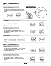
...Close feature works in conjunction with the potentiometer located on the board. SL = Slide • SW = Swing RIGHT/LEFT OPERATION This switch selects the gate opening direction, to the left or to movement and throughout movement. 25 TTC PH SAVE PH SW RT S1 ON ON 1 2 34 SW RT S1 ...in motion" alarm feature. The alarm will be changed. Right/Left operation is released before the motor starts. WARNING ENABLE This switch enables the gate "in OFF position. When switch is ON, no settings can be a half second delay after the maglock relay is determined from the inside of...
...Close feature works in conjunction with the potentiometer located on the board. SL = Slide • SW = Swing RIGHT/LEFT OPERATION This switch selects the gate opening direction, to the left or to movement and throughout movement. 25 TTC PH SAVE PH SW RT S1 ON ON 1 2 34 SW RT S1 ...in motion" alarm feature. The alarm will be changed. Right/Left operation is released before the motor starts. WARNING ENABLE This switch enables the gate "in OFF position. When switch is ON, no settings can be a half second delay after the maglock relay is determined from the inside of...
SW420 GL BOARD Manual
Page 26
... edge or photoelectric sensor for the gate opening cycle. Before initiating any command the master unit queries for the presence of a "second unit" for a time period of no communications. NOTE: Timer-to the master for safety edges, the input functions to reverse the gate to either the master or second.... Master/Second wiring. Close Edge: When the controller is not cleared at the limit and the Timer-to pause the gate during the opening cycle. NOTE: Do not run Master/Second communication wiring in a stand alone mode. After Master/Second wiring has been completed and the S4...
... edge or photoelectric sensor for the gate opening cycle. Before initiating any command the master unit queries for the presence of a "second unit" for a time period of no communications. NOTE: Timer-to the master for safety edges, the input functions to reverse the gate to either the master or second.... Master/Second wiring. Close Edge: When the controller is not cleared at the limit and the Timer-to pause the gate during the opening cycle. NOTE: Do not run Master/Second communication wiring in a stand alone mode. After Master/Second wiring has been completed and the S4...
SW420 GL BOARD Manual
Page 28
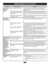
...as well as possible without coming into contact with any power wiring. The operator opens immediately upon power up and does not close gate from the operator and swing the gate open limit. Both LEDs will run in interference across the master/second communication line. ...Check the save switch on . Open photo eye reverses gate closed when activated during opening. Refer to fail. TROUBLESHOOTING ...
...as well as possible without coming into contact with any power wiring. The operator opens immediately upon power up and does not close gate from the operator and swing the gate open limit. Both LEDs will run in interference across the master/second communication line. ...Check the save switch on . Open photo eye reverses gate closed when activated during opening. Refer to fail. TROUBLESHOOTING ...

SW420 GL BOARD Manual
Page 30
... R1 SEE NOTE 4 J4 DUAL GATE 1 2 SEE NOTE 1 PRIMARY R2 24VA C SEC SEE NOTE 5 J1-11 J1-6 OPTIONAL WIRE (OR) HARNESS P/N 90-G0601 FIELD WIRING R1 R2 R3 R4 35 5 8 9 10 11 12 24 VAC RADIO SIGNAL STOP INTERRUPT LOOP ENTRAPMENT OPEN ENTRAPMENT CLOSE TO PRIMARY/SECONDARY UNIT NOTES...GL CONTROL BOARD 24VAC-IN 24VAC-COMMON SOFT OPEN NC "B" LIMIT CONTACTOR B "A" LIMIT CONTACTOR A RPM-IN RPM-SUPPLY RPM GND RADIO COMMAND SHADOW +24 VDC CLOSE STOP SOFT OPEN HARD OPEN INT. LOOP OBS. GL FIELD WIRING & ADJUSTMENTS MODEL TYPES: HORSEPOWER: VOLTAGE/PHASE: SW420 1/3 115V & 230V - 1 PHASE ONLY...
... R1 SEE NOTE 4 J4 DUAL GATE 1 2 SEE NOTE 1 PRIMARY R2 24VA C SEC SEE NOTE 5 J1-11 J1-6 OPTIONAL WIRE (OR) HARNESS P/N 90-G0601 FIELD WIRING R1 R2 R3 R4 35 5 8 9 10 11 12 24 VAC RADIO SIGNAL STOP INTERRUPT LOOP ENTRAPMENT OPEN ENTRAPMENT CLOSE TO PRIMARY/SECONDARY UNIT NOTES...GL CONTROL BOARD 24VAC-IN 24VAC-COMMON SOFT OPEN NC "B" LIMIT CONTACTOR B "A" LIMIT CONTACTOR A RPM-IN RPM-SUPPLY RPM GND RADIO COMMAND SHADOW +24 VDC CLOSE STOP SOFT OPEN HARD OPEN INT. LOOP OBS. GL FIELD WIRING & ADJUSTMENTS MODEL TYPES: HORSEPOWER: VOLTAGE/PHASE: SW420 1/3 115V & 230V - 1 PHASE ONLY...

SW420 GL BOARD Manual
Page 34
... SHADOW LOOP INPUT (N.O.) STOP/RESET CONTROL INPUT (N.C.) OPEN CLOSE STOP INTERRUPT (SAFETY) LOOP INPUT (N.O.) OBSTRUCTION OPEN EDGE/PHOTO EYE INPUT (N.O.) OBSTRUCTION CLOSE EDGE/PHOTO EYE INPUT (N.O.) RESIDENTIAL RADIO (SINGLE BUTTON) INPUT (N.O.) SW420 Operator 34 Also, always install the controls where the user has full view of gate operation. * All inputs are to be installed...
... SHADOW LOOP INPUT (N.O.) STOP/RESET CONTROL INPUT (N.C.) OPEN CLOSE STOP INTERRUPT (SAFETY) LOOP INPUT (N.O.) OBSTRUCTION OPEN EDGE/PHOTO EYE INPUT (N.O.) OBSTRUCTION CLOSE EDGE/PHOTO EYE INPUT (N.O.) RESIDENTIAL RADIO (SINGLE BUTTON) INPUT (N.O.) SW420 Operator 34 Also, always install the controls where the user has full view of gate operation. * All inputs are to be installed...

SW420 S3 BOARD Manual
Page 5
General Information 5 Specifications Power: 115vac. Split cap. Gate Travel: Adjustable to 105 degrees. Gate Speed: Opens in 12 seconds. Motor: Perm. GATE WIDTH MAX. STARTS/HR. 1/3 300 lbs. 12 ft. 10 Table 3 01-G0610F2 Figure 1 Doc 01-G0610 Rev A Speed - 1000 rpm Current - 5.2A @ 115v. 2.6A @ 230v. Or 230vac. 60 hz. 6.5 amps @ 115v. 3.3 amps @ 230v. RECOMMENDED CAPACITIES HP GATE WT. Overload: Automatic resetting thermal.
General Information 5 Specifications Power: 115vac. Split cap. Gate Travel: Adjustable to 105 degrees. Gate Speed: Opens in 12 seconds. Motor: Perm. GATE WIDTH MAX. STARTS/HR. 1/3 300 lbs. 12 ft. 10 Table 3 01-G0610F2 Figure 1 Doc 01-G0610 Rev A Speed - 1000 rpm Current - 5.2A @ 115v. 2.6A @ 230v. Or 230vac. 60 hz. 6.5 amps @ 115v. 3.3 amps @ 230v. RECOMMENDED CAPACITIES HP GATE WT. Overload: Automatic resetting thermal.

SW420 S3 BOARD Manual
Page 7
...of the sensor(s) to the operator. FOR GATE OPERATORS USING CONTACT SENSOR(S) One or more than one sensor should be damaged or interrupted. Precautions must be conspicuous. 7 Install operator inside fence line. Use photo eyes, safety edges or both the open and close directions. Doc 01-G0610 Rev A... In any case, the device must be taken during the wiring of automatic gate operation. DO NOT install operator on public side of entrapment or obstruction, then more...
...of the sensor(s) to the operator. FOR GATE OPERATORS USING CONTACT SENSOR(S) One or more than one sensor should be damaged or interrupted. Precautions must be conspicuous. 7 Install operator inside fence line. Use photo eyes, safety edges or both the open and close directions. Doc 01-G0610 Rev A... In any case, the device must be taken during the wiring of automatic gate operation. DO NOT install operator on public side of entrapment or obstruction, then more...


