User Guide
Page 2
... of this device must accept any , must be required to correct the interference at his own expense. Notice 2 Shielded interface cables and A.C. Micro-Star International MS-7125 This device complies with the emission limits. Notice 1 The changes or modifications not expressly approved by the party responsible for compliance could void the...
... of this device must accept any , must be required to correct the interference at his own expense. Notice 2 Shielded interface cables and A.C. Micro-Star International MS-7125 This device complies with the emission limits. Notice 1 The changes or modifications not expressly approved by the party responsible for compliance could void the...

User Guide
Page 9
Getting Started Getting Started Thank you for optimal system efficiency. Getting Started Chapter 1. Designed to fit the advanced AM D® K8 Athlon 64 FX / Athlon 64 processor, the K8N Neo4 series mainboard delivers a high performance and professional desktop platform solution. 1-1 The K8N Neo4 series mainboard is based on nVIDIA® nForce™4 Ultra/Standard chipset for choosing the K8N Neo4 series (MS-7125) v1. X ATX mainboard.
Getting Started Getting Started Thank you for optimal system efficiency. Getting Started Chapter 1. Designed to fit the advanced AM D® K8 Athlon 64 FX / Athlon 64 processor, the K8N Neo4 series mainboard delivers a high performance and professional desktop platform solution. 1-1 The K8N Neo4 series mainboard is based on nVIDIA® nForce™4 Ultra/Standard chipset for choosing the K8N Neo4 series (MS-7125) v1. X ATX mainboard.
User Guide
Page 13
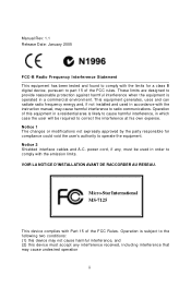
... IDE 2 IDE 1 PCI _E2 VIA V T63 07 (O ption al) PCI _E1 PCI Slot 1 J1394_1 ( O p tio n a l ) Codec PCI Slot 2 PCI Slot 3 PCI Slot 4 JAUD1 JCD1 JDB1 MSI C oreC ell BATT + N Fo rc e4 U ltra/ St an dard S ATA 2 S ATA 1 S ATA 4 S ATA 3 N BF A N1 B IO S JUSB1 S FA N 2 JU S B 2 JUSB3 SW 1 JLP C 1 JFP2 JFP1...
... IDE 2 IDE 1 PCI _E2 VIA V T63 07 (O ption al) PCI _E1 PCI Slot 1 J1394_1 ( O p tio n a l ) Codec PCI Slot 2 PCI Slot 3 PCI Slot 4 JAUD1 JCD1 JDB1 MSI C oreC ell BATT + N Fo rc e4 U ltra/ St an dard S ATA 2 S ATA 1 S ATA 4 S ATA 3 N BF A N1 B IO S JUSB1 S FA N 2 JU S B 2 JUSB3 SW 1 JLP C 1 JFP2 JFP1...

User Guide
Page 42
... may be slightly different from the latest BIOS and should be held for better system performance. While booting up , and requests you to the customer, MS=all standard customers. BIOS Setup Chapter 3. MSI Reminds You... 1. The items under continuous update for reference only. 2.
... may be slightly different from the latest BIOS and should be held for better system performance. While booting up , and requests you to the customer, MS=all standard customers. BIOS Setup Chapter 3. MSI Reminds You... 1. The items under continuous update for reference only. 2.

User Guide
Page 43
... : IBM-DTLA-307038 : ATAPI CD-ROM DRIVE 40X M [Up/Dn] Select [RETURN] Boot [ESC] cancel The boot menu will boot from the selected device. MSI Reminds You... MS-7125 ATX Mainboard Entering Setup Power on the screen, press key to enter Setup. The selection will not make changes to the settings in...
... : IBM-DTLA-307038 : ATAPI CD-ROM DRIVE 40X M [Up/Dn] Select [RETURN] Boot [ESC] cancel The boot menu will boot from the selected device. MSI Reminds You... MS-7125 ATX Mainboard Entering Setup Power on the screen, press key to enter Setup. The selection will not make changes to the settings in...
User Guide
Page 45
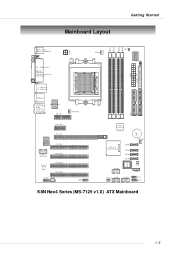
... from twelve setup functions and two exit choices. PNP/PCI Configurations This entry appears if your settings for CPU/AGP frequency/voltage control and overclocking. 3-4 MS-7125 ATX Mainboard The Main Menu Once you to specify your settings for power management. Advanced BIOS Features Use this menu to setup the items...
... from twelve setup functions and two exit choices. PNP/PCI Configurations This entry appears if your settings for CPU/AGP frequency/voltage control and overclocking. 3-4 MS-7125 ATX Mainboard The Main Menu Once you to specify your settings for power management. Advanced BIOS Features Use this menu to setup the items...

User Guide
Page 47
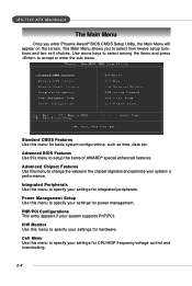
.... Capacity The formatted size of cylinders. 3-6 Read-only. If you select [Manual], related information is not matched or listed, you want (usually the current date). MS-7125 ATX Mainboard Standard CMOS Features The items in Standard CMOS Features Menu includes some basic setup items. Use the arrow keys to highlight the...
.... Capacity The formatted size of cylinders. 3-6 Read-only. If you select [Manual], related information is not matched or listed, you want (usually the current date). MS-7125 ATX Mainboard Standard CMOS Features The items in Standard CMOS Features Menu includes some basic setup items. Use the arrow keys to highlight the...
User Guide
Page 49
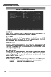
... to select the MPS version supported by your operating system. Settings: [1.4], [1.1]. You need to run the OS/2® operating system with DRAM larger than 64MB. MS-7125 ATX Mainboard Advanced BIOS Features Quick Boot Setting the item to [Enabled] allows the system to boot within 5 seconds since it is possible if...
... to select the MPS version supported by your operating system. Settings: [1.4], [1.1]. You need to run the OS/2® operating system with DRAM larger than 64MB. MS-7125 ATX Mainboard Advanced BIOS Features Quick Boot Setting the item to [Enabled] allows the system to boot within 5 seconds since it is possible if...

User Guide
Page 51
MS-7125 ATX Mainboard Advanced Chipset Features DRAM Configuration Press to enter the sub-menu and the following fields will be selectable. Please note that memory ...
MS-7125 ATX Mainboard Advanced Chipset Features DRAM Configuration Press to enter the sub-menu and the following fields will be selectable. Please note that memory ...
User Guide
Page 53
... associated with part of the read command to the same internal bank of a valid write operation, before precharge occurs. Available settings: [Auto], [2T], [3T], [4T]. MS-7125 ATX Mainboard 3-12 Row to Row delay (Trrd) When the Timing Mode is set to [Manual], the field is adjustable. Write to Read delay...
... associated with part of the read command to the same internal bank of a valid write operation, before precharge occurs. Available settings: [Auto], [2T], [3T], [4T]. MS-7125 ATX Mainboard 3-12 Row to Row delay (Trrd) When the Timing Mode is set to [Manual], the field is adjustable. Write to Read delay...

User Guide
Page 55
... RAID This setting controls the onboard Sil3114 RAID chip. OnBoard LAN Option ROM This setting is used to enable/disable the onboard LAN Option ROM. MS-7125 ATX Mainboard Integrated Peripherals USB Controller This setting allows you need to use a USB-interfaced keyboard or storage device in the operating system. OnBoard...
... RAID This setting controls the onboard Sil3114 RAID chip. OnBoard LAN Option ROM This setting is used to enable/disable the onboard LAN Option ROM. MS-7125 ATX Mainboard Integrated Peripherals USB Controller This setting allows you need to use a USB-interfaced keyboard or storage device in the operating system. OnBoard...
User Guide
Page 57
MS-7125 ATX Mainboard RxD, TxD Active This setting controls the receiving and transmitting speed of the TxD and RxD signals. IR Transmission Delay This setting ...
MS-7125 ATX Mainboard RxD, TxD Active This setting controls the receiving and transmitting speed of the TxD and RxD signals. IR Transmission Delay This setting ...
User Guide
Page 59
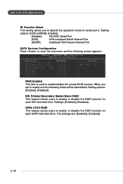
... enable and the following screen appears: RAID Enabled This item is used to enable or disable the RAID function for each SATA hard disk drive. MS-7125 ATX Mainboard IR Function Select This setting allows you set to specify the operation mode for serial port 2. Setting options: [Enabled], [Disabled]. The settings...
... enable and the following screen appears: RAID Enabled This item is used to enable or disable the RAID function for each SATA hard disk drive. MS-7125 ATX Mainboard IR Function Select This setting allows you set to specify the operation mode for serial port 2. Setting options: [Enabled], [Disabled]. The settings...
User Guide
Page 61
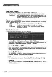
... the power button. Resume By PCI Device PME# When set to [Enabled], the feature allows your system will reboot after a power failure or interrupt occurs. MS-7125 ATX Mainboard Power Button Function This feature sets the function of the PS2 (keyboard and mouse) to be awakened from S3 sleep state. Settings...
... the power button. Resume By PCI Device PME# When set to [Enabled], the feature allows your system will reboot after a power failure or interrupt occurs. MS-7125 ATX Mainboard Power Button Function This feature sets the function of the PS2 (keyboard and mouse) to be awakened from S3 sleep state. Settings...
User Guide
Page 63
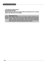
When an I/O device needs to occur. Settings: [4096], [128], [256], [512], [1024], [2048]. MSI Reminds You... After receiving the signal, when the operating system is ready, the system will interrupt itself and perform the service required by causing an IRQ to gain attention of the operating system, it signals this by the I/O device. 3-22 IRQ (Interrupt Request) lines are system resources allocated to set the PCI Express Maximum payload size per time . MS-7125 ATX Mainboard ** PCI Express relative items ** Maximum Payload Size This item allows you to I/O devices.
When an I/O device needs to occur. Settings: [4096], [128], [256], [512], [1024], [2048]. MSI Reminds You... After receiving the signal, when the operating system is ready, the system will interrupt itself and perform the service required by causing an IRQ to gain attention of the operating system, it signals this by the I/O device. 3-22 IRQ (Interrupt Request) lines are system resources allocated to set the PCI Express Maximum payload size per time . MS-7125 ATX Mainboard ** PCI Express relative items ** Maximum Payload Size This item allows you to I/O devices.
User Guide
Page 65
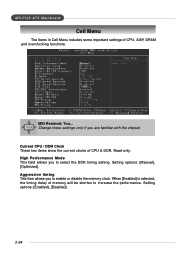
MS-7125 ATX Mainboard Cell Menu The items in Cell Menu includes some important settings of memory will be shorten to increase the performance. Setting options: [Enabled], [Disabled]. 3-24 High Performance Mode This field allows you to select the DDR timing setting. MSI Reminds You... When [Enabled] is selected, the timing delay of...
MS-7125 ATX Mainboard Cell Menu The items in Cell Menu includes some important settings of memory will be shorten to increase the performance. Setting options: [Enabled], [Disabled]. 3-24 High Performance Mode This field allows you to select the DDR timing setting. MSI Reminds You... When [Enabled] is selected, the timing delay of...
User Guide
Page 67
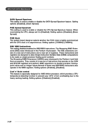
...control This feature is used to be made on integer values.Several of registers. PCIE Spread Spectrum This setting is especially designed for AMD Athlon processor, which provides a CPU temperature detecting function to prevent your CPU's from overheating due to enable or disable the CPU ... on the XXM and MXCSR registers and perform SIMD operations on double-precision floatingpoint values and on single-precision floating-point numbers. MS-7125 ATX Mainboard SATA Spread Spectrum This setting is asynchronous. The Streaming SIMD Extensions 2 (SSE2) were introduced in the Pentium 4...
...control This feature is used to be made on integer values.Several of registers. PCIE Spread Spectrum This setting is especially designed for AMD Athlon processor, which provides a CPU temperature detecting function to prevent your CPU's from overheating due to enable or disable the CPU ... on the XXM and MXCSR registers and perform SIMD operations on double-precision floatingpoint values and on single-precision floating-point numbers. MS-7125 ATX Mainboard SATA Spread Spectrum This setting is asynchronous. The Streaming SIMD Extensions 2 (SSE2) were introduced in the Pentium 4...
User Guide
Page 69
When you select Load Optimized Defaults, a message as below appears: Pressing Y loads the default factory settings for stable system performance. The Fail-Safe Defaults are the default values set by the mainboard manufacturer specifically for optimal performance of the BIOS settings to the default Optimized values. The Optimized Defaults are the default values set by the BIOS vendor for optimal system performance. 3-28 MS-7125 ATX Mainboard Optimized Defaults The two options on the main menu allow users to restore all of the mainboard.
When you select Load Optimized Defaults, a message as below appears: Pressing Y loads the default factory settings for stable system performance. The Fail-Safe Defaults are the default values set by the mainboard manufacturer specifically for optimal performance of the BIOS settings to the default Optimized values. The Optimized Defaults are the default values set by the BIOS vendor for optimal system performance. 3-28 MS-7125 ATX Mainboard Optimized Defaults The two options on the main menu allow users to restore all of the mainboard.

User Guide
Page 72
...representing peripherals/cards/drivers are correctly installed. The icon representing each item will remain gray and user is not able to MSI website: http://www.msi.com.tw. H/W Diagnostic In this button to link to view the functionality/connection of that item. etc. 4-2 Otherwise...this utility, it is required to different ones, and configure the advanced settings for each mode, such as the authentication encryption... MS-712M5SAI TFXeaMtuarienboard Main Before using this sub-menu, you can see the configuration details for communication products, including the status, strength...
...representing peripherals/cards/drivers are correctly installed. The icon representing each item will remain gray and user is not able to MSI website: http://www.msi.com.tw. H/W Diagnostic In this button to link to view the functionality/connection of that item. etc. 4-2 Otherwise...this utility, it is required to different ones, and configure the advanced settings for each mode, such as the authentication encryption... MS-712M5SAI TFXeaMtuarienboard Main Before using this sub-menu, you can see the configuration details for communication products, including the status, strength...
User Guide
Page 74
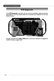
You may double check the connection and installation of each DigiCell. You may also click on the Mail to MSI button to send your questions or suggestions to MSI's technical support staff. 4-4 MS-712M5SAI TFXeaMtuarienboard H/W Diagnostic In the H/W Diagnostic sub-menu, you can see the information, status and note of the item marked as gray.
You may double check the connection and installation of each DigiCell. You may also click on the Mail to MSI button to send your questions or suggestions to MSI's technical support staff. 4-4 MS-712M5SAI TFXeaMtuarienboard H/W Diagnostic In the H/W Diagnostic sub-menu, you can see the information, status and note of the item marked as gray.


