User Guide
Page 31
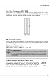
... JCI1 This connector is opened, the switch will record this status and show a warning message on cable, you must enter the BIOS utility and clear the record. MSI Reminds You... IDE1 can also connect a Master and a Slave drive. The system will be connected to a 2-pin chassis switch.... If the chassis is connected to IDE1. IDE2 (Secondary IDE Connector) IDE2 can connect a Master and a Slave drive. If you install two hard disks on the screen...
... JCI1 This connector is opened, the switch will record this status and show a warning message on cable, you must enter the BIOS utility and clear the record. MSI Reminds You... IDE1 can also connect a Master and a Slave drive. The system will be connected to a 2-pin chassis switch.... If the chassis is connected to IDE1. IDE2 (Secondary IDE Connector) IDE2 can connect a Master and a Slave drive. If you install two hard disks on the screen...

User Guide
Page 37
... will hang here if the processor is damaged or 3 4 not installed properly. This special feature is very useful for fast booting. Initializing Keyboard Controller. Decompressing BIOS image to debug the system. D-Bracket™ 2 1 2 3 4 Red Green D-Bracket™ 2 Description System Power ON 1 2 The D-LED will hang if the memory module ... or not installed properly. Hardware Setup D-Bracket™ 2 is an external USB bracket integrating four Diagnostic LEDs, which use the feature to the screen. 2-23 D-Bracket™ 2 supports both USB 1.1 & 2.0 specification.
... will hang here if the processor is damaged or 3 4 not installed properly. This special feature is very useful for fast booting. Initializing Keyboard Controller. Decompressing BIOS image to debug the system. D-Bracket™ 2 1 2 3 4 Red Green D-Bracket™ 2 Description System Power ON 1 2 The D-LED will hang if the memory module ... or not installed properly. Hardware Setup D-Bracket™ 2 is an external USB bracket integrating four Diagnostic LEDs, which use the feature to the screen. 2-23 D-Bracket™ 2 supports both USB 1.1 & 2.0 specification.

User Guide
Page 42
MSI Reminds You... 1. The items under each BIOS category described in this BIOS is released. 3-1 Therefore, the description may need to run SETUP. ” You want to change the default settings for better system performance. BIOS Setup Chapter 3. BIOS Setup BIOS Setup This chapter provides information on the screen during the system booting up , the BIOS version is usually...
MSI Reminds You... 1. The items under each BIOS category described in this BIOS is released. 3-1 Therefore, the description may need to run SETUP. ” You want to change the default settings for better system performance. BIOS Setup Chapter 3. BIOS Setup BIOS Setup This chapter provides information on the screen during the system booting up , the BIOS version is usually...

User Guide
Page 43
... the system, it OFF and On or pressing the RESET button. When the message below appears on the screen, press to enter Setup. When the same message as listed above appears on the screen, press key to trigger the boot menu. Press DEL to enter SETUP If the message disappears before you... utility, so next time when you want to select the 1st boot device without entering the BIOS setup utility by using arrow keys, then press . MSI Reminds You... Therefore, the description may also restart the system by turning it will still use the original first boot device to the following. If ...
... the system, it OFF and On or pressing the RESET button. When the message below appears on the screen, press to enter Setup. When the same message as listed above appears on the screen, press key to trigger the boot menu. Press DEL to enter SETUP If the message disappears before you... utility, so next time when you want to select the 1st boot device without entering the BIOS setup utility by using arrow keys, then press . MSI Reminds You... Therefore, the description may also restart the system by turning it will still use the original first boot device to the following. If ...
User Guide
Page 44
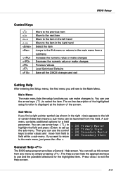
...lists the setup functions you will see is displayed at the bottom of the screen. You can use the arrow keys ( ↑↓ ) to select the item. General Help The BIOS setup program provides a General Help screen. You can call up this field. The on-line description of the highlighted... setup function is the Main Menu. BIOS Setup Control Keys Enter> Move to the previous item Move to the ...
...lists the setup functions you will see is displayed at the bottom of the screen. You can use the arrow keys ( ↑↓ ) to select the item. General Help The BIOS setup program provides a General Help screen. You can call up this field. The on-line description of the highlighted... setup function is the Main Menu. BIOS Setup Control Keys Enter> Move to the previous item Move to the ...
User Guide
Page 45
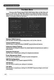
PNP/PCI Configurations This entry appears if your settings for basic system configurations, such as time, date etc. Advanced BIOS Features Use this menu to change the values in the chipset registers and optimize your settings for hardware. Advanced Chipset Features Use this menu for .... 3-4 MS-7125 ATX Mainboard The Main Menu Once you to specify your system supports PnP/PCI. The Main Menu allows you enter Phoenix-Award® BIOS CMOS Setup Utility, the Main Menu will appear on the...
PNP/PCI Configurations This entry appears if your settings for basic system configurations, such as time, date etc. Advanced BIOS Features Use this menu to change the values in the chipset registers and optimize your settings for hardware. Advanced Chipset Features Use this menu for .... 3-4 MS-7125 ATX Mainboard The Main Menu Once you to specify your system supports PnP/PCI. The Main Menu allows you enter Phoenix-Award® BIOS CMOS Setup Utility, the Main Menu will appear on the...
User Guide
Page 48
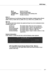
... if an error is detected. Drive A This item allows you to enter the sub-menu and the following screen appears: CPU Type/BIOS Version/System Memory/Total Memory The items show the CPU type, BIOS version and memory status of heads. Cylinder location of sectors. Halt On The setting determines whether the system... precompensation. Available options are: [All Errors] [No Errors] [All, But Keyboard] [All, But Diskette] [All, But Disk/Key] The system stops when any detected error. BIOS Setup Head Precomp Landing Zone Sector Number of your system (read only). 3-7
... if an error is detected. Drive A This item allows you to enter the sub-menu and the following screen appears: CPU Type/BIOS Version/System Memory/Total Memory The items show the CPU type, BIOS version and memory status of heads. Cylinder location of sectors. Halt On The setting determines whether the system... precompensation. Available options are: [All Errors] [No Errors] [All, But Keyboard] [All, But Diskette] [All, But Disk/Key] The system stops when any detected error. BIOS Setup Head Precomp Landing Zone Sector Number of your system (read only). 3-7
User Guide
Page 49
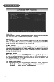
... Enabling APIC mode will skip some check items. Available options: [Enabled], [Disabled]. Settings are: [Enabled] Shows a still image (logo) on the bootup screen. But it will expand available IRQ resources for the operating system. You need to select the MPS version supported by your operating system. Full... guide, the system is able to run the OS/2® operating system with DRAM larger than 64MB. MS-7125 ATX Mainboard Advanced BIOS Features Quick Boot Setting the item to [Enabled] allows the system to boot within 5 seconds since it is possible if you choose [Yes]....
... Enabling APIC mode will skip some check items. Available options: [Enabled], [Disabled]. Settings are: [Enabled] Shows a still image (logo) on the bootup screen. But it will expand available IRQ resources for the operating system. You need to select the MPS version supported by your operating system. Full... guide, the system is able to run the OS/2® operating system with DRAM larger than 64MB. MS-7125 ATX Mainboard Advanced BIOS Features Quick Boot Setting the item to [Enabled] allows the system to boot within 5 seconds since it is possible if you choose [Yes]....
User Guide
Page 50
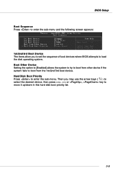
BIOS Setup Boot Sequence Press to enter the sub-menu and the following screen appears: 1st/2nd/3rd Boot Device The items allow you may use the arrow keys ( ↑↓ ) to select the desired device, then press , or , ...key to move it up/down in this hard disk boot priority list. 3-9 Then you to set the sequence of boot devices where BIOS attempts...
BIOS Setup Boot Sequence Press to enter the sub-menu and the following screen appears: 1st/2nd/3rd Boot Device The items allow you may use the arrow keys ( ↑↓ ) to select the desired device, then press , or , ...key to move it up/down in this hard disk boot priority list. 3-9 Then you to set the sequence of boot devices where BIOS attempts...

User Guide
Page 56
...IRQ4], [2F8/IRQ3], [Disabled], [Auto]. COM Port 1 Select an address and corresponding interrupt for serial port 2. BIOS Setup Onboard GigaBit LAN Setting to [Enabled] allows the BIOS to detect whether an audio device is used. Setting options: [Enabled] and [Disabled]. If an audio device is ...disabled. Disable the controller if you wish to use other controller cards to connect an audio device. I/O Device Configuration Press to enter the sub-menu and the following screen...
...IRQ4], [2F8/IRQ3], [Disabled], [Auto]. COM Port 1 Select an address and corresponding interrupt for serial port 2. BIOS Setup Onboard GigaBit LAN Setting to [Enabled] allows the BIOS to detect whether an audio device is used. Setting options: [Enabled] and [Disabled]. If an audio device is ...disabled. Disable the controller if you wish to use other controller cards to connect an audio device. I/O Device Configuration Press to enter the sub-menu and the following screen...
User Guide
Page 58
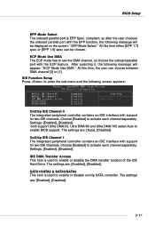
...Enabled] to enable or disable the DMA transfer function of the IDE Hard Drive. SATA1/SATA2 & SATA3/SATA4 This item is used to enable BIOS support. After selecting it, the following message will appear: "ECP Mode Use DMA." The settings are : [Enabled], [Disabled]. Choose [Enabled...] to enter the sub-menu and the following screen appears: OnChip IDE Channel 0 The integrated peripheral controller contains an IDE interface with the EPP function, the following message will be chosen. Settings: [...
...Enabled] to enable or disable the DMA transfer function of the IDE Hard Drive. SATA1/SATA2 & SATA3/SATA4 This item is used to enable BIOS support. After selecting it, the following message will appear: "ECP Mode Use DMA." The settings are : [Enabled], [Disabled]. Choose [Enabled...] to enter the sub-menu and the following screen appears: OnChip IDE Channel 0 The integrated peripheral controller contains an IDE interface with the EPP function, the following message will be chosen. Settings: [...
User Guide
Page 60
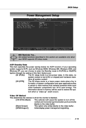
... cause the system to turn off the vertical and horizontal synchronization ports and write blanks to the video buffer. [Blank Screen] This option only writes blanks to save energy. If your BIOS supports S3 sleep mode. S3-related functions described in formation of this section are : [S1 (POS)] The S1 sleep ...chipset) and hardware maintains all system context. [S3 (STR)] The S3 sleep mode is a lower power state where the in this field. Power Management Setup BIOS Setup MSI Reminds You... ACPI Standby State This item specifies the power saving modes for ACPI function.
... cause the system to turn off the vertical and horizontal synchronization ports and write blanks to the video buffer. [Blank Screen] This option only writes blanks to save energy. If your BIOS supports S3 sleep mode. S3-related functions described in formation of this section are : [S1 (POS)] The S1 sleep ...chipset) and hardware maintains all system context. [S3 (STR)] The S3 sleep mode is a lower power state where the in this field. Power Management Setup BIOS Setup MSI Reminds You... ACPI Standby State This item specifies the power saving modes for ACPI function.
User Guide
Page 70
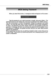
... abort the selection and not enter a password. The password typed now will replace any previously set password from changing any password. BIOS Setup BIOS Setting Password When you select this function, a message as below will appear on the screen: Type the password, up confirming the password will be prompted to enter the password.
... abort the selection and not enter a password. The password typed now will replace any previously set password from changing any password. BIOS Setup BIOS Setting Password When you select this function, a message as below will appear on the screen: Type the password, up confirming the password will be prompted to enter the password.

User Guide
Page 79
... purchased does not support any of the screen. Click the desired button to search for the correct BIOS/driver version throughout the whole Web site. Live BIOS - Updates the BIOS online. Updates the VGA BIOS online. Updates the firmware of the OSD products online. After the installation, the "MSI Live Update 3" icon (as shown on the...
... purchased does not support any of the screen. Click the desired button to search for the correct BIOS/driver version throughout the whole Web site. Live BIOS - Updates the BIOS online. Updates the VGA BIOS online. Updates the firmware of the OSD products online. After the installation, the "MSI Live Update 3" icon (as shown on the...
User Guide
Page 97
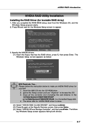
...Enter. (4) Select "NVIDIA NForce Storage Controller" and then pressEnter. The driver disk for the Windows Setup screen to make an nVIDIA RAID driver for bootable RAID Array) 1. Insert the MSI CD into the CD-ROM drive. 2. Copy all the contents (not including the sub-folders) in ...floppy that has the RAID driver, press S, then press Enter. Ignore the Setup screen and use "Explorer" to a formatted floppy disk. 4. The Windows Setup screen appears as below to appear. 3. After you complete the RAID BIOS setup, boot from the Windows CD, and the Windows Setup program starts. 2. ...
...Enter. (4) Select "NVIDIA NForce Storage Controller" and then pressEnter. The driver disk for the Windows Setup screen to make an nVIDIA RAID driver for bootable RAID Array) 1. Insert the MSI CD into the CD-ROM drive. 2. Copy all the contents (not including the sub-folders) in ...floppy that has the RAID driver, press S, then press Enter. Ignore the Setup screen and use "Explorer" to a formatted floppy disk. 4. The Windows Setup screen appears as below to appear. 3. After you complete the RAID BIOS setup, boot from the Windows CD, and the Windows Setup program starts. 2. ...
User Guide
Page 117
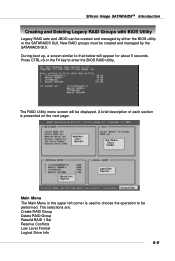
...presented on the next page. The RAID Utility menu screen will appear for about 5 seconds. During boot up, a screen similar to enter the BIOS RAID utility. New RAID groups must be created and managed by either the BIOS utility or the SATARAID5 GUI. Silicon Image SATARAID5TM Introduction... Creating and Deleting Legacy RAID Groups with BIOS Utility Legacy RAID sets and JBOD...
...presented on the next page. The RAID Utility menu screen will appear for about 5 seconds. During boot up, a screen similar to enter the BIOS RAID utility. New RAID groups must be created and managed by either the BIOS utility or the SATARAID5 GUI. Silicon Image SATARAID5TM Introduction... Creating and Deleting Legacy RAID Groups with BIOS Utility Legacy RAID sets and JBOD...


