User Guide
Page 4
... or local distributor. If any of the following help resources for further guidance. † Visit the MSI homepage & FAQ site for technical guide, BIOS updates, driver updates, and other information: http://www.msi.com.tw & http://www.msi. iv ment from humidity. 4. Place the power cord such a way that could damage or cause electrical... the user's manual, please contact your place of breakage. 12. com.tw/program/service/faq/faq/esc_faq_list.php † Contact our technical staff at: support@msi.com.tw Safety Instructions 1.
... or local distributor. If any of the following help resources for further guidance. † Visit the MSI homepage & FAQ site for technical guide, BIOS updates, driver updates, and other information: http://www.msi.com.tw & http://www.msi. iv ment from humidity. 4. Place the power cord such a way that could damage or cause electrical... the user's manual, please contact your place of breakage. 12. com.tw/program/service/faq/faq/esc_faq_list.php † Contact our technical staff at: support@msi.com.tw Safety Instructions 1.

User Guide
Page 6
... 3-12 Power Management Setup 3-17 PNP/PCI Configurations 3-20 H/W Monitor ...3-22 Cell Menu ...3-23 Load Fail-Safe/Optimized Defaults 3-30 BIOS Setting Password 3-31 Chapter 4. Introduction to DigiCell 4-1 Main ...4-2 H/W Diagnostic ...4-4 Communication ...4-5 Software Access Point 4-6 Terminology 4-6 Access Point...WLAN Card Mode 4-8 Live Update ...4-9 MEGA STICK ...4-10 Basic Function 4-10 Non-Unicode programs supported 4-12 Core Center (for AMD K8 Processor 4-14 vi IrDA Infrared Module Header: JIR1 2-20 IEEE 1394 Connectors: J1394_1 (Optional 2-21 D-BracketTM 2 Connector...
... 3-12 Power Management Setup 3-17 PNP/PCI Configurations 3-20 H/W Monitor ...3-22 Cell Menu ...3-23 Load Fail-Safe/Optimized Defaults 3-30 BIOS Setting Password 3-31 Chapter 4. Introduction to DigiCell 4-1 Main ...4-2 H/W Diagnostic ...4-4 Communication ...4-5 Software Access Point 4-6 Terminology 4-6 Access Point...WLAN Card Mode 4-8 Live Update ...4-9 MEGA STICK ...4-10 Basic Function 4-10 Non-Unicode programs supported 4-12 Core Center (for AMD K8 Processor 4-14 vi IrDA Infrared Module Header: JIR1 2-20 IEEE 1394 Connectors: J1394_1 (Optional 2-21 D-BracketTM 2 Connector...
User Guide
Page 7
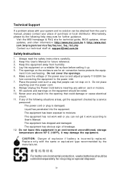
Installation of RAID Configurations 5-2 RAID Configuration 5-3 Basic Configuration Instructions 5-3 Setting Up the NVRAID BIOS 5-3 NVIDIA RAID Untility Installation 5-7 Installing the RAID Driver (for bootable RAID Array 5-7 Installing the NVIDIA RAID Software Under W indows (for Non-bootable RAID Array 5-9 Initializing ...
Installation of RAID Configurations 5-2 RAID Configuration 5-3 Basic Configuration Instructions 5-3 Setting Up the NVRAID BIOS 5-3 NVIDIA RAID Untility Installation 5-7 Installing the RAID Driver (for bootable RAID Array 5-7 Installing the NVIDIA RAID Software Under W indows (for Non-bootable RAID Array 5-9 Initializing ...

User Guide
Page 11
... SPDIF out - 1 coaxial SPDIF out - 1 IrDA pinheader - 1 CD-In pinheader - 1 D-Bracket2 pinheader - 2 IEEE1394 ports (Rear * 1 / Front * 1)(Optional) - 10 USB1.1/2.0 ports (Rear * 4 / Front * 6) BIOS † The mainboard BIOS provides "Plug & Play" BIOS which detects the peripheral devices and expansion cards of the board automatically. † The mainboard provides a Desktop Management Interface (DMI) function which...
... SPDIF out - 1 coaxial SPDIF out - 1 IrDA pinheader - 1 CD-In pinheader - 1 D-Bracket2 pinheader - 2 IEEE1394 ports (Rear * 1 / Front * 1)(Optional) - 10 USB1.1/2.0 ports (Rear * 4 / Front * 6) BIOS † The mainboard BIOS provides "Plug & Play" BIOS which detects the peripheral devices and expansion cards of the board automatically. † The mainboard provides a Desktop Management Interface (DMI) function which...
User Guide
Page 31
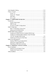
... opened, the switch will record this status and show a warning message on cable, you must enter the BIOS utility and clear the record. You must configure the second drive to a 2-pin chassis switch. MSI Reminds You... If you install two hard disks on the screen. If the chassis is connected to Slave...
... opened, the switch will record this status and show a warning message on cable, you must enter the BIOS utility and clear the record. You must configure the second drive to a 2-pin chassis switch. MSI Reminds You... If you install two hard disks on the screen. If the chassis is connected to Slave...

User Guide
Page 34
.... 6 10 59 IrDA Infrared Module Header: JIR1 The connector allows you to connect to the rear audio ports. You must configure the setting through the BIOS setup to use to control headphone amplifier No pin Left channel audio signal to front panel Left channel audio signal return from front panel... MSI Reminds You... If you don't want to connect to the front audio header, pins 5 & 6, 9 & 10 have to be jumpered in order to have signal output ...
.... 6 10 59 IrDA Infrared Module Header: JIR1 The connector allows you to connect to the rear audio ports. You must configure the setting through the BIOS setup to use to control headphone amplifier No pin Left channel audio signal to front panel Left channel audio signal return from front panel... MSI Reminds You... If you don't want to connect to the front audio header, pins 5 & 6, 9 & 10 have to be jumpered in order to have signal output ...

User Guide
Page 37
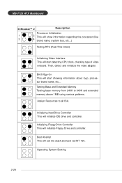
Early Chipset Initialization Memory Detection Test Testing onboard memory size. Decompressing BIOS image to debug the system. Initializing Keyboard Controller. Hardware Setup D-Bracket™ 2 is damaged or not installed properly. The D-LED will hang if the memory .... These users can debug all problems that fail the system, such as VGA, RAM or other failures. D-Bracket™ 2 supports both USB 1.1 & 2.0 specification. Testing VGA BIOS This will hang here if the processor is very useful for fast booting.
Early Chipset Initialization Memory Detection Test Testing onboard memory size. Decompressing BIOS image to debug the system. Initializing Keyboard Controller. Hardware Setup D-Bracket™ 2 is damaged or not installed properly. The D-LED will hang if the memory .... These users can debug all problems that fail the system, such as VGA, RAM or other failures. D-Bracket™ 2 supports both USB 1.1 & 2.0 specification. Testing VGA BIOS This will hang here if the processor is very useful for fast booting.
User Guide
Page 38
Initializing Hard Drive Controller This will set low stack and boot via INT 19h. BIOS Sign On This will start detecting CPU clock, checking type of video onboard. Testing Base and Extended Memory Testing base memory from 240K to all ...
Initializing Hard Drive Controller This will set low stack and boot via INT 19h. BIOS Sign On This will start detecting CPU clock, checking type of video onboard. Testing Base and Extended Memory Testing base memory from 240K to all ...

User Guide
Page 40
PCI Express Slots The PCI Express slots, as jumpers, switches or BIOS configuration. W hen adding or removing expansion cards, make sure that you to deliver highest performance in video, graphics, multimedia and other sophisticated applications. The orange ...
PCI Express Slots The PCI Express slots, as jumpers, switches or BIOS configuration. W hen adding or removing expansion cards, make sure that you to deliver highest performance in video, graphics, multimedia and other sophisticated applications. The orange ...

User Guide
Page 42
MSI Reminds You... 1. It is usually in this BIOS is shown in the 1st line appearing after the memory counting. V1.0 refers to the BIOS version. 061704 refers to run the Setup program when: ” An error message appears on the screen during the system booting up , the BIOS version is ...6th digit refers to nVIDIA chipset. 7th - 8th digit refers to configure the system for reference only. 2. BIOS Setup BIOS Setup This chapter provides information on the BIOS Setup program and allows you to the date this chapter are under continuous update for customized features. Therefore, the...
MSI Reminds You... 1. It is usually in this BIOS is shown in the 1st line appearing after the memory counting. V1.0 refers to the BIOS version. 061704 refers to run the Setup program when: ” An error message appears on the screen during the system booting up , the BIOS version is ...6th digit refers to nVIDIA chipset. 7th - 8th digit refers to configure the system for reference only. 2. BIOS Setup BIOS Setup This chapter provides information on the BIOS Setup program and allows you to the date this chapter are under continuous update for customized features. Therefore, the...

User Guide
Page 43
...described in time. When the message below appears on the screen, press to select the 1st boot device without entering the BIOS setup utility by simultaneously pressing , , and keys. Select First Boot Device Floppy IDE-0 CDROM : 1st Floppy : IBM...cancel The boot menu will boot from the selected device. The selection will not make changes to the settings in the BIOS setup utility, so next time when you to respond in this chapter are allowed to trigger the boot menu. The POST... Setup Power on the system, it OFF and On or pressing the RESET button. MSI Reminds You...
...described in time. When the message below appears on the screen, press to select the 1st boot device without entering the BIOS setup utility by simultaneously pressing , , and keys. Select First Boot Device Floppy IDE-0 CDROM : 1st Floppy : IBM...cancel The boot menu will boot from the selected device. The selection will not make changes to the settings in the BIOS setup utility, so next time when you to respond in this chapter are allowed to trigger the boot menu. The POST... Setup Power on the system, it OFF and On or pressing the RESET button. MSI Reminds You...
User Guide
Page 44
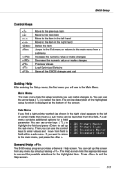
... keys to use the arrow keys ( ↑↓ ) to select the item. You can use and the possible selections for a field parameter. General Help The BIOS setup program provides a General Help screen. You can call up this field. Press to the main menu, just press the... . BIOS Setup Control Keys Enter> Move to the previous item Move to the next item Move to the item in the right hand Select the item ...
... keys to use the arrow keys ( ↑↓ ) to select the item. You can use and the possible selections for a field parameter. General Help The BIOS setup program provides a General Help screen. You can call up this field. Press to the main menu, just press the... . BIOS Setup Control Keys Enter> Move to the previous item Move to the next item Move to the item in the right hand Select the item ...
User Guide
Page 45
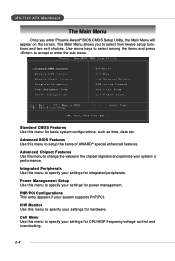
.... Advanced Chipset Features Use this menu to setup the items of AWARD® special enhanced features. The Main Menu allows you enter Phoenix-Award® BIOS CMOS Setup Utility, the Main Menu will appear on the screen. Advanced BIOS Features Use this menu to specify your system supports PnP/PCI.
.... Advanced Chipset Features Use this menu to setup the items of AWARD® special enhanced features. The Main Menu allows you enter Phoenix-Award® BIOS CMOS Setup Utility, the Main Menu will appear on the screen. Advanced BIOS Features Use this menu to specify your system supports PnP/PCI.
User Guide
Page 46
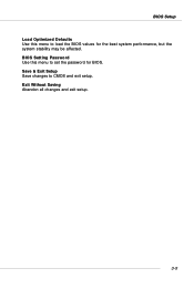
BIOS Setting Password Use this menu to load the BIOS values for BIOS. Exit Without Saving Abandon all changes and exit setup. 3-5 Save & Exit Setup Save changes to CMOS and exit setup. BIOS Setup Load Optimized Defaults Use this menu to set the password for the best system performance, but the system stability may be affected.
BIOS Setting Password Use this menu to load the BIOS values for BIOS. Exit Without Saving Abandon all changes and exit setup. 3-5 Save & Exit Setup Save changes to CMOS and exit setup. BIOS Setup Load Optimized Defaults Use this menu to set the password for the best system performance, but the system stability may be affected.

User Guide
Page 47
.... Use the arrow keys to highlight the item and then use [Manual] to the following items. Enter the information directly from 1 to Sat, determined by BIOS. Date This allows you to set the system time that the specifications of the week, from Jan. Note that you enter improper information for this...
.... Use the arrow keys to highlight the item and then use [Manual] to the following items. Enter the information directly from 1 to Sat, determined by BIOS. Date This allows you to set the system time that the specifications of the week, from Jan. Note that you enter improper information for this...
User Guide
Page 48
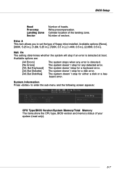
... type of floppy drive installed. The system doesn't stop for a keyboard error. The system doesn't stop if an error is detected. BIOS Setup Head Precomp Landing Zone Sector Number of sectors. Cylinder location of your system (read only). 3-7 Write precompensation. Drive A This item... allows you to enter the sub-menu and the following screen appears: CPU Type/BIOS Version/System Memory/Total Memory The items show the CPU type, BIOS version and memory status of the landing zone. Available options: [None], [360K, 5.25 in.], [1.2M, 5.25...
... type of floppy drive installed. The system doesn't stop for a keyboard error. The system doesn't stop if an error is detected. BIOS Setup Head Precomp Landing Zone Sector Number of sectors. Cylinder location of your system (read only). 3-7 Write precompensation. Drive A This item... allows you to enter the sub-menu and the following screen appears: CPU Type/BIOS Version/System Memory/Total Memory The items show the CPU type, BIOS version and memory status of the landing zone. Available options: [None], [360K, 5.25 in.], [1.2M, 5.25...
User Guide
Page 49
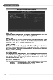
... operating system. Full Screen LOGO Display This item enables you to select the MPS version supported by your operating system. MS-7125 ATX Mainboard Advanced BIOS Features Quick Boot Setting the item to [Enabled] allows the system to boot within 5 seconds since it is possible if you choose [Yes]. When you...
... operating system. Full Screen LOGO Display This item enables you to select the MPS version supported by your operating system. MS-7125 ATX Mainboard Advanced BIOS Features Quick Boot Setting the item to [Enabled] allows the system to boot within 5 seconds since it is possible if you choose [Yes]. When you...
User Guide
Page 50
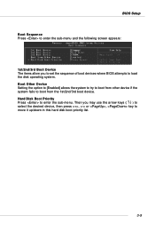
... to load the disk operating system. Hard Disk Boot Priority Press to boot from other device if the system fails to enter the sub-menu. BIOS Setup Boot Sequence Press to enter the sub-menu and the following screen appears: 1st/2nd/3rd Boot Device The items allow you may use...
... to load the disk operating system. Hard Disk Boot Priority Press to boot from other device if the system fails to enter the sub-menu. BIOS Setup Boot Sequence Press to enter the sub-menu and the following screen appears: 1st/2nd/3rd Boot Device The items allow you may use...
User Guide
Page 52
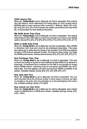
... timing of cycles for the RAS to accumulate its charge before SDRAM starts a read from and write to a memory cell. Available settings: [Auto], [7T]~[22T]. BIOS Setup CAS# Latency (Tcl) When the Timing Mode is set to [Manual], the field is adjustable.This controls the CAS latency, which determines the timing...
... timing of cycles for the RAS to accumulate its charge before SDRAM starts a read from and write to a memory cell. Available settings: [Auto], [7T]~[22T]. BIOS Setup CAS# Latency (Tcl) When the Timing Mode is set to [Manual], the field is adjustable.This controls the CAS latency, which determines the timing...

User Guide
Page 54
... in 64-bit OS) Setting options: [Disabled], [Enabled]. Setting options: [2ns], [3ns], [4ns], [5ns], [6ns], [7ns], [8ns], [9ns], [10ns], [11ns]. Setting options: [Discrete], [Continuous]. 3-13 BIOS Setup Read Preamble value When the User Config mode is set to [Manual], the field is adjustable. The controller will disable its DQS receiver while...
... in 64-bit OS) Setting options: [Disabled], [Enabled]. Setting options: [2ns], [3ns], [4ns], [5ns], [6ns], [7ns], [8ns], [9ns], [10ns], [11ns]. Setting options: [Discrete], [Continuous]. 3-13 BIOS Setup Read Preamble value When the User Config mode is set to [Manual], the field is adjustable. The controller will disable its DQS receiver while...


