
User Guide
Page 6
......2-26 PCI Express Slots 2-26 PCI (Peripheral Component Interconnect) Slots 2-26 PCI Interrupt Request Routing 2-27 Chapter 3. BIOS Setup 3-1 Entering Setup ...3-2 Selecting the First Boot Device 3-2 Control Keys 3-3 Getting Help 3-3 The Main Menu ...3-4 Standard CMOS Features 3-6 Advanced BIOS Features 3-8 Advanced Chipset Features 3-11 Integrated Peripherals 3-12 Power Management ...Terminology 4-6 Access Point Mode 4-7 WLAN Card Mode 4-8 Live Update ...4-9 MEGA STICK ...4-10 Basic Function 4-10 Non-Unicode programs supported 4-12 Core Center (for AMD K8 Processor 4-14 vi
......2-26 PCI Express Slots 2-26 PCI (Peripheral Component Interconnect) Slots 2-26 PCI Interrupt Request Routing 2-27 Chapter 3. BIOS Setup 3-1 Entering Setup ...3-2 Selecting the First Boot Device 3-2 Control Keys 3-3 Getting Help 3-3 The Main Menu ...3-4 Standard CMOS Features 3-6 Advanced BIOS Features 3-8 Advanced Chipset Features 3-11 Integrated Peripherals 3-12 Power Management ...Terminology 4-6 Access Point Mode 4-7 WLAN Card Mode 4-8 Live Update ...4-9 MEGA STICK ...4-10 Basic Function 4-10 Non-Unicode programs supported 4-12 Core Center (for AMD K8 Processor 4-14 vi

User Guide
Page 11
... peripheral devices and expansion cards of the board automatically. † The mainboard provides a Desktop Management Interface (DMI) function which records your mainboard specifications. † Supports boot from LAN, USB Device 1.1 & 2.0, and SATA HDD. 1-3 RAID 0 or 1, 0+1, JBOD is up to two 1394 ports (rear panel x 1, pinheader x 1). Transfer rate is supported...
... peripheral devices and expansion cards of the board automatically. † The mainboard provides a Desktop Management Interface (DMI) function which records your mainboard specifications. † Supports boot from LAN, USB Device 1.1 & 2.0, and SATA HDD. 1-3 RAID 0 or 1, 0+1, JBOD is up to two 1394 ports (rear panel x 1, pinheader x 1). Transfer rate is supported...

User Guide
Page 12
... operating system onto the bootable RAID volume. M S-7125 ATX M ainboard † Supports boot from LAN, USB Device 1.1 & 2.0, and SATA HDD. As the end user cannot boot without SP4, a combination installation CD must be created before attempting to the following website: ...http://www.microsoft.com/windows2000/downloads/ servicepacks/sp4/HFdeploy.htm 1-4 Dimension † ATX Form Factor (30.4 cm X 24.4 cm) Mounting † 9 mounting holes MSI Reminds You... 1.
... operating system onto the bootable RAID volume. M S-7125 ATX M ainboard † Supports boot from LAN, USB Device 1.1 & 2.0, and SATA HDD. As the end user cannot boot without SP4, a combination installation CD must be created before attempting to the following website: ...http://www.microsoft.com/windows2000/downloads/ servicepacks/sp4/HFdeploy.htm 1-4 Dimension † ATX Form Factor (30.4 cm X 24.4 cm) Mounting † 9 mounting holes MSI Reminds You... 1.
User Guide
Page 25
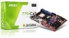
... about Power Issue NForce chipset is very sensitive to ESD (Electrostatic Discharge), therefore this kind of memory-replacement actions might cause system chipset unable to boot. Due to several pins are very sensitive to avoid this situation. Please follow the following solution to ESD, so this issue mostly happens while the...
... about Power Issue NForce chipset is very sensitive to ESD (Electrostatic Discharge), therefore this kind of memory-replacement actions might cause system chipset unable to boot. Due to several pins are very sensitive to avoid this situation. Please follow the following solution to ESD, so this issue mostly happens while the...

User Guide
Page 37
... or failures. D-Bracket™ 2 1 2 3 4 Red Green D-Bracket™ 2 Description System Power ON 1 2 The D-LED will hang here if the processor is very useful for fast booting. Initializing Keyboard Controller.
... or failures. D-Bracket™ 2 1 2 3 4 Red Green D-Bracket™ 2 Description System Power ON 1 2 The D-LED will hang here if the processor is very useful for fast booting. Initializing Keyboard Controller.
User Guide
Page 38
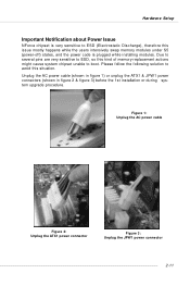
BIOS Sign On This will start detecting CPU clock, checking type of video onboard. Operating System Booting 2-24 Assign Resources to 640K and extended memory above 1MB using various patterns. Then, detect and initialize the ... Initializing Floppy Drive Controller This will initialize IDE drive and controller. Initializing Hard Drive Controller This will initialize Floppy Drive and controller. Boot Attempt This will set low stack and boot via INT 19h. M S-7125 ATX M ainboard D-Bracket™ 2 Description Processor Initialization 1 2 This will show information regarding ...
BIOS Sign On This will start detecting CPU clock, checking type of video onboard. Operating System Booting 2-24 Assign Resources to 640K and extended memory above 1MB using various patterns. Then, detect and initialize the ... Initializing Floppy Drive Controller This will initialize IDE drive and controller. Initializing Hard Drive Controller This will initialize Floppy Drive and controller. Boot Attempt This will set low stack and boot via INT 19h. M S-7125 ATX M ainboard D-Bracket™ 2 Description Processor Initialization 1 2 This will show information regarding ...

User Guide
Page 39
W ith the CMOS RAM, the system can automatically boot OS every time it is a CMOS RAM on . Press the button in the middle of button. If you to set the computer's function. SW1 2-25 Hardware Setup Button The motherboard provides the following button for you want to clear the system configuration, use of... is turned on board that has a power supply from external battery to keep the system configuration data. This section will explain how to change your motherboard's function through the use the SW 1 (Clear CMOS Button ) to clear the data.
W ith the CMOS RAM, the system can automatically boot OS every time it is a CMOS RAM on . Press the button in the middle of button. If you to set the computer's function. SW1 2-25 Hardware Setup Button The motherboard provides the following button for you want to clear the system configuration, use of... is turned on board that has a power supply from external battery to keep the system configuration data. This section will explain how to change your motherboard's function through the use the SW 1 (Clear CMOS Button ) to clear the data.

User Guide
Page 42
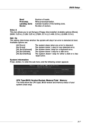
V1.0 refers to the BIOS version. 061704 refers to configure the system for customized features. While booting up , and requests you to the date this chapter are under each BIOS category described in the format: example: W7125NMS V1.0B32 061704 where: 1st ... refers to nVIDIA chipset. 7th - 8th digit refers to run the Setup program when: ” An error message appears on the screen during the system booting up , the BIOS version is released. 3-1 You may be slightly different from the latest BIOS and should be held for better system performance...
V1.0 refers to the BIOS version. 061704 refers to configure the system for customized features. While booting up , and requests you to the date this chapter are under each BIOS category described in the format: example: W7125NMS V1.0B32 061704 where: 1st ... refers to nVIDIA chipset. 7th - 8th digit refers to run the Setup program when: ” An error message appears on the screen during the system booting up , the BIOS version is released. 3-1 You may be slightly different from the latest BIOS and should be held for better system performance...

User Guide
Page 43
... also restart the system by using arrow keys, then press . Press DEL to enter SETUP If the message disappears before you respond and you to boot from by simultaneously pressing , , and keys. The POST messages might pass by too quickly for reference only. 3-2 Select the one you power on... the screen, press to enter Setup, restart the system by pressing . MSI Reminds You... Select First Boot Device Floppy IDE-0 CDROM : 1st Floppy : IBM-DTLA-307038 : ATAPI CD-ROM DRIVE 40X M [Up/Dn] Select [RETURN...
... also restart the system by using arrow keys, then press . Press DEL to enter SETUP If the message disappears before you respond and you to boot from by simultaneously pressing , , and keys. The POST messages might pass by too quickly for reference only. 3-2 Select the one you power on... the screen, press to enter Setup, restart the system by pressing . MSI Reminds You... Select First Boot Device Floppy IDE-0 CDROM : 1st Floppy : IBM-DTLA-307038 : ATAPI CD-ROM DRIVE 40X M [Up/Dn] Select [RETURN...
User Guide
Page 48
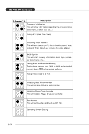
... will stop for a disk error. The system doesn't stop for either a disk or a keyboard error. The system doesn'tstop for any error is detected at boot. The system doesn't stop if an error is detected. System Information Press to set the type of heads. Drive A This item allows you to enter...
... will stop for a disk error. The system doesn't stop for either a disk or a keyboard error. The system doesn'tstop for any error is detected at boot. The system doesn't stop if an error is detected. System Information Press to set the type of heads. Drive A This item allows you to enter...
User Guide
Page 49
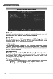
... Interrupt Controller). Full Screen LOGO Display This item enables you to show the company logo on the full screen at boot. [Disabled] Shows the POST messages at boot. 3-8 But it will expand available IRQ resources for the operating system. Settings: [Enabled], [Disabled]. You need to...the MPS version supported by your operating system. Settings: [1.4], [1.1]. Settings are: [Enabled] Shows a still image (logo) on the bootup screen. Boot To OS/2 This allows you to run the OS/2® operating system with PC2001 design guide, the system is able to run the OS/2®...
... Interrupt Controller). Full Screen LOGO Display This item enables you to show the company logo on the full screen at boot. [Disabled] Shows the POST messages at boot. 3-8 But it will expand available IRQ resources for the operating system. Settings: [Enabled], [Disabled]. You need to...the MPS version supported by your operating system. Settings: [1.4], [1.1]. Settings are: [Enabled] Shows a still image (logo) on the bootup screen. Boot To OS/2 This allows you to run the OS/2® operating system with PC2001 design guide, the system is able to run the OS/2®...
User Guide
Page 50
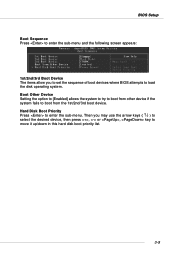
... the option to [Enabled] allows the system to try to boot from the 1st/2nd/3rd boot device. Hard Disk Boot Priority Press to boot from other device if the system fails to enter the sub-menu. Then you to set the sequence of boot devices where BIOS attempts to load the disk operating system.... BIOS Setup Boot Sequence Press to enter the sub-menu and the following screen appears: 1st/2nd/3rd Boot Device The items allow you may use the arrow keys ( ↑...
... the option to [Enabled] allows the system to try to boot from the 1st/2nd/3rd boot device. Hard Disk Boot Priority Press to boot from other device if the system fails to enter the sub-menu. Then you to set the sequence of boot devices where BIOS attempts to load the disk operating system.... BIOS Setup Boot Sequence Press to enter the sub-menu and the following screen appears: 1st/2nd/3rd Boot Device The items allow you may use the arrow keys ( ↑...

User Guide
Page 56
... device is used. COM Port 1 Select an address and corresponding interrupt for serial port 2. Onboard GigaBit LAN ROM This setting controls the onboard Marvell LAN Boot ROM. The settings are: [Auto], [Disabled]. BIOS Setup Onboard GigaBit LAN Setting to [Enabled] allows the BIOS to detect the Marvell LAN controller and enable...
... device is used. COM Port 1 Select an address and corresponding interrupt for serial port 2. Onboard GigaBit LAN ROM This setting controls the onboard Marvell LAN Boot ROM. The settings are: [Auto], [Disabled]. BIOS Setup Onboard GigaBit LAN Setting to [Enabled] allows the BIOS to detect the Marvell LAN controller and enable...
User Guide
Page 61
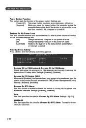
... turned off state. [On] Always leaves the computer in the power off . MS-7125 ATX Mainboard Power Button Function This feature sets the function of booting up the system from the power saving modes through any event on a scheduled time/date. Resume S3 by PS2/Keyboard, Resume S3 by PS2/Mouse...
... turned off state. [On] Always leaves the computer in the power off . MS-7125 ATX Mainboard Power Button Function This feature sets the function of booting up the system from the power saving modes through any event on a scheduled time/date. Resume S3 by PS2/Keyboard, Resume S3 by PS2/Mouse...
User Guide
Page 62
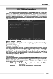
... allows I/O devices to the default settings. However, this field (a sub menu is preceded by going into each IRQ a type depending on the type of the boot and Plug and Play compatible devices. Resource Controlled By The Award Plug and Play BIOS has the capacity to [Manual], choose specific resources by a "`"). Press...
... allows I/O devices to the default settings. However, this field (a sub menu is preceded by going into each IRQ a type depending on the type of the boot and Plug and Play compatible devices. Resource Controlled By The Award Plug and Play BIOS has the capacity to [Manual], choose specific resources by a "`"). Press...
User Guide
Page 70
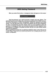
... up confirming the password will appear on the screen: Type the password, up to enter the password. Once the password is disabled, the system will boot and you select this function, a message as below will be prompted to abort the selection and not enter a password. BIOS Setup BIOS Setting Password When...
... up confirming the password will appear on the screen: Type the password, up to enter the password. Once the password is disabled, the system will boot and you select this function, a message as below will be prompted to abort the selection and not enter a password. BIOS Setup BIOS Setting Password When...
User Guide
Page 90
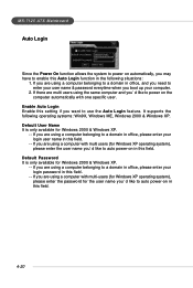
... belonging to a domain in office, please enter your login user name in office, and you need to enter your user name & password everytime when you boot up your login password in this field. 4-20 Default Password It is only available for Windows 2000 & Windows XP. -- Default User Name It is only...
... belonging to a domain in office, please enter your login user name in office, and you need to enter your user name & password everytime when you boot up your login password in this field. 4-20 Default Password It is only available for Windows 2000 & Windows XP. -- Default User Name It is only...

User Guide
Page 93
... enable the IDE RAID or SATA RAID items in RAID Config of the array. The RAID prompt appears as part of the system POST and boot process prior to make part of Integrated Peripherals in BIOS before configuring the NVRAID BIOS. Define a New Array window will reboot right away. NVRAID... which hard drives you to be RAID enabled in the system BIOS. 2. Initialize the NVRAID Array Disks. Press F10, and the NVIDIA RAID Utility --- Boot from the Windows CD, use the floppy disk that are to save the configuration and exit. Initialize the NVRAID Array Disks. The default RAID Mode...
... enable the IDE RAID or SATA RAID items in RAID Config of the array. The RAID prompt appears as part of the system POST and boot process prior to make part of Integrated Peripherals in BIOS before configuring the NVRAID BIOS. Define a New Array window will reboot right away. NVRAID... which hard drives you to be RAID enabled in the system BIOS. 2. Initialize the NVRAID Array Disks. Press F10, and the NVIDIA RAID Utility --- Boot from the Windows CD, use the floppy disk that are to save the configuration and exit. Initialize the NVRAID Array Disks. The default RAID Mode...
User Guide
Page 97
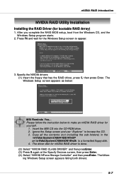
... into the CD-ROM drive. 2. The following Windows Setup screen appears listing both drivers: 5-7 Please follow the instruction below : MSI Reminds You... Specify the NVIDIA drivers: (1) Insert the floppy that has the RAID driver, press S, then press Enter. The Windows Setup screen appears...-folders) in the \\nVidia\System\CK804\IDE\WinXP or \\nVidia\System\CK804\IDE\Win2k to browse the CD. 3. After you complete the RAID BIOS setup, boot from the Windows CD, and the Windows Setup program starts. 2. Ignore the Setup screen and use "Explorer" to a formatted floppy disk. 4. Press F6...
... into the CD-ROM drive. 2. The following Windows Setup screen appears listing both drivers: 5-7 Please follow the instruction below : MSI Reminds You... Specify the NVIDIA drivers: (1) Insert the floppy that has the RAID driver, press S, then press Enter. The Windows Setup screen appears...-folders) in the \\nVidia\System\CK804\IDE\WinXP or \\nVidia\System\CK804\IDE\Win2k to browse the CD. 3. After you complete the RAID BIOS setup, boot from the Windows CD, and the Windows Setup program starts. 2. Ignore the Setup screen and use "Explorer" to a formatted floppy disk. 4. Press F6...

User Guide
Page 104
... mark a disk as free, or not a part of the NVRAIDMAN display if you have a system with four hard disks where one disk is used to boot the OS, two hard drives are set up as a free disk, then if one free disk. 5-14 The drive appears under the Free Disk section... RAID 0+1 array. MS-7125 ATX Mainboard Setting Up a Spare RAID Disk You can designate a hard drive to be used as a spare drive for a failed disk. Boot into Windows and run the NVRAIDMAN program. The spare drive can take over for a RAID 1 or RAID 0+1 array2. Enter the system BIOS setup and make...
... mark a disk as free, or not a part of the NVRAIDMAN display if you have a system with four hard disks where one disk is used to boot the OS, two hard drives are set up as a free disk, then if one free disk. 5-14 The drive appears under the Free Disk section... RAID 0+1 array. MS-7125 ATX Mainboard Setting Up a Spare RAID Disk You can designate a hard drive to be used as a spare drive for a failed disk. Boot into Windows and run the NVRAIDMAN program. The spare drive can take over for a RAID 1 or RAID 0+1 array2. Enter the system BIOS setup and make...


