User Guide
Page 3
Our products are under continual improvement and we reserve the right to the correctness of AMD Corporation. Trademarks All trademarks are registered trademarks of its contents. Revision History Revision V1.0 V1.1 Revision History Date First release for ...nVidia nForce4 Ultra First release for PCB 1.X January 2005 with nVidia nForce4 Ultra/Standard iii AMD, Athlon™, Athlon™ XP, Thoroughbred™, and Duron™ are the properties of the Personal Computer Memory Card International Association. W indows® 98/2000/NT/ XP are registered trademarks of ...
Our products are under continual improvement and we reserve the right to the correctness of AMD Corporation. Trademarks All trademarks are registered trademarks of its contents. Revision History Revision V1.0 V1.1 Revision History Date First release for ...nVidia nForce4 Ultra First release for PCB 1.X January 2005 with nVidia nForce4 Ultra/Standard iii AMD, Athlon™, Athlon™ XP, Thoroughbred™, and Duron™ are the properties of the Personal Computer Memory Card International Association. W indows® 98/2000/NT/ XP are registered trademarks of ...
User Guide
Page 5
... 1-5 Packing Contents 1-6 Chapter 2. Hardware Setup 2-1 Quick Components Guide 2-2 Central Processing Unit: CPU 2-3 CPU Installation Procedures for Socket 939 2-4 Installing AMD Athlon64 CPU Cooler Set 2-5 Memory ...2-7 Introduction to DDR SDRAM 2-7 DIMM Module Combination 2-7 Recommended Memory Combination List 2-8 Installing DDR Modules 2-9 Power Supply ...2-10 ATX 20-Pin Power Connector: ATX1 2-10 ATX 12V Power Connector...
... 1-5 Packing Contents 1-6 Chapter 2. Hardware Setup 2-1 Quick Components Guide 2-2 Central Processing Unit: CPU 2-3 CPU Installation Procedures for Socket 939 2-4 Installing AMD Athlon64 CPU Cooler Set 2-5 Memory ...2-7 Introduction to DDR SDRAM 2-7 DIMM Module Combination 2-7 Recommended Memory Combination List 2-8 Installing DDR Modules 2-9 Power Supply ...2-10 ATX 20-Pin Power Connector: ATX1 2-10 ATX 12V Power Connector...
User Guide
Page 10
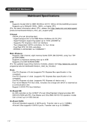
... † Supports a maximum memory size up to 4GB † Supports 2.5v DDR SDRAM DIMM (For the updated supporting memory modules, please visit http://www.msi.com.tw/ program/products/mainboard...up to 300MB/s. 1-2 Two independent SATA controllers, for 1000BASE-T Main Memory † Supports dual channel, eight memory banks DDR 266/333/400, using four 184- Transfer rate is reserved...3500+, 3800+, or higher CPU (For the latest information about CPU, please visit http://www.msi.com.tw/program/ products/mainboard/mbd/pro_mbd_cpu_support.php) Chipset † nVIDIA nForce4 Ultra/Standard - ...
... † Supports a maximum memory size up to 4GB † Supports 2.5v DDR SDRAM DIMM (For the updated supporting memory modules, please visit http://www.msi.com.tw/ program/products/mainboard...up to 300MB/s. 1-2 Two independent SATA controllers, for 1000BASE-T Main Memory † Supports dual channel, eight memory banks DDR 266/333/400, using four 184- Transfer rate is reserved...3500+, 3800+, or higher CPU (For the latest information about CPU, please visit http://www.msi.com.tw/program/ products/mainboard/mbd/pro_mbd_cpu_support.php) Chipset † nVIDIA nForce4 Ultra/Standard - ...
User Guide
Page 15
W hile doing the installation, be careful in holding the components and follow the installation procedures. 2-1 Hardware Setup Chapter 2. Also, it provides the instructions on the mainboard. Hardware Setup Hardware Setup This chapter tells you how to install the CPU, memory modules, and expansion cards, as well as how to setup the jumpers on connecting the peripheral devices, such as the mouse, keyboard, etc.
W hile doing the installation, be careful in holding the components and follow the installation procedures. 2-1 Hardware Setup Chapter 2. Also, it provides the instructions on the mainboard. Hardware Setup Hardware Setup This chapter tells you how to install the CPU, memory modules, and expansion cards, as well as how to setup the jumpers on connecting the peripheral devices, such as the mouse, keyboard, etc.
User Guide
Page 21
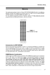
... opposed to the suggested DDR population table below). Hardware Setup Memory The mainboard provides 4 slots for 184-pin DDR SDRAM DIMM (Double In-Line Memory Module) modules and supports the memory size up to 4GB. High memory bandwidth makes DDR an ideal solution for high performance PC, ...are some rules while using dual-channel DDR, or instability may install memory modules of 1GB. or double-sided modules to meet their own needs. For the updated supporting memory modules, please visit http://www.msi.com.tw/ program/products/mainboard/mbd/pro_mbd_trp_list.php. Users can install DDR266...
... opposed to the suggested DDR population table below). Hardware Setup Memory The mainboard provides 4 slots for 184-pin DDR SDRAM DIMM (Double In-Line Memory Module) modules and supports the memory size up to 4GB. High memory bandwidth makes DDR an ideal solution for high performance PC, ...are some rules while using dual-channel DDR, or instability may install memory modules of 1GB. or double-sided modules to meet their own needs. For the updated supporting memory modules, please visit http://www.msi.com.tw/ program/products/mainboard/mbd/pro_mbd_trp_list.php. Users can install DDR266...
User Guide
Page 22
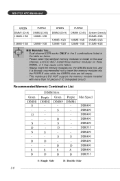
...128MB~1GB 128MB~1GB System Density 256MB~2GB 256MB~2GB 512MB~4GB MSI Reminds You... - Please select the identical memory modules to install on the dual channel, and DO NOT install three memory modules on three DIMMs, or it is strongly recommended not to ... into the GREEN slots first, and it may cause some failure. - Always insert the memory modules into the PURPLE slots while the GREEN slots are left empty. - Recommended Memory Combination List Green DIMM1 S - D - D S D S D S D DIMM Slots Purple Green DIMM2 DIMM3 - - - S - - - S - D S S D D Purple DIMM4 S D S...
...128MB~1GB 128MB~1GB System Density 256MB~2GB 256MB~2GB 512MB~4GB MSI Reminds You... - Please select the identical memory modules to install on the dual channel, and DO NOT install three memory modules on three DIMMs, or it is strongly recommended not to ... into the GREEN slots first, and it may cause some failure. - Always insert the memory modules into the PURPLE slots while the GREEN slots are left empty. - Recommended Memory Combination List Green DIMM1 S - D - D S D S D S D DIMM Slots Purple Green DIMM2 DIMM3 - - - S - - - S - D S S D D Purple DIMM4 S D S...
User Guide
Page 23
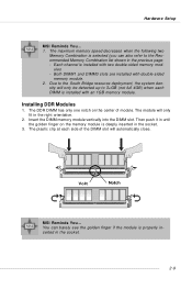
... each side of module. The maximum memory speed decreases when the following two Memory Combination is installed with an 1GB memory module. Both DIMM1 and DIMM3 slots are installed with two double-sided memory mod- Installing DDR Modules 1. Volt Notch MSI Reminds You... You can also refer ...barely see the golden finger if the module is installed with double-sided memory module. 2. Each channel is properly inserted in the previous page: - Hardware Setup MSI Reminds You... 1. Insert the DIMM memory module vertically into the DIMM slot. Then push it in until the golden...
... each side of module. The maximum memory speed decreases when the following two Memory Combination is installed with an 1GB memory module. Both DIMM1 and DIMM3 slots are installed with two double-sided memory mod- Installing DDR Modules 1. Volt Notch MSI Reminds You... You can also refer ...barely see the golden finger if the module is installed with double-sided memory module. 2. Each channel is properly inserted in the previous page: - Hardware Setup MSI Reminds You... 1. Insert the DIMM memory module vertically into the DIMM slot. Then push it in until the golden...
User Guide
Page 25
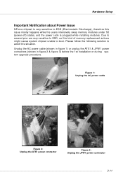
... 1 power connectors (shown in figure 2 & figure 3) before the 1st installation or during system upgrade procedure. Please follow the following solution to avoid this kind of memory-replacement actions might cause system chipset unable to ESD (Electrostatic Discharge), therefore this issue mostly happens while the users intensively swap...
... 1 power connectors (shown in figure 2 & figure 3) before the 1st installation or during system upgrade procedure. Please follow the following solution to avoid this kind of memory-replacement actions might cause system chipset unable to ESD (Electrostatic Discharge), therefore this issue mostly happens while the users intensively swap...

User Guide
Page 37
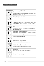
...The D-LED will start writing VGA sign-on message to the screen. 2-23 Testing VGA BIOS This will hang if the memory module is damaged or not installed properly. D-Bracket™ 2 supports both USB 1.1 & 2.0 specification. Decompressing BIOS image to debug ...the system. Early Chipset Initialization Memory Detection Test Testing onboard memory size. Hardware Setup D-Bracket™ 2 is an external USB bracket integrating four Diagnostic LEDs, which use the feature to detect...
...The D-LED will start writing VGA sign-on message to the screen. 2-23 Testing VGA BIOS This will hang if the memory module is damaged or not installed properly. D-Bracket™ 2 supports both USB 1.1 & 2.0 specification. Decompressing BIOS image to debug ...the system. Early Chipset Initialization Memory Detection Test Testing onboard memory size. Hardware Setup D-Bracket™ 2 is an external USB bracket integrating four Diagnostic LEDs, which use the feature to detect...
User Guide
Page 38
... detecting CPU clock, checking type of video onboard. Then, detect and initialize the video adapter. Testing Base and Extended Memory Testing base memory from 240K to all ISA. Assign Resources to 640K and extended memory above 1MB using various patterns. Boot Attempt This will start showing information about logo, processor brand name, etc...
... detecting CPU clock, checking type of video onboard. Then, detect and initialize the video adapter. Testing Base and Extended Memory Testing base memory from 240K to all ISA. Assign Resources to 640K and extended memory above 1MB using various patterns. Boot Attempt This will start showing information about logo, processor brand name, etc...

User Guide
Page 42
... to the date this chapter are under continuous update for reference only. 2. V1.0 refers to the BIOS version. 061704 refers to BIOS maker as A=AMI(R); MSI Reminds You... 1. While booting up , and requests you to configure the system for customized features. Therefore, the description may need to run the Setup program... Setup This chapter provides information on the screen during the system booting up , the BIOS version is usually in the 1st line appearing after the memory counting.
... to the date this chapter are under continuous update for reference only. 2. V1.0 refers to the BIOS version. 061704 refers to BIOS maker as A=AMI(R); MSI Reminds You... 1. While booting up , and requests you to configure the system for customized features. Therefore, the description may need to run the Setup program... Setup This chapter provides information on the screen during the system booting up , the BIOS version is usually in the 1st line appearing after the memory counting.
User Guide
Page 48
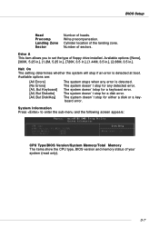
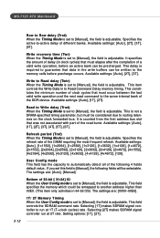
... if an error is detected. Drive A This item allows you to enter the sub-menu and the following screen appears: CPU Type/BIOS Version/System Memory/Total Memory The items show the CPU type, BIOS version and memory status of the landing zone. Cylinder location of your system (read only). 3-7 Write precompensation.
... if an error is detected. Drive A This item allows you to enter the sub-menu and the following screen appears: CPU Type/BIOS Version/System Memory/Total Memory The items show the CPU type, BIOS version and memory status of the landing zone. Cylinder location of your system (read only). 3-7 Write precompensation.

User Guide
Page 51
MS-7125 ATX Mainboard Advanced Chipset Features DRAM Configuration Press to enter the sub-menu and the following fields will be selectable. Please note that memory is set this frequency. If you set to automatically detect all of the DRAM timing. Memclock index value (Mhz) When the Timing Mode is...faster than this field to [Manual], the following screen appears: Timing Mode This field has the capacity to [Manual], user can place an artificial memory clock on the system. The settings are: [Auto], [Manual]. Setting options: [100], [120], [133], [140], [150], [166], [180] [200]. 3-10...
MS-7125 ATX Mainboard Advanced Chipset Features DRAM Configuration Press to enter the sub-menu and the following fields will be selectable. Please note that memory is set this frequency. If you set to automatically detect all of the DRAM timing. Memclock index value (Mhz) When the Timing Mode is...faster than this field to [Manual], the following screen appears: Timing Mode This field has the capacity to [Manual], user can place an artificial memory clock on the system. The settings are: [Auto], [Manual]. Setting options: [100], [120], [133], [140], [150], [166], [180] [200]. 3-10...
User Guide
Page 52
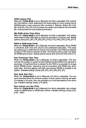
... determine the timing of the transition from row activation up to the precharging of the active row. This item controls the number of clock cycles a memory row takes to complete a full cycle, from RAS (row address strobe) to CAS (column address strobe). Available settings: [Auto], [2T], [3T], ... (Tcl) When the Timing Mode is set to [Manual], the field is adjustable. Row Precharge Time (Trp) When the Timing Mode is set to a memory cell. Available settings: [Auto], [7T]~[22T]. The less the clock cycles, the faster the DRAM performance. Settings: [Auto], [CL=2.0], [CL=2.5], [CL...
... determine the timing of the transition from row activation up to the precharging of the active row. This item controls the number of clock cycles a memory row takes to complete a full cycle, from RAS (row address strobe) to CAS (column address strobe). Available settings: [Auto], [2T], [3T], ... (Tcl) When the Timing Mode is set to [Manual], the field is adjustable. Row Precharge Time (Trp) When the Timing Mode is set to a memory cell. Available settings: [Auto], [7T]~[22T]. The less the clock cycles, the faster the DRAM performance. Settings: [Auto], [CL=2.0], [CL=2.5], [CL...
User Guide
Page 53
... settings are : [Auto], [Manual]. Specifies the refresh rate of the read command to run at 1T (T=clock cycles) rate. This field specifies the memory which could be written to [Manual], the field is adjustable. Read to Write delay (Trwt) When the Timing Mode is set to [Manual], the ...specified timing parameter, but must occur between the last valid write operation and the next read burst. The settings are : [0000~00E0]. 1T/ 2T Memory Timing When the User Config mode is set to [Manual], the field is adjustable. Selecting [1T] makes SDRAM signal controller to the same internal bank...
... settings are : [Auto], [Manual]. Specifies the refresh rate of the read command to run at 1T (T=clock cycles) rate. This field specifies the memory which could be written to [Manual], the field is adjustable. Read to Write delay (Trwt) When the Timing Mode is set to [Manual], the ...specified timing parameter, but must occur between the last valid write operation and the next read burst. The settings are : [0000~00E0]. 1T/ 2T Memory Timing When the User Config mode is set to [Manual], the field is adjustable. Selecting [1T] makes SDRAM signal controller to the same internal bank...

User Guide
Page 54
The controller will disable its DQS receiver until the read . S/W memory hole Remapping This field enables software to remap the physical memory to [Manual], the field is adjustable. BIOS Setup Read Preamble value When the User Config mode is set to ... options: [Disabled], [Enabled]. Setting options: [2ns], [3ns], [4ns], [5ns], [6ns], [7ns], [8ns], [9ns], [10ns], [11ns]. H/W memory hole Remapping This field enables hardware to remap the physical memory to control the MTRR mapping Mode. Setting options: [Discrete], [Continuous]. 3-13 MTRR Mapping Mode This field allows you to the...
The controller will disable its DQS receiver until the read . S/W memory hole Remapping This field enables software to remap the physical memory to [Manual], the field is adjustable. BIOS Setup Read Preamble value When the User Config mode is set to ... options: [Disabled], [Enabled]. Setting options: [2ns], [3ns], [4ns], [5ns], [6ns], [7ns], [8ns], [9ns], [10ns], [11ns]. H/W memory hole Remapping This field enables hardware to remap the physical memory to control the MTRR mapping Mode. Setting options: [Discrete], [Continuous]. 3-13 MTRR Mapping Mode This field allows you to the...
User Guide
Page 60
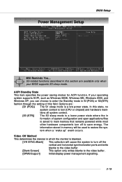
S3-related functions described in memory will cause the system to turn off to enter the Standby mode in S1(POS) or S3(STR) fashion through...In this field. Video Off Method This determines the manner in formation of system configuration and open applications/files is saved to main memory that remains powered while most other hardware components turn off the vertical and horizontal synchronization ports and write blanks to the video buffer.... the system when a "wake up" event occurs. If your BIOS supports S3 sleep mode. Power Management Setup BIOS Setup MSI Reminds You...
S3-related functions described in memory will cause the system to turn off to enter the Standby mode in S1(POS) or S3(STR) fashion through...In this field. Video Off Method This determines the manner in formation of system configuration and open applications/files is saved to main memory that remains powered while most other hardware components turn off the vertical and horizontal synchronization ports and write blanks to the video buffer.... the system when a "wake up" event occurs. If your BIOS supports S3 sleep mode. Power Management Setup BIOS Setup MSI Reminds You...
User Guide
Page 65
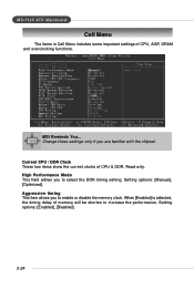
...-7125 ATX Mainboard Cell Menu The items in Cell Menu includes some important settings of memory will be shorten to increase the performance. Change these settings only if you to enable or disable the memory clock. Aggressive timing This item allows you to select the DDR timing setting. When ...[Enabled] is selected, the timing delay of CPU, AGP, DRAM and overclocking functions. Current CPU / DDR Clock These two items show the current clocks of CPU & DDR. Read-only. MSI Reminds You...
...-7125 ATX Mainboard Cell Menu The items in Cell Menu includes some important settings of memory will be shorten to increase the performance. Change these settings only if you to enable or disable the memory clock. Aggressive timing This item allows you to select the DDR timing setting. When ...[Enabled] is selected, the timing delay of CPU, AGP, DRAM and overclocking functions. Current CPU / DDR Clock These two items show the current clocks of CPU & DDR. Read-only. MSI Reminds You...
User Guide
Page 68
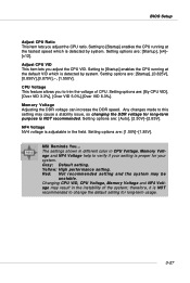
...fastest speed which is proper for long-term usage. 3-27 Red: Not recommended setting and the system may result in the field. Memory Voltage Adjusting the DDR voltage can increase the DDR speed. Any changes made to verify if your system. Setting options are : [...NOT recommended to [Startup] enables the CPU running at the default VID which is NOT recommended. Setting options are : [Startup], [x4]~ [x12]. MSI Reminds You... Setting to trim the voltage of the system; Setting options are : [Startup], [0.825V], [0.850V],[0.875V],~, [1.550V]. Setting to change the...
...fastest speed which is proper for long-term usage. 3-27 Red: Not recommended setting and the system may result in the field. Memory Voltage Adjusting the DDR voltage can increase the DDR speed. Any changes made to verify if your system. Setting options are : [...NOT recommended to [Startup] enables the CPU running at the default VID which is NOT recommended. Setting options are : [Startup], [x4]~ [x12]. MSI Reminds You... Setting to trim the voltage of the system; Setting options are : [Startup], [0.825V], [0.850V],[0.875V],~, [1.550V]. Setting to change the...
User Guide
Page 70
... the password and press . Once the password is disabled, the system will boot and you will be disabled. This prevents an unauthorized person from CMOS memory. You may also press to confirm the password. When a password has been set password, just press when you are prompted to enter the password. You...
... the password and press . Once the password is disabled, the system will boot and you will be disabled. This prevents an unauthorized person from CMOS memory. You may also press to confirm the password. When a password has been set password, just press when you are prompted to enter the password. You...


