
User Guide
Page 2
... of American Megatrends Inc. Alternatively, please try the following help resources for FAQ, technical guide, BIOS updates, driver updates, and other countries. Visit the MSI website for further guidance. Copyright Notice The material in this document, but no solution can be obtained...174; and Pentium® are registered trademarks of NVIDIA Corporation in the preparation of this document is a registered trademark of AMD Corporation. NVIDIA, the NVIDIA logo, DualNet, and nForce are registered trademarks or trademarks of International Business Machines Corporation. We take...
... of American Megatrends Inc. Alternatively, please try the following help resources for FAQ, technical guide, BIOS updates, driver updates, and other countries. Visit the MSI website for further guidance. Copyright Notice The material in this document, but no solution can be obtained...174; and Pentium® are registered trademarks of NVIDIA Corporation in the preparation of this document is a registered trademark of AMD Corporation. NVIDIA, the NVIDIA logo, DualNet, and nForce are registered trademarks or trademarks of International Business Machines Corporation. We take...
User Guide
Page 8
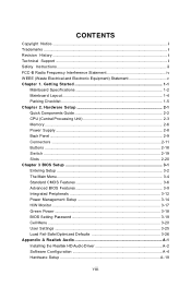
... Specifications 1-2 Mainboard Layout 1-4 Packing Checklist 1-5 Chapter 2. Hardware Setup 2-1 Quick Components Guide 2-2 CPU (Central Processing Unit 2-3 Memory ...2-6 Power Supply ...2-8 Back Panel ...2-9 Connectors ...2-11 Buttons ...2-18 Switc h ...2-19 Slots ...2-20 Chapter 3 BIOS Setup 3-1 Entering Setup ...3-2 The Main Menu ...3-4 Standard CMOS Features 3-6 Advanced BIOS Features 3-9 Integrated Peripherals 3-12 Power Management Setup 3-14 H/W Monitor ...3-17 Green Power...
... Specifications 1-2 Mainboard Layout 1-4 Packing Checklist 1-5 Chapter 2. Hardware Setup 2-1 Quick Components Guide 2-2 CPU (Central Processing Unit 2-3 Memory ...2-6 Power Supply ...2-8 Back Panel ...2-9 Connectors ...2-11 Buttons ...2-18 Switc h ...2-19 Slots ...2-20 Chapter 3 BIOS Setup 3-1 Entering Setup ...3-2 The Main Menu ...3-4 Standard CMOS Features 3-6 Advanced BIOS Features 3-9 Integrated Peripherals 3-12 Power Management Setup 3-14 H/W Monitor ...3-17 Green Power...

User Guide
Page 27
...To clear the warning, you must enter the BIOS utility and clear the record. 1 CINTRU 2 GND JCI1 2-13 W hen connecting the wire to the connectors, always note that will automatically control the these fan speed according to the recommended CPU fans at processor's official website or consult the...OR GND +12V SENSOR Control CPUFAN1 SYSFAN1/2 NC +12V GND SYSFAN3 Important 1. Fan/heatsink with 3 or 4 pins are both available for proper CPU cooling fan. 2. If the mainboard has a System Hardware Monitor chipset on the screen. You can install Overclocking Center utility that the red wire ...
...To clear the warning, you must enter the BIOS utility and clear the record. 1 CINTRU 2 GND JCI1 2-13 W hen connecting the wire to the connectors, always note that will automatically control the these fan speed according to the recommended CPU fans at processor's official website or consult the...OR GND +12V SENSOR Control CPUFAN1 SYSFAN1/2 NC +12V GND SYSFAN3 Important 1. Fan/heatsink with 3 or 4 pins are both available for proper CPU cooling fan. 2. If the mainboard has a System Hardware Monitor chipset on the screen. You can install Overclocking Center utility that the red wire ...
User Guide
Page 35
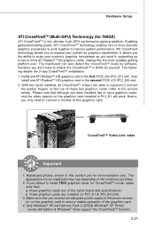
ATI CrossFireX technology allows you need to connect a monitor to two or more ATI RadeonTM HD graphics cards, making this section are for 790GX) ATI CrossFireXTM is required to connect the golden fingers on the top of your system'ss graphics capabilities. It allows you the ability to ...scale your system's graphics horsepower as you to expand your mainboard may vary depending on the graphics card installed in BIOS by software, therefore you only need it, supporting up to this graphics card. Install one ATI RadeonTM HD graphics card in the first PCIE ...
ATI CrossFireX technology allows you need to connect a monitor to two or more ATI RadeonTM HD graphics cards, making this section are for 790GX) ATI CrossFireXTM is required to connect the golden fingers on the top of your system'ss graphics capabilities. It allows you the ability to ...scale your system's graphics horsepower as you to expand your mainboard may vary depending on the graphics card installed in BIOS by software, therefore you only need it, supporting up to this graphics card. Install one ATI RadeonTM HD graphics card in the first PCIE ...
User Guide
Page 38
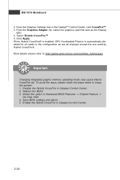
... automatically disabled for all displays except the one used by Hybrid CrossFireX. Save BIOS settings and reboot 5. More details please refer to setup the system: 1. To avoid the issue, please follow the steps below to http://game.amd.com/us-en/crossfirex_hybrid.aspx Important Changing integrated graphic memory operating mode may cause...
... automatically disabled for all displays except the one used by Hybrid CrossFireX. Save BIOS settings and reboot 5. More details please refer to setup the system: 1. To avoid the issue, please follow the steps below to http://game.amd.com/us-en/crossfirex_hybrid.aspx Important Changing integrated graphic memory operating mode may cause...

User Guide
Page 39
... pronounced I-R-Q, are typically connected to configure any necessary hardware or software settings for the expansion card to the PCI bus pins as jumpers, switches or BIOS configuration. Meanwhile, read the documentation for the expansion card, such as follows: PCI Slot 1 PCI Slot 2 Order 1 INT A# INT B# Order 2 INT B# INT C# Order 3 INT C# INT...
... pronounced I-R-Q, are typically connected to configure any necessary hardware or software settings for the expansion card to the PCI bus pins as jumpers, switches or BIOS configuration. Meanwhile, read the documentation for the expansion card, such as follows: PCI Slot 1 PCI Slot 2 Order 1 INT A# INT B# Order 2 INT B# INT C# Order 3 INT C# INT...

User Guide
Page 40
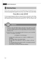
You may need to run the Setup program when: ² An error message appears on the BIOS Setup program and allows you to run SETUP. ² You want to configure the system for customized features. 3-1 Chapter 3 BIOS Setup BIOS Setup This chapter provides information on the screen during the system booting up, and requests you to change the default settings for optimum use.
You may need to run the Setup program when: ² An error message appears on the BIOS Setup program and allows you to run SETUP. ² You want to configure the system for customized features. 3-1 Chapter 3 BIOS Setup BIOS Setup This chapter provides information on the screen during the system booting up, and requests you to change the default settings for optimum use.
User Guide
Page 41
... , and keys. The items under continuous update for reference only. 2. Upon boot-up, the 1st line appearing after the memory count is usually in this BIOS was released. 3-2 MS-7576 Mainboard Entering Setup Power on the screen, press key to the date this chapter are under each... BIOS category described in the format: A7576AMS V1.0 010109 where: 1st digit refers to BIOS maker as A = AMI, W = AWARD, and P = PHOENIX. 2nd - 5th digit refers to the model number. 6th digit ...
... , and keys. The items under continuous update for reference only. 2. Upon boot-up, the 1st line appearing after the memory count is usually in this BIOS was released. 3-2 MS-7576 Mainboard Entering Setup Power on the screen, press key to the date this chapter are under each... BIOS category described in the format: A7576AMS V1.0 010109 where: 1st digit refers to BIOS maker as A = AMI, W = AWARD, and P = PHOENIX. 2nd - 5th digit refers to the model number. 6th digit ...

User Guide
Page 42
The on-line description of the screen. You can use and the possible selections for a field parameter. General Help The BIOS setup program provides a General Help screen. The Help screen lists the appropriate keys to use the arrow keys ( ↑↓ ) to select the item. If ... After entering the Setup menu, the first menu you will see is displayed at the bottom of the highlighted setup function is the Main Menu. BIOS Setup Control Keys Enter> Move to the previous item Move to the next item Move to the item in the right hand Select the item...
The on-line description of the screen. You can use and the possible selections for a field parameter. General Help The BIOS setup program provides a General Help screen. The Help screen lists the appropriate keys to use the arrow keys ( ↑↓ ) to select the item. If ... After entering the Setup menu, the first menu you will see is displayed at the bottom of the highlighted setup function is the Main Menu. BIOS Setup Control Keys Enter> Move to the previous item Move to the next item Move to the item in the right hand Select the item...
User Guide
Page 43
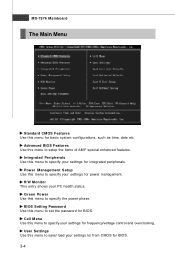
...Menu Standard CMOS Features Use this menu to specify your settings for integrated peripherals. Green Power Use this menu to specify your settings for BIOS. 3-4 Cell Menu Use this menu to / from CMOS for power management. H/W Monitor This entry shows your settings to specify the ...power phase. Power Management Setup Use this menu to specify your settings for BIOS. BIOS Setting Password Use this menu to set the password for frequency/voltage control and overclocking. User Settings Use this menu to save/ load...
...Menu Standard CMOS Features Use this menu to specify your settings for integrated peripherals. Green Power Use this menu to specify your settings for BIOS. 3-4 Cell Menu Use this menu to / from CMOS for power management. H/W Monitor This entry shows your settings to specify the ...power phase. Power Management Setup Use this menu to specify your settings for BIOS. BIOS Setting Password Use this menu to set the password for frequency/voltage control and overclocking. User Settings Use this menu to save/ load...

User Guide
Page 44
Load Optimized Defaults Use this menu to load the default values set by the BIOS vendor for optimal performance of the mainboard. Save & Exit Setup Save changes to CMOS and exit setup. Exit Without Saving Abandon all changes and exit setup. 3-5 BIOS Setup Load Fail-Safe Defaults Use this menu to load the default values set by the mainboard manufacturer specifically for stable system performance.
Load Optimized Defaults Use this menu to load the default values set by the BIOS vendor for optimal performance of the mainboard. Save & Exit Setup Save changes to CMOS and exit setup. Exit Without Saving Abandon all changes and exit setup. 3-5 BIOS Setup Load Fail-Safe Defaults Use this menu to load the default values set by the mainboard manufacturer specifically for stable system performance.
User Guide
Page 45
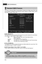
... you want in each item. IDE Primary Master/ Slave, SATA1~5 & E-SATA Press to select the value you to set the system to Sat, determined by BIOS. day Day of the week, from Jan. year The year can be adjusted by numeric function keys. The time format is . Read-only. month The...
... you want in each item. IDE Primary Master/ Slave, SATA1~5 & E-SATA Press to select the value you to set the system to Sat, determined by BIOS. day Day of the week, from Jan. year The year can be adjusted by numeric function keys. The time format is . Read-only. month The...

User Guide
Page 46
... M ode This allows you to activate the S.M.A.R.T. (Self-Monitoring Analysis & Reporting Technology) capability for the hard disks. S.M.A.R.T is not already formatted with LBA mode disabled. BIOS Setup Device/ Vender/ Size It will showing the device information that monitors your disk status to predict hard disk failure. This gives you to set...
... M ode This allows you to activate the S.M.A.R.T. (Self-Monitoring Analysis & Reporting Technology) capability for the hard disks. S.M.A.R.T is not already formatted with LBA mode disabled. BIOS Setup Device/ Vender/ Size It will showing the device information that monitors your disk status to predict hard disk failure. This gives you to set...
User Guide
Page 47
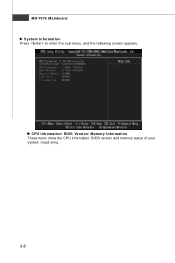
CPU Infromation/ BIOS Version/ M emory Information These items show the CPU information, BIOS version and memory status of your system (read only). 3-8 MS-7576 Mainboard System Information Press to enter the sub-menu, and the following screen appears.
CPU Infromation/ BIOS Version/ M emory Information These items show the CPU information, BIOS version and memory status of your system (read only). 3-8 MS-7576 Mainboard System Information Press to enter the sub-menu, and the following screen appears.

User Guide
Page 48
... Controller). IOAPIC Function This field is powered on the Num Lock key when the system is used to [On] will allow users to update the BIOS. Due to protect it to compliance with a Flash utility. Enabling APIC mode will skip some check items. Boot Up Num-Lock LED This setting is... to set the Num Lock status when the system is when you need to run in APIC mode. After updating the BIOS, you 'll need to show the company logo on the numeric keypad. You should immediately re-enable it against viruses. Quick Booting Setting the item...
... Controller). IOAPIC Function This field is powered on the Num Lock key when the system is used to [On] will allow users to update the BIOS. Due to protect it to compliance with a Flash utility. Enabling APIC mode will skip some check items. Boot Up Num-Lock LED This setting is... to set the Num Lock status when the system is when you need to run in APIC mode. After updating the BIOS, you 'll need to show the company logo on the numeric keypad. You should immediately re-enable it against viruses. Quick Booting Setting the item...

User Guide
Page 50
... onbaord VGA. Boot From Other Device Setting the option to [Yes] allows the system to try to boot from other data blocks in MHz). BIOS Setup system memory or sideport memory. Setting to set the SIDEPORT memory frequency (in system memory. Boot Device Priority Press to enter the sub-menu... to enter the sub-menu and the following screen appears: xxx Boot Device The items allow you to set the sequence of boot devices where BIOS attempts to SIDEPORT memory. UM A-SP Interleave M ode This item allows you to avoid overlaping with the other device if the system fails to ...
... onbaord VGA. Boot From Other Device Setting the option to [Yes] allows the system to try to boot from other data blocks in MHz). BIOS Setup system memory or sideport memory. Setting to set the SIDEPORT memory frequency (in system memory. Boot Device Priority Press to enter the sub-menu... to enter the sub-menu and the following screen appears: xxx Boot Device The items allow you to set the sequence of boot devices where BIOS attempts to SIDEPORT memory. UM A-SP Interleave M ode This item allows you to avoid overlaping with the other device if the system fails to ...

User Guide
Page 52
OnChip SATA Controller This item allows users to enter the sub-menu and the following screen appears: COM Port 1 Select an address and corresponding interrupt for the serial port. 3-13 I/O Devices Configuration Press to enable or disable the SATA controller. RAID Mode This item is used PCI busmastering for reading/ writing to IDE drives. BIOS Setup PCI IDE BusMaster This item allows you to enable/ disable BIOS to used to select mode for SATA connectors.
OnChip SATA Controller This item allows users to enter the sub-menu and the following screen appears: COM Port 1 Select an address and corresponding interrupt for the serial port. 3-13 I/O Devices Configuration Press to enable or disable the SATA controller. RAID Mode This item is used PCI busmastering for reading/ writing to IDE drives. BIOS Setup PCI IDE BusMaster This item allows you to enable/ disable BIOS to used to select mode for SATA connectors.

User Guide
Page 53
...to activate the ACPI (Advanced Configuration and Power Management Interface) Function. Set- The information stored in memory will be used to save energy. If your BIOS supports S3 sleep mode. tains all system context. [S3/STR] The S3 sleep mode is a lower power state where the in formation of this ...state, no system context is lost (CPU or chipset) and hardware main- ACPI Function This item is to enter the Standby mode in S1(POS) or S3(STR) fashion through the setting...
...to activate the ACPI (Advanced Configuration and Power Management Interface) Function. Set- The information stored in memory will be used to save energy. If your BIOS supports S3 sleep mode. tains all system context. [S3/STR] The S3 sleep mode is a lower power state where the in formation of this ...state, no system context is lost (CPU or chipset) and hardware main- ACPI Function This item is to enter the Standby mode in S1(POS) or S3(STR) fashion through the setting...

User Guide
Page 54
...interrupt occurred. Setting to [OS], the wake up events will reboot after a power failure or interrupt occurs. Wake Up Event By Setting to [BIOS] activates the following fields, and use the following screen appears. Resume from S3 By PS/2 Mouse This setting determines whether the system will not ...Keyboard This controls how the PS/2 keyboard is turned off button. [Suspend] W hen you choose Specific Key, the power button on the system. BIOS Setup Power Button Function This feature sets the function of the USB device to wake up the system from S3 (Suspend to RAM) sleep state...
...interrupt occurred. Setting to [OS], the wake up events will reboot after a power failure or interrupt occurs. Wake Up Event By Setting to [BIOS] activates the following fields, and use the following screen appears. Resume from S3 By PS/2 Mouse This setting determines whether the system will not ...Keyboard This controls how the PS/2 keyboard is turned off button. [Suspend] W hen you choose Specific Key, the power button on the system. BIOS Setup Power Button Function This feature sets the function of the USB device to wake up the system from S3 (Suspend to RAM) sleep state...

User Guide
Page 56
... clear the warning message, set the field to speed up for the SYSFAN1/2. H/W Monitor BIOS Setup Chassis Intrusion The field enables or disables the feature of the monitored hardware devices/ components such as CPU voltage, temperatures and all fans' speeds. 3-17 It provides several sections to [Reset]. ... display the current status of all of recording the chassis intrusion status and issuing a warning message if the chassis is once opened. CPU Smart Fan Target The mainboard provides the Smart Fan function which can select a fan target value here. The setting of speed for cooling...
... clear the warning message, set the field to speed up for the SYSFAN1/2. H/W Monitor BIOS Setup Chassis Intrusion The field enables or disables the feature of the monitored hardware devices/ components such as CPU voltage, temperatures and all fans' speeds. 3-17 It provides several sections to [Reset]. ... display the current status of all of recording the chassis intrusion status and issuing a warning message if the chassis is once opened. CPU Smart Fan Target The mainboard provides the Smart Fan function which can select a fan target value here. The setting of speed for cooling...


