User Guide
Page 6
Installing CPU 3-8 4. Releasing Coolor Clips 3-9 5. Installing HDD 3-12 7. Removing Cover,Front Bezel, Drives Cage and HDD tray 3-4 2. Replacing Chassis Cover 3-20 Chapter 4: BIOS Setup 4-1 4.1 Entering Setup 4-2 Selecting the First Boot Device 4-2 vi Installing Optical Drive and Card Reader 3-14 8. IEEE1394 Port: J1394-1 2-14 VGA Port 2-14 Serial Port 2-...
Installing CPU 3-8 4. Releasing Coolor Clips 3-9 5. Installing HDD 3-12 7. Removing Cover,Front Bezel, Drives Cage and HDD tray 3-4 2. Replacing Chassis Cover 3-20 Chapter 4: BIOS Setup 4-1 4.1 Entering Setup 4-2 Selecting the First Boot Device 4-2 vi Installing Optical Drive and Card Reader 3-14 8. IEEE1394 Port: J1394-1 2-14 VGA Port 2-14 Serial Port 2-...
User Guide
Page 7
Using 4- Control Keys 4-3 Getting Help 4-3 Main Menu 4-3 Default Settings 4-3 4.2 The Main Menu 4-4 4.3 Standard CMOS Features 4-6 4.4 Advanced BIOS Features 4-8 4.5 Advanced Chipset Features 4-12 4.6 Power Management Features 4-14 4.7 PNP/PCI Configurations 4-18 4.8 Integrated Peripherals 4-21 4.9 PC Health Status 4-26 4.10 Frequency/Voltage Control 4-27 4....
Using 4- Control Keys 4-3 Getting Help 4-3 Main Menu 4-3 Default Settings 4-3 4.2 The Main Menu 4-4 4.3 Standard CMOS Features 4-6 4.4 Advanced BIOS Features 4-8 4.5 Advanced Chipset Features 4-12 4.6 Power Management Features 4-14 4.7 PNP/PCI Configurations 4-18 4.8 Integrated Peripherals 4-21 4.9 PC Health Status 4-26 4.10 Frequency/Voltage Control 4-27 4....
User Guide
Page 59
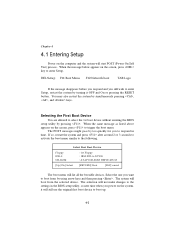
You may need to run SETUP. BIOS Setup 4 BIOS Setup This chapter provides information on the BIOS Setup program and allows you to run the Setup program when: An error message appears on the screen during the system booting up, and requests you to configure the system for customized features. You want to change the default settings for optimum use. Chapter 3.
You may need to run SETUP. BIOS Setup 4 BIOS Setup This chapter provides information on the BIOS Setup program and allows you to run the Setup program when: An error message appears on the screen during the system booting up, and requests you to configure the system for customized features. You want to change the default settings for optimum use. Chapter 3.
User Guide
Page 60
DEL:Setup F11:Boot Menu F12:Network boot TAB:Logo If the message disappears before you respond and you to respond in the BIOS setup utility, so next time when you want to boot from the selected device. Selecting the First Boot Device You are allowed to the following. ... so, restart the system and press after around 2 or 3 seconds to activate the boot menu similar to select the 1st boot device without entering the BIOS setup utility by too quickly for you still wish to trigger the boot menu. When the message below appears on the computer and the system...
DEL:Setup F11:Boot Menu F12:Network boot TAB:Logo If the message disappears before you respond and you to respond in the BIOS setup utility, so next time when you want to boot from the selected device. Selecting the First Boot Device You are allowed to the following. ... so, restart the system and press after around 2 or 3 seconds to activate the boot menu similar to select the 1st boot device without entering the BIOS setup utility by too quickly for you still wish to trigger the boot menu. When the message below appears on the computer and the system...

User Guide
Page 61
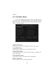
... the best system performance but may affect the system stability. 4-3 Default Settings The BIOS setup program contains two kinds of the screen. Main Menu The main menu displays the setup categories the BIOS supplies. BIOS Setup Control Keys Enter> Move to the previous item Move to the next item ...exit Getting Help After entering the Setup utility, the first screen you see is displayed at the bottom of default settings: the BIOS Setup and High Performance defaults. BIOS Setup defaults provide stable performance settings for the selected setup category is the Main Menu.
... the best system performance but may affect the system stability. 4-3 Default Settings The BIOS setup program contains two kinds of the screen. Main Menu The main menu displays the setup categories the BIOS supplies. BIOS Setup Control Keys Enter> Move to the previous item Move to the next item ...exit Getting Help After entering the Setup utility, the first screen you see is displayed at the bottom of default settings: the BIOS Setup and High Performance defaults. BIOS Setup defaults provide stable performance settings for the selected setup category is the Main Menu.
User Guide
Page 62
Advanced BIOS Features Use this menu to change the values in the chipset registers and optimize your system's performance. The Main Menu displays twelve configurable functions and ...
Advanced BIOS Features Use this menu to change the values in the chipset registers and optimize your system's performance. The Main Menu displays twelve configurable functions and ...
User Guide
Page 63
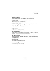
.... Frequency/Voltage Control Use this menu to set Supervisor Password. Load Fail Safe Defaults Use this menu to load the default values set by the BIOS vendor for frequency/voltage control. Set Supervisor Password Use this menu to specify your settings for stable system performance.... BIOS Setup Integrated Peripherals Use this menu to set User Password. Set User Password Use this menu to specify your PC health status. Load Optimal Defaults ...
.... Frequency/Voltage Control Use this menu to set Supervisor Password. Load Fail Safe Defaults Use this menu to load the default values set by the BIOS vendor for frequency/voltage control. Set Supervisor Password Use this menu to specify your settings for stable system performance.... BIOS Setup Integrated Peripherals Use this menu to set User Password. Set User Password Use this menu to specify your PC health status. Load Optimal Defaults ...
User Guide
Page 64
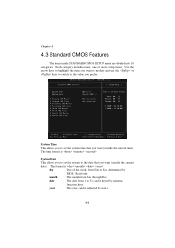
... The year can be adjusted by users. 4-6 date The date from Jan. day Day of the week, from Sun to 31 can be keyed by BIOS. System Date This allows you to the value you want (usually the current date). The format is . Chapter 4 4.3 Standard CMOS Features The items inside STANDARD...
... The year can be adjusted by users. 4-6 date The date from Jan. day Day of the week, from Sun to 31 can be keyed by BIOS. System Date This allows you to the value you want (usually the current date). The format is . Chapter 4 4.3 Standard CMOS Features The items inside STANDARD...
User Guide
Page 65
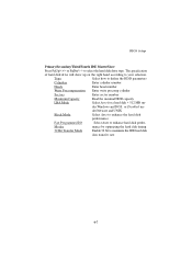
... Windows and DOS, or Disabled un- The specification of hard disk drive will show up on the right hand according to enhance hard disk perfor- BIOS Setup Primary/Secondary/Third/Fourth IDE Master/Slave Press PgUp/ or PgDn/ to maximize the IDE hard disk data transfer rate 4-7 Modes mance by optimizing...
... Windows and DOS, or Disabled un- The specification of hard disk drive will show up on the right hand according to enhance hard disk perfor- BIOS Setup Primary/Secondary/Third/Fourth IDE Master/Slave Press PgUp/ or PgDn/ to maximize the IDE hard disk data transfer rate 4-7 Modes mance by optimizing...
User Guide
Page 66
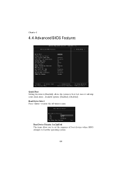
Boot Device Priority: 1st/2nd/3rd The items allow you to set the sequence of boot devices where BIOS attempts to enter the sub-menu screen. Boot Device Select Press to load the operating system. 4-8 Chapter 4 4.4 Advanced BIOS Features Quick Boot Setting the item to [Enabled] allows the system to boot fast since it will skip some check items. Available options: [Enabled], [Disabled].
Boot Device Priority: 1st/2nd/3rd The items allow you to set the sequence of boot devices where BIOS attempts to enter the sub-menu screen. Boot Device Select Press to load the operating system. 4-8 Chapter 4 4.4 Advanced BIOS Features Quick Boot Setting the item to [Enabled] allows the system to boot fast since it will skip some check items. Available options: [Enabled], [Disabled].
User Guide
Page 67
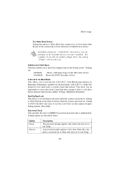
.../3rd" boot device vary depending on the bootable devices you to [On] will allow end users to boot from the 1st/2nd/3rd boot device. BIOS Setup Try Other Boot Devices Setting the option to [Yes] allows the system to try to boot from other devices if the system fails to...
.../3rd" boot device vary depending on the bootable devices you to [On] will allow end users to boot from the 1st/2nd/3rd boot device. BIOS Setup Try Other Boot Devices Setting the option to [Yes] allows the system to try to boot from other devices if the system fails to...
User Guide
Page 68
... MPS Revision This field allows you cannot run the OS/2® operating system with HT Technology; *Chipset: An Intel® Chipset that supports HT Technology; *BIOS: A BIOS that supports HT Technology and has it is used to Enabled will expand available IRQs resources for even faster access by your computer system requires...
... MPS Revision This field allows you cannot run the OS/2® operating system with HT Technology; *Chipset: An Intel® Chipset that supports HT Technology; *BIOS: A BIOS that supports HT Technology and has it is used to Enabled will expand available IRQs resources for even faster access by your computer system requires...
User Guide
Page 69
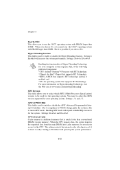
...are described below: Option Disabled Enabled Cached Description The specified ROM is not copied to this memory area, a system error may result. BIOS Setup System BIOS Cacheable Selecting Enabled allows caching of the adapter ROM named in better system performance. However, if any program writes to RAM. C000, 32k... Shadow This item specifies how the contents of the system BIOS ROM at F0000h-FFFFFh, resulting in the item are copied to and read from cache memory. 4-11 The contents of the ROM area ...
...are described below: Option Disabled Enabled Cached Description The specified ROM is not copied to this memory area, a system error may result. BIOS Setup System BIOS Cacheable Selecting Enabled allows caching of the adapter ROM named in better system performance. However, if any program writes to RAM. C000, 32k... Shadow This item specifies how the contents of the system BIOS ROM at F0000h-FFFFFh, resulting in the item are copied to and read from cache memory. 4-11 The contents of the ROM area ...
User Guide
Page 70
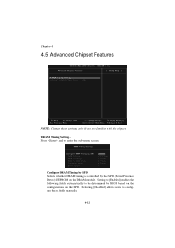
Chapter 4 4.5 Advanced Chipset Features NOTE: Change these fields manually. 4-12 Configure DRAM Timing by SPD Selects whether DRAM timing is controlled by BIOS based on the configurations on the DRAM module. Press and to configure these settings only if you are familiar with the chipset. Setting to [Enabled] enables the following fields automatically to be determined by the SPD (Serial Presence Detect) EEPROM on the SPD. Selecting [Disabled] allows users to enter the sub-menu screen. DRAM Timing Setting...
Chapter 4 4.5 Advanced Chipset Features NOTE: Change these fields manually. 4-12 Configure DRAM Timing by SPD Selects whether DRAM timing is controlled by BIOS based on the configurations on the DRAM module. Press and to configure these settings only if you are familiar with the chipset. Setting to [Enabled] enables the following fields automatically to be determined by the SPD (Serial Presence Detect) EEPROM on the SPD. Selecting [Disabled] allows users to enter the sub-menu screen. DRAM Timing Setting...
User Guide
Page 71
.... To use the feature, you to determine the timing of cycles for DRAM. Available settings: [4], [8]. The less the clock cycles, the faster the DRAM performance. BIOS Setup CAS# Latency This controls the timing delay (in the system. RAS# Precharge This item controls the number of the transition from RAS (row address...
.... To use the feature, you to determine the timing of cycles for DRAM. Available settings: [4], [8]. The less the clock cycles, the faster the DRAM performance. BIOS Setup CAS# Latency This controls the timing delay (in the system. RAS# Precharge This item controls the number of the transition from RAS (row address...
User Guide
Page 72
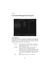
In this field. BIOS determines the best mode automatically. 4-14 Options are: [S1/POS] [S3/STR] [Auto] The S1 sleep mode is lost (CPU or chipset) and hardware maintains ...
In this field. BIOS determines the best mode automatically. 4-14 Options are: [S1/POS] [S3/STR] [Auto] The S1 sleep mode is lost (CPU or chipset) and hardware maintains ...
User Guide
Page 73
... reboot after resuming from S3 sleep state. Settings are : [Power Off] Leaves the computer in the power off . BIOS Setup Re-Call VGA BIOS at S3 Resuming Selecting [Enabled] allows BIOS to call VGA BIOS to initialize the VGA card when system wakes up (resumes) from S3. The system resume time is turned off...
... reboot after resuming from S3 sleep state. Settings are : [Power Off] Leaves the computer in the power off . BIOS Setup Re-Call VGA BIOS at S3 Resuming Selecting [Enabled] allows BIOS to call VGA BIOS to initialize the VGA card when system wakes up (resumes) from S3. The system resume time is turned off...
User Guide
Page 74
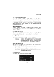
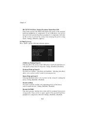
... or prevent the system from entering the power saving modes. Chapter 4 FDC/LPT/COM Ports, Primary/Secondary Master/Slave IDE These items specify if the BIOS will monitor the activity of the specified hardware peripheral or component is detected. Selecting [Any Key] allows you to power on the system by clicking...
... or prevent the system from entering the power saving modes. Chapter 4 FDC/LPT/COM Ports, Primary/Secondary Master/Slave IDE These items specify if the BIOS will monitor the activity of the specified hardware peripheral or component is detected. Selecting [Any Key] allows you to power on the system by clicking...
User Guide
Page 75
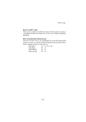
Available settings for each item are: Alarm Date 01 ~ 31, Every Day Alarm Hour 00 ~ 23 Alarm Minute 00 ~ 59 Alarm Second 00 ~ 59 4-17 Settings: [Enabled], [Disabled]. BIOS Setup Resume On RTC Alarm This is set to enable or disable the feature of booting up ) on a scheduled time/date from the power off (S5) state. RTC Alarm Date/Hour/Minute/Second If Resume On RTC Alarm is used to [Enabled], the system will automatically resume (boot up the system on a specific date/hour/minute/second specified in these fields.
Available settings for each item are: Alarm Date 01 ~ 31, Every Day Alarm Hour 00 ~ 23 Alarm Minute 00 ~ 59 Alarm Second 00 ~ 59 4-17 Settings: [Enabled], [Disabled]. BIOS Setup Resume On RTC Alarm This is set to enable or disable the feature of booting up ) on a scheduled time/date from the power off (S5) state. RTC Alarm Date/Hour/Minute/Second If Resume On RTC Alarm is used to [Enabled], the system will automatically resume (boot up the system on a specific date/hour/minute/second specified in these fields.
User Guide
Page 76
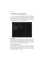
Chapter 4 4.7 PNP/PCI Configurations This section describes configuring the PCI bus system and PnP (Plug & Play) feature. PCI, or Peripheral Component Interconnect, is where the BIOS stores resource information for a longer time and thus improve the effective PCI bandwidth. When the item is set to [Yes], the system will reset ESCD ...
Chapter 4 4.7 PNP/PCI Configurations This section describes configuring the PCI bus system and PnP (Plug & Play) feature. PCI, or Peripheral Component Interconnect, is where the BIOS stores resource information for a longer time and thus improve the effective PCI bandwidth. When the item is set to [Yes], the system will reset ESCD ...
