
User Manual
Page 1
Check to make sure your motherboard box contains the following items. If something is missing, contact your dealer as soon as possible. Motherboard Drivers & Utilities Disc I/O Shield Case Badge SATA Cable x2 M.2 Screw x1 Unpacking 1 Unpacking Thank you for buying the MSI® B360-A PRO motherboard.
Check to make sure your motherboard box contains the following items. If something is missing, contact your dealer as soon as possible. Motherboard Drivers & Utilities Disc I/O Shield Case Badge SATA Cable x2 M.2 Screw x1 Unpacking 1 Unpacking Thank you for buying the MSI® B360-A PRO motherboard.

User Manual
Page 2
... could cause permanent damage to ensure successful computer assembly. y Keep this user guide for future reference. Loose connections may damage the motherboard. 2 Safety Information If an ESD wrist strap is not available, discharge yourself of breakage. y Before turning on the computer, ...ensure that all components are no loose screws or metal components on the motherboard or anywhere within the computer case. y If any installation step, please consult a certified computer technician. y Do not leave this...
... could cause permanent damage to ensure successful computer assembly. y Keep this user guide for future reference. Loose connections may damage the motherboard. 2 Safety Information If an ESD wrist strap is not available, discharge yourself of breakage. y Before turning on the computer, ...ensure that all components are no loose screws or metal components on the motherboard or anywhere within the computer case. y If any installation step, please consult a certified computer technician. y Do not leave this...

User Manual
Page 7
Installing the Motherboard 1 2 Quick Start 7 BAT1
Installing the Motherboard 1 2 Quick Start 7 BAT1

User Manual
Page 13
Contents Unpacking ...1 Safety Information 2 Quick Start ...3 Preparing Tools and Components 3 Installing a Processor 4 Installing DDR4 memory 5 Connecting the Front Panel Header 6 Installing the Motherboard 7 Installing SATA Drives 8 Installing a Graphics Card 9 Connecting Peripheral Devices 10 Connecting the Power Connectors 11 Power On...12 Specifications...15 Block Diagram ...19 Rear I/O Panel ......
Contents Unpacking ...1 Safety Information 2 Quick Start ...3 Preparing Tools and Components 3 Installing a Processor 4 Installing DDR4 memory 5 Connecting the Front Panel Header 6 Installing the Motherboard 7 Installing SATA Drives 8 Installing a Graphics Card 9 Connecting Peripheral Devices 10 Connecting the Power Connectors 11 Power On...12 Specifications...15 Block Diagram ...19 Rear I/O Panel ......

User Manual
Page 25
...heatsink to assist in the heatsink/ cooler package for motherboard placement. CPU Socket Distance from the power outlet before booting your system. MSI will deal with Return Merchandise Authorization (RMA) requests if only the motherboard comes with the CPU before installing or removing the CPU.... y Confirm that all other system components can seriously damage the CPU and motherboard. y If you purchased ...
...heatsink to assist in the heatsink/ cooler package for motherboard placement. CPU Socket Distance from the power outlet before booting your system. MSI will deal with Return Merchandise Authorization (RMA) requests if only the motherboard comes with the CPU before installing or removing the CPU.... y Confirm that all other system components can seriously damage the CPU and motherboard. y If you purchased ...

User Manual
Page 26
... install more efficient memory cooling system for 32-bit Windows OS due to protect the CPU. Go to the memory frequency operates dependent on the motherboard. y The stability and compatibility of installed memory module depend on Intel CPU specification, the Memory DIMM voltage below 1.35V is recommended to use a more than...
... install more efficient memory cooling system for 32-bit Windows OS due to protect the CPU. Go to the memory frequency operates dependent on the motherboard. y The stability and compatibility of installed memory module depend on Intel CPU specification, the Memory DIMM voltage below 1.35V is recommended to use a more than...

User Manual
Page 28
...; RST only supports PCIe M.2 SSD with the supplied M.2 screw. y Intel® OptaneTM Memory Ready. Insert your M.2 SSD. 3. Installing M.2 SSD 1. Loosen the M.2 riser screw from the motherboard. 2. Secure the M.2 SSD in place with UEFI ROM. Supplied M.2 screw 3 4 2 30° 1 28 Overview of Components Move and fasten the M.2 riser screw to Install M.2 module...
...; RST only supports PCIe M.2 SSD with the supplied M.2 screw. y Intel® OptaneTM Memory Ready. Insert your M.2 SSD. 3. Installing M.2 SSD 1. Loosen the M.2 riser screw from the motherboard. 2. Secure the M.2 SSD in place with UEFI ROM. Supplied M.2 screw 3 4 2 30° 1 28 Overview of Components Move and fasten the M.2 riser screw to Install M.2 module...

User Manual
Page 29
... SATA5 SATA4 Important y SATA1 port will be connected to one SATA device. Data loss may result during transmission otherwise. Each connector can connect to the motherboard for space saving purposes. y SATA cables have identical plugs on either sides of Components 29
... SATA5 SATA4 Important y SATA1 port will be connected to one SATA device. Data loss may result during transmission otherwise. Each connector can connect to the motherboard for space saving purposes. y SATA cables have identical plugs on either sides of Components 29

User Manual
Page 30
... 4 Ground 5 Ground 6 Ground Important Make sure that all the power cables are securely connected to a proper ATX power supply to ensure stable operation of the motherboard. 30 Overview of Components
... 4 Ground 5 Ground 6 Ground Important Make sure that all the power cables are securely connected to a proper ATX power supply to ensure stable operation of the motherboard. 30 Overview of Components

User Manual
Page 32
The Charger Port is hardware controlled by motherboard chip, it can increase USB power output for fast charging your smartphone... Watch the video to learn how to recharge your iPad,iPhone and iPod through USB ports, please install MSI® SUPER CHARGER utility. 32 Overview of Components JUSB1~2: USB 2.0 Connectors These connectors allow you will be...be/FCyvjr5NbOw Important When the Charging mode is enabled, the Charger Port data syncing will need to install the MSI® SUPER CHARGER application to avoid possible damage. Charger Port The JUSB4 connector is a charger port which ...
The Charger Port is hardware controlled by motherboard chip, it can increase USB power output for fast charging your smartphone... Watch the video to learn how to recharge your iPad,iPhone and iPod through USB ports, please install MSI® SUPER CHARGER utility. 32 Overview of Components JUSB1~2: USB 2.0 Connectors These connectors allow you will be...be/FCyvjr5NbOw Important When the Charging mode is enabled, the Charger Port data syncing will need to install the MSI® SUPER CHARGER application to avoid possible damage. Charger Port The JUSB4 connector is a charger port which ...
User Manual
Page 37
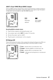
... computer. Keep Data (default) Clear CMOS/ Reset BIOS Resetting BIOS to short JBAT1 for about 5-10 seconds. 3. Plug the power cord and power on the motherboard to clear the CMOS memory. VGA - BOOT - JBAT1: Clear CMOS (Reset BIOS) Jumper There is CMOS memory onboard that is external powered from JBAT1. 4. If...
... computer. Keep Data (default) Clear CMOS/ Reset BIOS Resetting BIOS to short JBAT1 for about 5-10 seconds. 3. Plug the power cord and power on the motherboard to clear the CMOS memory. VGA - BOOT - JBAT1: Clear CMOS (Reset BIOS) Jumper There is CMOS memory onboard that is external powered from JBAT1. 4. If...
User Manual
Page 39
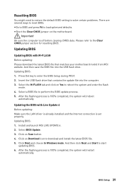
Please refer to perform the BIOS update process. 5. After the flashing process is set properly. Click on the motherboard. Insert the USB flash drive that matches your motherboard model from MSI website. Select a BIOS file to the Clear CMOS jumper section for resetting BIOS. Updating the BIOS with M-FLASH Before updating: Please download the... press F6 to enter the BIOS Setup during POST. 2. Select the M-FLASH tab and click on Download icon to start updating BIOS. 6. Install and launch MSI LIVE UPDATE 6. 2.
Please refer to perform the BIOS update process. 5. After the flashing process is set properly. Click on the motherboard. Insert the USB flash drive that matches your motherboard model from MSI website. Select a BIOS file to the Clear CMOS jumper section for resetting BIOS. Updating the BIOS with M-FLASH Before updating: Please download the... press F6 to enter the BIOS Setup during POST. 2. Select the M-FLASH tab and click on Download icon to start updating BIOS. 6. Install and launch MSI LIVE UPDATE 6. 2.

User Manual
Page 42
...; SETTINGS - please refer to be configured. 42 BIOS Setup allows you to set the speeds of fans and monitor voltages of installed devices on this motherboard. provides the way to adjust the frequency and voltage. allows you to specify the parameters for chipset and boot devices. ƒ OC - allows you to...
...; SETTINGS - please refer to be configured. 42 BIOS Setup allows you to set the speeds of fans and monitor voltages of installed devices on this motherboard. provides the way to adjust the frequency and voltage. allows you to specify the parameters for chipset and boot devices. ƒ OC - allows you to...

User Manual
Page 43
.... Advanced f PCI Subsystem Settings Sets PCI, PCI express interface protocol and latency timer. Read-only. f SATA PortX/ M2_X Shows the information of the device and motherboard.
.... Advanced f PCI Subsystem Settings Sets PCI, PCI express interface protocol and latency timer. Read-only. f SATA PortX/ M2_X Shows the information of the device and motherboard.
User Manual
Page 59
... will reboot automatically. After the flashing process is 100% completed, the system will appear after rebooting. 4. Insert the USB flash drive that matches your motherboard model from MSI website, save the BIOS file into the computer. 2. Please down-load the latest BIOS file that contains the update file into your USB flash...
... will reboot automatically. After the flashing process is 100% completed, the system will appear after rebooting. 4. Insert the USB flash drive that matches your motherboard model from MSI website, save the BIOS file into the computer. 2. Please down-load the latest BIOS file that contains the update file into your USB flash...

User Manual
Page 64
... icon and the update information will be supported by this tab to install it is a handy management application for integration of MSI applications and software interface. APP list Total Install/ Update Motherboard Information y APP list - shows the model name of all the applications and software be uninstalled simultaneously. 64 Software Description Important...
... icon and the update information will be supported by this tab to install it is a handy management application for integration of MSI applications and software interface. APP list Total Install/ Update Motherboard Information y APP list - shows the model name of all the applications and software be uninstalled simultaneously. 64 Software Description Important...

User Manual
Page 65
... appropriate drivers automatically. LIVE UPDATE 6 will see the Live update tab at the top. When you launch LIVE UPDATE 6, you to know the models of motherboard and graphics cards. y Online Help - You can also read the relevant information by clicking the information icon on websites, and don't need to update. Please...
... appropriate drivers automatically. LIVE UPDATE 6 will see the Live update tab at the top. When you launch LIVE UPDATE 6, you to know the models of motherboard and graphics cards. y Online Help - You can also read the relevant information by clicking the information icon on websites, and don't need to update. Please...

User Manual
Page 69
... filter record charts, select the check box next to the items. ƒ When click the Play button, the chart pane will start to monitor your motherboard temperature and fan speed with date and time. ƒ To make a history record: Select items and click the Record button. y Record - y Sensor...
... filter record charts, select the check box next to the items. ƒ When click the Play button, the chart pane will start to monitor your motherboard temperature and fan speed with date and time. ƒ To make a history record: Select items and click the Record button. y Record - y Sensor...

User Manual
Page 70
... arrow icon on your mobile device and connect to verify that monitoring and OC functions are working properly. Click the Spanner icon on the MSI® COMMAND CENTER APP to SoftAP with the built-in WiFi module. Select the check box next to monitor the system status. Click... the IP address on the SoftAP Management Setting area, and enter the IP address on your system. 8. Information When click the Information button, The Motherboard, CPU, Memory and HW monitor icons will slide out. 2. Gadget Mode COMMAND CENTER provides a gadget mode to the items. 3. Download and install...
... arrow icon on your mobile device and connect to verify that monitoring and OC functions are working properly. Click the Spanner icon on the MSI® COMMAND CENTER APP to SoftAP with the built-in WiFi module. Select the check box next to monitor the system status. Click... the IP address on the SoftAP Management Setting area, and enter the IP address on your system. 8. Information When click the Information button, The Motherboard, CPU, Memory and HW monitor icons will slide out. 2. Gadget Mode COMMAND CENTER provides a gadget mode to the items. 3. Download and install...

User Manual
Page 76
... possible. shows version information. If your ping for online games. y Applications - y Information - It can keep your internet fast during heavy upload/ download and improve your motherboard has a Wi-Fi module, NETWORK MANAGER provides virtual access point function for traffic shaping for the Windows 10. displays currently using network bandwidth applications. y Performance...
... possible. shows version information. If your ping for online games. y Applications - y Information - It can keep your internet fast during heavy upload/ download and improve your motherboard has a Wi-Fi module, NETWORK MANAGER provides virtual access point function for traffic shaping for the Windows 10. displays currently using network bandwidth applications. y Performance...


