
User Manual
Page 13
... 36 JRGB1: RGB LED connector 37 EZ Debug LEDs ...37 BIOS Setup ...38 Entering BIOS Setup 38 Resetting BIOS...39 Updating BIOS...39 EZ Mode ...41 Advanced Mode ...43 SETTINGS...44 Advanced...44 Boot...49 Security ...50 Save & Exit...51 OC...53 M-FLASH ...57 OC PROFILE ...58 ... 6...62 COMMAND CENTER 64 X-BOOST ...68 MYSTIC LIGHT...70 MYSTIC LIGHT PARTY 74 SMART TOOL...78 RAMDISK...80 RAID Configuration 81 Using AMD RAID Controller BIOS Configuration Utility 81 Initialize Disks ...83 Create Arrays...84 Delete Arrays ...85 Swap Arrays...86 Manage Spares ...87 Contents 13
... 36 JRGB1: RGB LED connector 37 EZ Debug LEDs ...37 BIOS Setup ...38 Entering BIOS Setup 38 Resetting BIOS...39 Updating BIOS...39 EZ Mode ...41 Advanced Mode ...43 SETTINGS...44 Advanced...44 Boot...49 Security ...50 Save & Exit...51 OC...53 M-FLASH ...57 OC PROFILE ...58 ... 6...62 COMMAND CENTER 64 X-BOOST ...68 MYSTIC LIGHT...70 MYSTIC LIGHT PARTY 74 SMART TOOL...78 RAMDISK...80 RAID Configuration 81 Using AMD RAID Controller BIOS Configuration Utility 81 Initialize Disks ...83 Create Arrays...84 Delete Arrays ...85 Swap Arrays...86 Manage Spares ...87 Contents 13

User Manual
Page 17
...y Supports RAID 0, RAID1 and RAID 10 for SATA storage devices y AMD® B450 Chipset ƒ 2x USB 3.1 Gen2 (SuperSpeed USB 10Gbps) Type-A ports on the ...USB 2.0 connectors) y AMD® CPU ƒ 2x USB 3.1 Gen1 (SuperSpeed USB) Type-A ports on the back panel y 1x Flash BIOS Button y 1x PS/2 keyboard/ mouse combo port y 2x USB 2.0 Type-A ports y 1x VGA port y 1x DVI-D port y 1x HDMI...ƒ Supports PCIe 3.0 x4 and SATA 6Gb/s 2242/ 2260 /2280/ 22110 storage devices AMD® B450 Chipset y 4x SATA 6Gb/s ports * SATA5 and SATA6 ports will be unavailable when installing a M.2 device in M.2 slot.
...y Supports RAID 0, RAID1 and RAID 10 for SATA storage devices y AMD® B450 Chipset ƒ 2x USB 3.1 Gen2 (SuperSpeed USB 10Gbps) Type-A ports on the ...USB 2.0 connectors) y AMD® CPU ƒ 2x USB 3.1 Gen1 (SuperSpeed USB) Type-A ports on the back panel y 1x Flash BIOS Button y 1x PS/2 keyboard/ mouse combo port y 2x USB 2.0 Type-A ports y 1x VGA port y 1x DVI-D port y 1x HDMI...ƒ Supports PCIe 3.0 x4 and SATA 6Gb/s 2242/ 2260 /2280/ 22110 storage devices AMD® B450 Chipset y 4x SATA 6Gb/s ports * SATA5 and SATA6 ports will be unavailable when installing a M.2 device in M.2 slot.

User Manual
Page 18
... y CPU/System temperature detection y CPU/System fan speed detection y CPU/System fan speed control Form Factor y ATX Form Factor y 12 in . (30.5 cm x 24.4 cm) BIOS Features y 1x 128 Mb flash y UEFI AMI BIOS y ACPI 6.1, SM BIOS 2.8 y Multi-language Continued on next page 18 Specifications
... y CPU/System temperature detection y CPU/System fan speed detection y CPU/System fan speed control Form Factor y ATX Form Factor y 12 in . (30.5 cm x 24.4 cm) BIOS Features y 1x 128 Mb flash y UEFI AMI BIOS y ACPI 6.1, SM BIOS 2.8 y Multi-language Continued on next page 18 Specifications

User Manual
Page 20
... ƒ PCIe Steel Slot y Performance ƒ Multi GPU-CrossFire Technology ƒ DDR4 Boost ƒ AMD Turbo USB 3.1 Gen 2 ƒ CORE Boost y VR ƒ VR Ready y BIOS ƒ Click BIOS 5 Package contents Please check the contents of the above items are damaged or missing, please contact your motherboard package.
... ƒ PCIe Steel Slot y Performance ƒ Multi GPU-CrossFire Technology ƒ DDR4 Boost ƒ AMD Turbo USB 3.1 Gen 2 ƒ CORE Boost y VR ƒ VR Ready y BIOS ƒ Click BIOS 5 Package contents Please check the contents of the above items are damaged or missing, please contact your motherboard package.

User Manual
Page 22
Rear I /O Panel Please refer to page 40 for Updating BIOS with Flash BIOS Button. LAN Port LED Status Table Link/ Activity LED Status Off Yellow Blinking Description No link Linked Data activity Speed LED Status Off Green Orange .../ Front Speaker Out Rear Speaker Out Center/ Subwoofer Out Side Speaker Out ●● ● Mic In (●: connected, Blank: empty) 22 Rear I /O Panel Flash BIOS Port PS/2 VGA USB 3.1 Gen1 Type-A LAN Audio Ports USB 2.0 Type-A Flash...
Rear I /O Panel Please refer to page 40 for Updating BIOS with Flash BIOS Button. LAN Port LED Status Table Link/ Activity LED Status Off Yellow Blinking Description No link Linked Data activity Speed LED Status Off Green Orange .../ Front Speaker Out Rear Speaker Out Center/ Subwoofer Out Side Speaker Out ●● ● Mic In (●: connected, Blank: empty) 22 Rear I /O Panel Flash BIOS Port PS/2 VGA USB 3.1 Gen1 Type-A LAN Audio Ports USB 2.0 Type-A Flash...

User Manual
Page 27
...Components 27 Any attempt to operate beyond product specifications. Important y When changing the processor, the system configuration could be cleared and reset BIOS to default values, due to the AM4 processor's architecture. y Overheating can tolerate overclocking. Processor Socket Distance from the center of the... AM4 CPU The surface of the AM4 CPU has a yellow triangle to assist in the heatsink/ cooler package for motherboard placement. MSI® does not guarantee the damages or risks caused by inadequate operation beyond product specifications is the Pin 1 indicator. The yellow ...
...Components 27 Any attempt to operate beyond product specifications. Important y When changing the processor, the system configuration could be cleared and reset BIOS to default values, due to the AM4 processor's architecture. y Overheating can tolerate overclocking. Processor Socket Distance from the center of the... AM4 CPU The surface of the AM4 CPU has a yellow triangle to assist in the heatsink/ cooler package for motherboard placement. MSI® does not guarantee the damages or risks caused by inadequate operation beyond product specifications is the Pin 1 indicator. The yellow ...

User Manual
Page 28
... the processor. y It is suggested to use a more efficient memory cooling system for more information on installed CPU and devices when overclocking. Please refer www.msi.com for full DIMMs installation or overclocking. y Based on its Serial Presence Detect (SPD). to set the memory frequency if you want to...
... the processor. y It is suggested to use a more efficient memory cooling system for more information on installed CPU and devices when overclocking. Please refer www.msi.com for full DIMMs installation or overclocking. y Based on its Serial Presence Detect (SPD). to set the memory frequency if you want to...

User Manual
Page 34
.... However, with autodetection mode fan connectors, the system will always maintain at 100%, which might create a lot of Components When you to a fan connector in BIOS > HARDWARE MONITOR. CPU_FAN1, PUMP_FAN1, SYS_FAN1~4: Fan Connectors Fan connectors can be classified as PWM (Pulse Width Modulation) Mode or DC Mode.
.... However, with autodetection mode fan connectors, the system will always maintain at 100%, which might create a lot of Components When you to a fan connector in BIOS > HARDWARE MONITOR. CPU_FAN1, PUMP_FAN1, SYS_FAN1~4: Fan Connectors Fan connectors can be classified as PWM (Pulse Width Modulation) Mode or DC Mode.
User Manual
Page 35
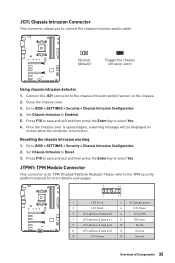
...Platform Module). Resetting the chassis intrusion warning 1. JCI1: Chassis Intrusion Connector This connector allows you to select Yes. 6. Connect the JCI1 connector to BIOS > SETTINGS > Security > Chassis Intrusion Configuration. 4. Go to the chassis intrusion switch/ sensor on . Press F10 to save and exit and ... Pin 11 LPC address & data pin3 12 Ground 13 LPC Frame 14 Ground Overview of Components 35 Go to BIOS > SETTINGS > Security > Chassis Intrusion Configuration. 2. Normal (default) Trigger the chassis intrusion event Using chassis intrusion detector 1.
...Platform Module). Resetting the chassis intrusion warning 1. JCI1: Chassis Intrusion Connector This connector allows you to select Yes. 6. Connect the JCI1 connector to BIOS > SETTINGS > Security > Chassis Intrusion Configuration. 4. Go to the chassis intrusion switch/ sensor on . Press F10 to save and exit and ... Pin 11 LPC address & data pin3 12 Ground 13 LPC Frame 14 Ground Overview of Components 35 Go to BIOS > SETTINGS > Security > Chassis Intrusion Configuration. 2. Normal (default) Trigger the chassis intrusion event Using chassis intrusion detector 1.

User Manual
Page 36
...: Parallel Port Connector This connector allows you want to clear the system configuration, set the jumper to default values 1. Keep Data (default) Clear CMOS/ Reset BIOS Resetting BIOS to clear the CMOS memory. If you to connect the optional parallel port with bracket. 2 26 1 25 1 RSTB# 2 AFD# 3 PRND0 4 ERR# 5 PRND1 6 PINIT# 7 PRND2... 17 PRND7 18 Ground 19 ACK# 20 Ground 21 BUSY 22 Ground 23 PE 24 Ground 25 SLCT 26 No Pin JBAT1: Clear CMOS (Reset BIOS) Jumper There is CMOS memory onboard that is external powered from JBAT1. 4.
...: Parallel Port Connector This connector allows you want to clear the system configuration, set the jumper to default values 1. Keep Data (default) Clear CMOS/ Reset BIOS Resetting BIOS to clear the CMOS memory. If you to connect the optional parallel port with bracket. 2 26 1 25 1 RSTB# 2 AFD# 3 PRND0 4 ERR# 5 PRND1 6 PINIT# 7 PRND2... 17 PRND7 18 Ground 19 ACK# 20 Ground 21 BUSY 22 Ground 23 PE 24 Ground 25 SLCT 26 No Pin JBAT1: Clear CMOS (Reset BIOS) Jumper There is CMOS memory onboard that is external powered from JBAT1. 4.

User Manual
Page 38
...Enter Memory-Z menu F6: Load optimized defaults F7: Switch between Yes or No to confirm your choice. 38 BIOS Setup Therefore, the description may vary from the latest BIOS and should always keep the default settings to avoid possible system damage or failure booting unless you purchased. You... could also refer to the HELP information panel for reference only. y The BIOS items will vary with BIOS. BIOS Setup The default settings offer the optimal performance for system stability in this chapter are for reference only and may be ...
...Enter Memory-Z menu F6: Load optimized defaults F7: Switch between Yes or No to confirm your choice. 38 BIOS Setup Therefore, the description may vary from the latest BIOS and should always keep the default settings to avoid possible system damage or failure booting unless you purchased. You... could also refer to the HELP information panel for reference only. y The BIOS items will vary with BIOS. BIOS Setup The default settings offer the optimal performance for system stability in this chapter are for reference only and may be ...

User Manual
Page 39
... reboot the system and enter the flash mode. 4. Updating the BIOS with M-FLASH Before updating: Please download the latest BIOS file that contains the update file into the USB flash drive. Install and launch MSI LIVE UPDATE 6. 2. Select BIOS Update. 3. BIOS Setup 39 Updating BIOS Updating BIOS with Live Update 6 Before updating: Make sure the LAN driver...
... reboot the system and enter the flash mode. 4. Updating the BIOS with M-FLASH Before updating: Please download the latest BIOS file that contains the update file into the USB flash drive. Install and launch MSI LIVE UPDATE 6. 2. Select BIOS Update. 3. BIOS Setup 39 Updating BIOS Updating BIOS with Live Update 6 Before updating: Make sure the LAN driver...
User Manual
Page 40
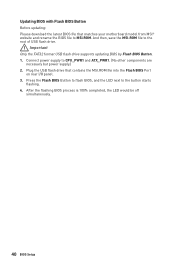
...Before updating: Please download the latest BIOS file that contains the MSI.ROM file into the Flash BIOS Port on rear I/O panel. 3. Connect power supply to MSI.ROM. Plug the USB flash drive that matches your motherboard model from MSI® website and rename the BIOS file to CPU_PWR1 and ATX_PWR1. (... are necessary but power supply.) 2. And then, save the MSI.ROM file to the button starts flashing. 4. Press the Flash BIOS Button to flash BIOS, and the LED next to the root of USB flash drive. After the flashing BIOS process is 100% completed, the LED would be off simultaneously....
...Before updating: Please download the latest BIOS file that contains the MSI.ROM file into the Flash BIOS Port on rear I/O panel. 3. Connect power supply to MSI.ROM. Plug the USB flash drive that matches your motherboard model from MSI® website and rename the BIOS file to CPU_PWR1 and ATX_PWR1. (... are necessary but power supply.) 2. And then, save the MSI.ROM file to the button starts flashing. 4. Press the Flash BIOS Button to flash BIOS, and the LED next to the root of USB flash drive. After the flashing BIOS process is 100% completed, the LED would be off simultaneously....

User Manual
Page 41
... Search - Important In search page, only the F6, F10 and F12 function keys are available. y System information - you to select the language of BIOS setup. click on it to USB flash drive (FAT/ FAT32 format only). y A-XMP switch (optional) - click on this tab or the F7 key...display M-Flash Favorites Hardware Monitor Function buttons y OC GENIE 4 switch - y Screenshot - y Language - To configure the advanced BIOS settings, please enter the Advanced Mode by BIOS item name, enter the item name to find the item listing. press this tab or the Ctrl+F keys and the search ...
... Search - Important In search page, only the F6, F10 and F12 function keys are available. y System information - you to select the language of BIOS setup. click on it to USB flash drive (FAT/ FAT32 format only). y A-XMP switch (optional) - click on this tab or the F7 key...display M-Flash Favorites Hardware Monitor Function buttons y OC GENIE 4 switch - y Screenshot - y Language - To configure the advanced BIOS settings, please enter the Advanced Mode by BIOS item name, enter the item name to find the item listing. press this tab or the Ctrl+F keys and the search ...

User Manual
Page 42
... ƒ Default HomePage - click on the CPU, Memory, Storage, Fan Info and Help buttons on their respective button. SETTINGS, OC...,etc) as the BIOS home page. ƒ Favorite1~5 - enable or disable the LAN Option ROM, HD audio controller, AHCI/RAID, CPU Fan Fail Warning Control, Windows 10 ...WHQL support and BIOS Log Review by percentage. click on search page. 2. y Hardware Monitor - Move the mouse over a BIOS item on OK. 42 BIOS Setup Choose a favorite page and click on this button to display the M-Flash menu ...
... ƒ Default HomePage - click on the CPU, Memory, Storage, Fan Info and Help buttons on their respective button. SETTINGS, OC...,etc) as the BIOS home page. ƒ Favorite1~5 - enable or disable the LAN Option ROM, HD audio controller, AHCI/RAID, CPU Fan Fail Warning Control, Windows 10 ...WHQL support and BIOS Log Review by percentage. click on search page. 2. y Hardware Monitor - Move the mouse over a BIOS item on OK. 42 BIOS Setup Choose a favorite page and click on this button to display the M-Flash menu ...

User Manual
Page 43
...specify the parameters for chipset and boot devices. ƒ OC - provides the information of EZ Mode Overview section. y BIOS menu selection - BIOS Setup 43 please refer to manage overclocking profiles. ƒ HARDWARE MONITOR - provides the way to be configured. the ...this motherboard. A-XMP switch Setup Mode switch Screenshot Search Language System information OC GENIE 4 switch Boot device priority bar BIOS menu selection BIOS menu selection Menu display y OC GENIE 4 switch/ Setup Mode switch/ Screenshot/ Language/ System information/ Boot device priority...
...specify the parameters for chipset and boot devices. ƒ OC - provides the information of EZ Mode Overview section. y BIOS menu selection - BIOS Setup 43 please refer to manage overclocking profiles. ƒ HARDWARE MONITOR - provides the way to be configured. the ...this motherboard. A-XMP switch Setup Mode switch Screenshot Search Language System information OC GENIE 4 switch Boot device priority bar BIOS menu selection BIOS menu selection Menu display y OC GENIE 4 switch/ Setup Mode switch/ Screenshot/ Language/ System information/ Boot device priority...

User Manual
Page 44
... power cable connections of connected SATA device. Use tab key to Sat, determined by BIOS. Press Enter to switch between time elements. Use tab key to enter the sub-menu. 44 BIOS Setup Important If the connected SATA device is . The format is . The date from... Jan. f System Information Shows detailed system information, including CPU type, BIOS version, and Memory (read only). Read-only. Advanced f PCI Subsystem Settings Sets PCI, PCI express interface protocol and latency timer. SETTINGS ...
... power cable connections of connected SATA device. Use tab key to Sat, determined by BIOS. Press Enter to switch between time elements. Use tab key to enter the sub-menu. 44 BIOS Setup Important If the connected SATA device is . The format is . The date from... Jan. f System Information Shows detailed system information, including CPU type, BIOS version, and Memory (read only). Read-only. Advanced f PCI Subsystem Settings Sets PCI, PCI express interface protocol and latency timer. SETTINGS ...

User Manual
Page 45
... Press Enter to enter the submenu. fIpv6 PXE Support [Enabled] When Enabled, the system UEFI network stack will support Ipv4 protocol. BIOS Setup 45 fAbove 4G memory/ Crypto Currency mining [Disabled] Enables or disables 64-bit capable devices to be decoded in this function...is Enabled. [Enabled] Enables UEFI network stack. [Disabled] Disables UEFI network stack. This item is available when Onboard LAN Controller is for MSI M.2 Xpander / MSI M.2 Xpander-Z / Other M.2 PCIe storage card. fIpv4 PXE Support [Enabled] When Enabled, the system UEFI network stack will support Ipv6 protocol...
... Press Enter to enter the submenu. fIpv6 PXE Support [Enabled] When Enabled, the system UEFI network stack will support Ipv4 protocol. BIOS Setup 45 fAbove 4G memory/ Crypto Currency mining [Disabled] Enables or disables 64-bit capable devices to be decoded in this function...is Enabled. [Enabled] Enables UEFI network stack. [Disabled] Disables UEFI network stack. This item is available when Onboard LAN Controller is for MSI M.2 Xpander / MSI M.2 Xpander-Z / Other M.2 PCIe storage card. fIpv4 PXE Support [Enabled] When Enabled, the system UEFI network stack will support Ipv6 protocol...

User Manual
Page 46
... detect if any USB device is connected and enable the legacy USB support. [Enabled] Enable the USB support under legacy mode. 46 BIOS Setup fSATAx Hot Plug [Disabled] Allows user to enhance the speed and performance of the onboard SATA controller. [AHCI Mode] Specify the...the integrated graphics controller. fHD Audio Controller [Enabled] Enables or disables the onboard High Definition Audio controller. Press Enter to Force, BIOS will be available when Integrated Graphics is enabled. Press Enter to the onboard graphics. fUMA Frame Buffer Size [Auto] (optional) Selects a ...
... detect if any USB device is connected and enable the legacy USB support. [Enabled] Enable the USB support under legacy mode. 46 BIOS Setup fSATAx Hot Plug [Disabled] Allows user to enhance the speed and performance of the onboard SATA controller. [AHCI Mode] Specify the...the integrated graphics controller. fHD Audio Controller [Enabled] Enables or disables the onboard High Definition Audio controller. Press Enter to Force, BIOS will be available when Integrated Graphics is enabled. Press Enter to the onboard graphics. fUMA Frame Buffer Size [Auto] (optional) Selects a ...

User Manual
Page 47
... optimize the IRQ automatically or you can set it manually. If set to Auto, BIOS will optimize the IRQ automatically or you can set it manually. fErP Ready [Disabled] Enables or disables the system power consumption according to ErP regulation. [...Enabled] Optimize the system power consumption according to enter the sub-menu. BIOS Setup 47 fSerial (COM) Port0 Settings [Auto] Sets serial port 0. Press Enter to ErP regulation. It will not support S4 & S5 wake up the system...
... optimize the IRQ automatically or you can set it manually. If set to Auto, BIOS will optimize the IRQ automatically or you can set it manually. fErP Ready [Disabled] Enables or disables the system power consumption according to ErP regulation. [...Enabled] Optimize the system power consumption according to enter the sub-menu. BIOS Setup 47 fSerial (COM) Port0 Settings [Auto] Sets serial port 0. Press Enter to ErP regulation. It will not support S4 & S5 wake up the system...


