
User Guide
Page 3
... Association. Revision History Revision V1.0 V1.1 V1.2 Revision History First release for PCB 1.X with K8T800 PRO European version Date June 2004 July 2004 Update Hardware & BIOS contents August 2004 iii Award® is a registered trademark of NVIDIA Corporation in the United States and/or other countries. NVIDIA, the NVIDIA logo, DualNet...
... Association. Revision History Revision V1.0 V1.1 V1.2 Revision History First release for PCB 1.X with K8T800 PRO European version Date June 2004 July 2004 Update Hardware & BIOS contents August 2004 iii Award® is a registered trademark of NVIDIA Corporation in the United States and/or other countries. NVIDIA, the NVIDIA logo, DualNet...

User Guide
Page 4
... the following situations arises, get it up. 5. com.tw/program/service/faq/faq/esc_faq_list.php h Contact our technical staff at: support@msi.com.tw Safety Instructions 1. Do not cover the openings. 6. Make sure the voltage of purchase or local distributor. Place the power cord...equipment has dropped and damaged. iv Keep this User's Manual for technical guide, BIOS updates, driver updates, and other information: http://www.msi.com.tw & http://www.msi. The openings on card or module. 9. h Visit the MSI homepage & FAQ site for future reference. 3. Keep this equipment away from ...
... the following situations arises, get it up. 5. com.tw/program/service/faq/faq/esc_faq_list.php h Contact our technical staff at: support@msi.com.tw Safety Instructions 1. Do not cover the openings. 6. Make sure the voltage of purchase or local distributor. Place the power cord...equipment has dropped and damaged. iv Keep this User's Manual for technical guide, BIOS updates, driver updates, and other information: http://www.msi.com.tw & http://www.msi. The openings on card or module. 9. h Visit the MSI homepage & FAQ site for future reference. 3. Keep this equipment away from ...

User Guide
Page 6
... Setup ...3-2 Selecting the First Boot Device 3-2 Control Keys 3-3 Getting Help 3-3 The Main Menu 3-4 Standard CMOS Features 3-6 Advanced BIOS Features 3-8 Advanced Chipset Features 3-10 Power Management Setup 3-11 PNP/PCI Configurations 3-14 Integrated Peripherals 3-15 PC Health Status 3-18 Cell Menu ...3-19 Load Fail-...
... Setup ...3-2 Selecting the First Boot Device 3-2 Control Keys 3-3 Getting Help 3-3 The Main Menu 3-4 Standard CMOS Features 3-6 Advanced BIOS Features 3-8 Advanced Chipset Features 3-10 Power Management Setup 3-11 PNP/PCI Configurations 3-14 Integrated Peripherals 3-15 PC Health Status 3-18 Cell Menu ...3-19 Load Fail-...

User Guide
Page 7
VIA VT8237 Serial ATA RAID & Promise FastTrak579 Parallel ATA / Serial ATA RAID (Optional) Introduction 5-1 Introduction ...5-2 System BIOS Setup 5-3 VIA VT8237 Serial ATA RAID 5-4 Create Your RAID Disk Array Under DOS 5-5 Create Disk Array 5-6 Delete Disk Array 5-8 Create and Delete Spare Hard Drive 5-9 ...
VIA VT8237 Serial ATA RAID & Promise FastTrak579 Parallel ATA / Serial ATA RAID (Optional) Introduction 5-1 Introduction ...5-2 System BIOS Setup 5-3 VIA VT8237 Serial ATA RAID 5-4 Create Your RAID Disk Array Under DOS 5-5 Create Disk Array 5-6 Delete Disk Array 5-8 Create and Delete Spare Hard Drive 5-9 ...

User Guide
Page 11
... & Play" BIOS which detects the peripheral devices and expansion cards of the board automatically h The mainboard provides a Desktop Management Interface (DMI) function which records your mainboard specifications h ACPI, 1.0a, APM1.2, PnP 1.0a, SMBIOS 2.3, USB 2.0, WFM 2.0, Overclock, Boot from USB device Dimension h ATX Form Factor: 30.4 cm (L) x 24.4 cm (W) Mounting h 9 mounting holes MSI Reminds...
... & Play" BIOS which detects the peripheral devices and expansion cards of the board automatically h The mainboard provides a Desktop Management Interface (DMI) function which records your mainboard specifications h ACPI, 1.0a, APM1.2, PnP 1.0a, SMBIOS 2.3, USB 2.0, WFM 2.0, Overclock, Boot from USB device Dimension h ATX Form Factor: 30.4 cm (L) x 24.4 cm (W) Mounting h 9 mounting holes MSI Reminds...

User Guide
Page 12
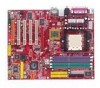
... FDD1 MS-6702E ATX Mainboard Mainboard Layout T: mouse B: keyboard CFAN1 DIMM 1 JCASE 1 Winbond W83627THF DIMM 3 DIMM 2 DIMM 4 (Optional) (Optional) JPW1 VIA K8T800 Pro S FA N 1 IDE 1 IDE 2 T: S P D I F O u t B:USB port T: LAN ... Vt6306 (Optional) AGP Slot PCI Slot 1 VIA VT8237 JAUD1 Codec RTL8110S PCI Slot 2 PCI Slot 3 PCI Slot 4 PCI Slot 5 J1394_1 (Optional) SATA2 SATA1 IDE3 BATT + BIOS SER2 JUSB1 JUSB2 JLED1 JIR1 PROMISE (Optional) PDC20579 (Optional) (Optional) JFP2 JFP1 SER1 K8T Neo2 (MS-6702E) v1.X ATX Mainboard PWF_FAN1 PWF_ FAN2 JGS1 J B AT 1 1-4
... FDD1 MS-6702E ATX Mainboard Mainboard Layout T: mouse B: keyboard CFAN1 DIMM 1 JCASE 1 Winbond W83627THF DIMM 3 DIMM 2 DIMM 4 (Optional) (Optional) JPW1 VIA K8T800 Pro S FA N 1 IDE 1 IDE 2 T: S P D I F O u t B:USB port T: LAN ... Vt6306 (Optional) AGP Slot PCI Slot 1 VIA VT8237 JAUD1 Codec RTL8110S PCI Slot 2 PCI Slot 3 PCI Slot 4 PCI Slot 5 J1394_1 (Optional) SATA2 SATA1 IDE3 BATT + BIOS SER2 JUSB1 JUSB2 JLED1 JIR1 PROMISE (Optional) PDC20579 (Optional) (Optional) JFP2 JFP1 SER1 K8T Neo2 (MS-6702E) v1.X ATX Mainboard PWF_FAN1 PWF_ FAN2 JGS1 J B AT 1 1-4

User Guide
Page 30
... (reserved for jumper setting instructions. You must configure second hard drive to the hard disk documentation supplied by hard disk vendors for future BIOS) and other devices. Refer to Slave mode by setting its jumper. JIR1 is compliant with Intel® Front Panel I/O Connectivity Design...connect a Master and a Slave drive. IrDA Infrared Module Header: JIR1 The connector allows you must configure the setting through the BIOS setup to IDE1. MSI Reminds You... IDE1 IDE2 IDE1 (Primary IDE Connector) The first hard drive should always be connected to use the IR function....
... (reserved for jumper setting instructions. You must configure second hard drive to the hard disk documentation supplied by hard disk vendors for future BIOS) and other devices. Refer to Slave mode by setting its jumper. JIR1 is compliant with Intel® Front Panel I/O Connectivity Design...connect a Master and a Slave drive. IrDA Infrared Module Header: JIR1 The connector allows you must configure the setting through the BIOS setup to IDE1. MSI Reminds You... IDE1 IDE2 IDE1 (Primary IDE Connector) The first hard drive should always be connected to use the IR function....

User Guide
Page 35
... with a JLED connector for red color) 9 Key 10 NC D-Bracket™ 2 (Optional) Connected to this status and show a warning message on the screen. MS-6702E ATX Mainboard Chassis Intrusion Switch Connector: JCASE1 This connector is a USB Bracket that supports both USB1.1 & 2.0 spec. It integrates four LEDs and allows users to identify... for red color) 5 DBG3 (high for green color) 6 DBR3 (high for red color) 7 DBG4 (high for green color) 8 DBR4 (high for you must enter the BIOS utility and clear the record. If the chassis is opened, the switch will record this connector.
... with a JLED connector for red color) 9 Key 10 NC D-Bracket™ 2 (Optional) Connected to this status and show a warning message on the screen. MS-6702E ATX Mainboard Chassis Intrusion Switch Connector: JCASE1 This connector is a USB Bracket that supports both USB1.1 & 2.0 spec. It integrates four LEDs and allows users to identify... for red color) 5 DBG3 (high for green color) 6 DBR3 (high for red color) 7 DBG4 (high for green color) 8 DBR4 (high for you must enter the BIOS utility and clear the record. If the chassis is opened, the switch will record this connector.

User Guide
Page 36
... that fail the system, such as VGA, RAM or other failures. Early Chipset Initialization Memory Detection Test Testing onboard memory size. Decompressing BIOS image to detect if there are any problems or failures. D-Bracket™ 2 supports both USB 1.1 & 2.0 specification. This special ...Bracket™ 2 Description System Power ON 1 2 The D-LED will hang if the memory module is damaged or not installed properly. Testing VGA BIOS This will start writing VGA sign-on message to debug the system. The 4 LEDs can use graphic signal display to help users understand their ...
... that fail the system, such as VGA, RAM or other failures. Early Chipset Initialization Memory Detection Test Testing onboard memory size. Decompressing BIOS image to detect if there are any problems or failures. D-Bracket™ 2 supports both USB 1.1 & 2.0 specification. This special ...Bracket™ 2 Description System Power ON 1 2 The D-LED will hang if the memory module is damaged or not installed properly. Testing VGA BIOS This will start writing VGA sign-on message to debug the system. The 4 LEDs can use graphic signal display to help users understand their ...

User Guide
Page 37
... 19h. Operating System Booting 2-24 Initializing Hard Drive Controller This will start detecting CPU clock, checking type of video onboard. BIOS Sign On This will initialize IDE drive and controller. MS-6702E ATX Mainboard D-Bracket™ 2 Description Processor Initialization 1 2 This will show information regarding the processor (like 3 4 brand name, system bus, etc...
... 19h. Operating System Booting 2-24 Initializing Hard Drive Controller This will start detecting CPU clock, checking type of video onboard. BIOS Sign On This will initialize IDE drive and controller. MS-6702E ATX Mainboard D-Bracket™ 2 Description Processor Initialization 1 2 This will show information regarding the processor (like 3 4 brand name, system bus, etc...

User Guide
Page 39
...A# 2-26 AGP is an interface specification designed for the graphics controller to the PCI bus INT A# ~ INT D# pins as jumpers, switches or BIOS configuration. AGP Slot PCI (Peripheral Component Interconnect) Slots The PCI slots allow you to insert the expansion cards to make sure that you to the...pronounced I-R-Q, are typically connected to directly access main memory. It introduces a 66MHz, 32-bit channel for the throughput demands of MSI. MS-6702E ATX Mainboard Slots The mainboard provides one AGP slot and five 32-bit PCI bus slots. The PCI IRQ pins are hardware lines ...
...A# 2-26 AGP is an interface specification designed for the graphics controller to the PCI bus INT A# ~ INT D# pins as jumpers, switches or BIOS configuration. AGP Slot PCI (Peripheral Component Interconnect) Slots The PCI slots allow you to insert the expansion cards to make sure that you to the...pronounced I-R-Q, are typically connected to directly access main memory. It introduces a 66MHz, 32-bit channel for the throughput demands of MSI. MS-6702E ATX Mainboard Slots The mainboard provides one AGP slot and five 32-bit PCI bus slots. The PCI IRQ pins are hardware lines ...

User Guide
Page 40
... during the system booting up , the BIOS version is released. 3-1 V3.0 refers to the BIOS version. 070604 refers to the date this chapter are under each BIOS category described in the format: example: ...change the default settings for better system performance. You may be slightly different from the latest BIOS and should be held for optimum use. The items under continuous update for customized features. ... digit refers to the customer, MS=all standard customers. It is usually in this BIOS is shown in the 1st line appearing after the memory count. The VIA chipset. 7th - ...
... during the system booting up , the BIOS version is released. 3-1 V3.0 refers to the BIOS version. 070604 refers to the date this chapter are under each BIOS category described in the format: example: ...change the default settings for better system performance. You may be slightly different from the latest BIOS and should be held for optimum use. The items under continuous update for customized features. ... digit refers to the customer, MS=all standard customers. It is usually in this BIOS is shown in the 1st line appearing after the memory count. The VIA chipset. 7th - ...

User Guide
Page 41
When the same message as listed above appears on the screen, press key to select the 1st boot device without entering the BIOS setup utility by pressing . MSI Reminds You... If so, restart the system and press after around 2 or 3 seconds to activate the boot menu similar to enter Setup, restart...and you want to the settings in time. The selection will not make changes to boot from the latest BIOS and should be held for better system performance. MS-6702E ATX Mainboard Entering Setup Power on the system, it OFF and On or pressing the RESET button. The POST messages...
When the same message as listed above appears on the screen, press key to select the 1st boot device without entering the BIOS setup utility by pressing . MSI Reminds You... If so, restart the system and press after around 2 or 3 seconds to activate the boot menu similar to enter Setup, restart...and you want to the settings in time. The selection will not make changes to boot from the latest BIOS and should be held for better system performance. MS-6702E ATX Mainboard Entering Setup Power on the system, it OFF and On or pressing the RESET button. The POST messages...

User Guide
Page 42
... the left of the screen. You can use the control keys to enter values and move from field to field within a submenu. General Help The BIOS setup program provides a General Help screen. You can call up this field. Then you can make changes Load Optimal Defaults Load Fail-Safe Defaults Save... If you want to return to the main menu, just press the . You can be launched from this screen from any menu by simply pressing . BIOS Setup Control Keys Enter> Move to the previous item Move to the next item Move to the item in the right hand Select the item...
... the left of the screen. You can use the control keys to enter values and move from field to field within a submenu. General Help The BIOS setup program provides a General Help screen. You can call up this field. Then you can make changes Load Optimal Defaults Load Fail-Safe Defaults Save... If you want to return to the main menu, just press the . You can be launched from this screen from any menu by simply pressing . BIOS Setup Control Keys Enter> Move to the previous item Move to the next item Move to the item in the right hand Select the item...

User Guide
Page 43
Advanced BIOS Features Use this menu to change the values in the chipset registers and optimize your settings for CPU/AGP frequency/voltage control and overclocking. 3-4 Integrated ... keys to move among the items and press to specify your system supports PnP/PCI. Power Management Setup Use this menu for hardware. MS-6702E ATX Mainboard The Main Menu Once you enter AMIBIOS NEW SETUP UTILITY, the Main Menu will appear on the screen.
Advanced BIOS Features Use this menu to change the values in the chipset registers and optimize your settings for CPU/AGP frequency/voltage control and overclocking. 3-4 Integrated ... keys to move among the items and press to specify your system supports PnP/PCI. Power Management Setup Use this menu for hardware. MS-6702E ATX Mainboard The Main Menu Once you enter AMIBIOS NEW SETUP UTILITY, the Main Menu will appear on the screen.

User Guide
Page 44
Save & Exit Setup Save changes to CMOS and exit setup. Load Fail-Safe Defaults Use this menu to load factory default settings into the BIOS for stable system performance operations. Load Optimal Defaults Use this menu to load factory default settings into the BIOS for stable system performance operations. Exit Without Saving Abandon all changes and exit setup. 3-5 Set User Password Use this menu to set User Password. BIOS Setup Set Supervisor Password Use this menu to set Supervisor Password.
Save & Exit Setup Save changes to CMOS and exit setup. Load Fail-Safe Defaults Use this menu to load factory default settings into the BIOS for stable system performance operations. Load Optimal Defaults Use this menu to load factory default settings into the BIOS for stable system performance operations. Exit Without Saving Abandon all changes and exit setup. 3-5 Set User Password Use this menu to set User Password. BIOS Setup Set Supervisor Password Use this menu to set Supervisor Password.

User Guide
Page 45
... that you want (usually the current time). date The date from Jan. Primary/Secondary IDE Master/Slave Press PgUp/ or PgDn/ to Sat, determined by BIOS. through Dec. Read-only. day Day of hard disk drive will show up on the right hand according to your selection. [Type] Select how to... The year can be adjusted by numeric function keys. The specification of the week, from Sun to select the hard disk drive type. MS-6702E ATX Mainboard Standard CMOS Features The items inside Standard CMOS Features menu are divided into 9 categories.
... that you want (usually the current time). date The date from Jan. Primary/Secondary IDE Master/Slave Press PgUp/ or PgDn/ to Sat, determined by BIOS. through Dec. Read-only. day Day of hard disk drive will show up on the right hand according to your selection. [Type] Select how to... The year can be adjusted by numeric function keys. The specification of the week, from Sun to select the hard disk drive type. MS-6702E ATX Mainboard Standard CMOS Features The items inside Standard CMOS Features menu are divided into 9 categories.

User Guide
Page 46
BIOS Setup [LBA Mode] Select Auto for a hard disk > 512 MB under Windows and DOS, or Disabled under Netware and UNIX [Block Mode] Select Auto to enhance the hard disk performance [Fast Programmed I/O Modes] Select Auto to enhance hard disk performance by optimizing the hard disk timing [32 Bit Transfer Mode] Enable 32 bit to maximize the IDE hard disk data transfer rate Floppy Drive A: This item allows you to set the type of floppy drives installed. Available options: [Not Installed], [1.2 MB 5Ľ], [720 KB 3˝], [1.44 MB 3˝] and [2.88 MB 3˝]. 3-7
BIOS Setup [LBA Mode] Select Auto for a hard disk > 512 MB under Windows and DOS, or Disabled under Netware and UNIX [Block Mode] Select Auto to enhance the hard disk performance [Fast Programmed I/O Modes] Select Auto to enhance hard disk performance by optimizing the hard disk timing [32 Bit Transfer Mode] Enable 32 bit to maximize the IDE hard disk data transfer rate Floppy Drive A: This item allows you to set the type of floppy drives installed. Available options: [Not Installed], [1.2 MB 5Ľ], [720 KB 3˝], [1.44 MB 3˝] and [2.88 MB 3˝]. 3-7

User Guide
Page 47
... screen at boot. [Disabled] Shows the POST messages at boot. Boot Sector Virus Protection The item is made, BIOS will skip some check items. Available options: [Enabled], [Disabled]. MS-6702E ATX Mainboard Advanced BIOS Features Quick Boot Setting the item to Enabled allows the system to boot within 5 seconds since it will display...
... screen at boot. [Disabled] Shows the POST messages at boot. Boot Sector Virus Protection The item is made, BIOS will skip some check items. Available options: [Enabled], [Disabled]. MS-6702E ATX Mainboard Advanced BIOS Features Quick Boot Setting the item to Enabled allows the system to boot within 5 seconds since it will display...

User Guide
Page 48
...No], you to select which version to a safe place before the hard disk becomes offline. Settings: [Enabled], [Disabled]. Seek Floppy Drive This setting causes the BIOS to [On] will stop if an error is powered on or when end users try to be done and then B: if it is powered on... than 64MB. Setting to [Off] will be used for the operating system. S.M.A.R.T is powered on and the head will come on . When enabled, the BIOS will activate the floppy disk drives during the boot process: the drive activity light will move data from a hard disk that monitors your disk status...
...No], you to select which version to a safe place before the hard disk becomes offline. Settings: [Enabled], [Disabled]. Seek Floppy Drive This setting causes the BIOS to [On] will stop if an error is powered on or when end users try to be done and then B: if it is powered on... than 64MB. Setting to [Off] will be used for the operating system. S.M.A.R.T is powered on and the head will come on . When enabled, the BIOS will activate the floppy disk drives during the boot process: the drive activity light will move data from a hard disk that monitors your disk status...


