
User Guide
Page 8
Hardware Setup 2-1 Quick Components Guide 2-2 CPU (Central Processing Unit 2-2 Memory ...2-6 Power Supply ...2-8 Back Panel ...2-9 Connectors ...2-11 Jumpers ...2-19 Slots ...2-20 Chapter 3 BIOS Setup 3-1 Entering Setup ...3-2 The Main Menu ...3-4 Standard CMOS Features 3-6 ...
Hardware Setup 2-1 Quick Components Guide 2-2 CPU (Central Processing Unit 2-2 Memory ...2-6 Power Supply ...2-8 Back Panel ...2-9 Connectors ...2-11 Jumpers ...2-19 Slots ...2-20 Chapter 3 BIOS Setup 3-1 Entering Setup ...3-2 The Main Menu ...3-4 Standard CMOS Features 3-6 ...

User Guide
Page 11
...) - Compliant with jack sensing - Supports 1 FDD with Fan Speed Control (For the latest information about CPU, please visit http://global.msi. Controlled by Realtek 8111B (optional) 1394 (Optional) - Supports 4 SATA devices - SATA1~4 support RAID 0/ 1/ 0+1mode 1-2 Supports 4 pin CPU Fan Pin-Header with 360KB, 720KB, 1.2MB, 1.44MB and 2.88MB RAID - t w / inde x . t w / inde x . Transfer rate...
...) - Compliant with jack sensing - Supports 1 FDD with Fan Speed Control (For the latest information about CPU, please visit http://global.msi. Controlled by Realtek 8111B (optional) 1394 (Optional) - Supports 4 SATA devices - SATA1~4 support RAID 0/ 1/ 0+1mode 1-2 Supports 4 pin CPU Fan Pin-Header with 360KB, 720KB, 1.2MB, 1.44MB and 2.88MB RAID - t w / inde x . t w / inde x . Transfer rate...

User Guide
Page 17
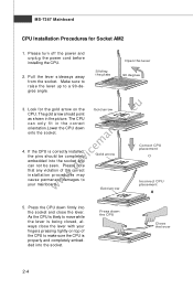
If you apply an even layer of CPU. 2-3 For the latest information about CPU, please visit http://global.msi.com.tw/index.php? func=cpuform www.devicemanuals.eu Important Overheating Overheating will seriously damage the CPU and system. Replaceing the CPU While replacing the CPU, always turn off the ATX power supply or unplug the power supply's power...
If you apply an even layer of CPU. 2-3 For the latest information about CPU, please visit http://global.msi.com.tw/index.php? func=cpuform www.devicemanuals.eu Important Overheating Overheating will seriously damage the CPU and system. Replaceing the CPU While replacing the CPU, always turn off the ATX power supply or unplug the power supply's power...
User Guide
Page 18
... properly and completely embedded into the socket. The gold arrow should be seen. Gold arrow Gold arrow Correct CPU placement O Incorrect CPU placement 5. Press the CPU down firmly into the socket and can only fit in the picture. Gold arrow 4. Press down onto the socket. Look for Socket AM2 1. ...Pull the lever sideways away from the socket. Sliding the plate Open the lever 90 degree www.devicemanuals.eu 3. The CPU can not be completely embedded into the socket and close the lever with your mainboard. Please note that any violation of the...
... properly and completely embedded into the socket. The gold arrow should be seen. Gold arrow Gold arrow Correct CPU placement O Incorrect CPU placement 5. Press the CPU down firmly into the socket and can only fit in the picture. Gold arrow 4. Press down onto the socket. Look for Socket AM2 1. ...Pull the lever sideways away from the socket. Sliding the plate Open the lever 90 degree www.devicemanuals.eu 3. The CPU can not be completely embedded into the socket and close the lever with your mainboard. Please note that any violation of the...

User Guide
Page 19
...eu 2. Hook one end of the clip to prevent overheating. Attach the CPU Fan cable to the CPU fan connector on the top of the retention mechanism. Read the CPU status in this section are installing the CPU, make sure the CPU has a heat sink and a cooling fan attached on the model you purchase...cooling set onto the retention mechanism. Locate the Fix Lever and lift up it . Hardware Setup Installing AMD Socket AM2 CPU Cooler Set W hen you are for demonstration of the CPU/ cooler installation only. Fasten down the other end of the clip to purchase and install them before turning on the...
...eu 2. Hook one end of the clip to prevent overheating. Attach the CPU Fan cable to the CPU fan connector on the top of the retention mechanism. Read the CPU status in this section are installing the CPU, make sure the CPU has a heat sink and a cooling fan attached on the model you purchase...cooling set onto the retention mechanism. Locate the Fix Lever and lift up it . Hardware Setup Installing AMD Socket AM2 CPU Cooler Set W hen you are for demonstration of the CPU/ cooler installation only. Fasten down the other end of the clip to purchase and install them before turning on the...
User Guide
Page 22
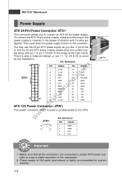
...JPW1 This power connector JPW 1 is highly recommended for system stability. 2-8 You may use the 20-pin ATX power supply, please plug your power sup- Power supply of the mainboard. 2. If you like to the CPU. JPW1 Pin Definition PIN SIGNAL 4 2 1 GND 3 1 2 GND 3 12V 4 12V pin 13 ...pin 12 Important 1. ply along with pin 1 & pin 13 (refer to connect an ATX 24-pin power supply. There is inserted in the proper ...
...JPW1 This power connector JPW 1 is highly recommended for system stability. 2-8 You may use the 20-pin ATX power supply, please plug your power sup- Power supply of the mainboard. 2. If you like to the CPU. JPW1 Pin Definition PIN SIGNAL 4 2 1 GND 3 1 2 GND 3 12V 4 12V pin 13 ...pin 12 Important 1. ply along with pin 1 & pin 13 (refer to connect an ATX 24-pin power supply. There is inserted in the proper ...

User Guide
Page 27
... W hen connecting the wire to the connectors, always note that will automatically control the CPU fan speed according to the recommended CPU fans at processor's official website or consult the vendors for proper CPU cooling fan. 2. the black wire is the positive and should be activated. Please refer... JCD1 2-13 If the chassis is provided for CPUFAN1. Chassis Intrusion Switch Connector: JCI1 This connector connects to take advantage of the CPU fan control. If the mainboard has a System Hardware Monitor chipset on-board, you must use a specially designed fan with +12V.
... W hen connecting the wire to the connectors, always note that will automatically control the CPU fan speed according to the recommended CPU fans at processor's official website or consult the vendors for proper CPU cooling fan. 2. the black wire is the positive and should be activated. Please refer... JCD1 2-13 If the chassis is provided for CPUFAN1. Chassis Intrusion Switch Connector: JCI1 This connector connects to take advantage of the CPU fan control. If the mainboard has a System Hardware Monitor chipset on-board, you must use a specially designed fan with +12V.

User Guide
Page 42
.../ BIOS Version/ M emory Information These items show the CPU information, BIOS version and memory status of floppy drives installed. System Information Press to Auto enables LBA mode if the device supports it and the ...
.../ BIOS Version/ M emory Information These items show the CPU information, BIOS version and memory status of floppy drives installed. System Information Press to Auto enables LBA mode if the device supports it and the ...

User Guide
Page 48
.... Power Management Setup BIOS Setup www.devicemanuals.eu Important S3-related functions described in this section are : [S1/POS] The S1 sleep mode is lost (CPU or chipset) and hardware main- If your operating system is ACPI-aware, such as W indows 2000/ XP , you can choose to enter the Standby mode...
.... Power Management Setup BIOS Setup www.devicemanuals.eu Important S3-related functions described in this section are : [S1/POS] The S1 sleep mode is lost (CPU or chipset) and hardware main- If your operating system is ACPI-aware, such as W indows 2000/ XP , you can choose to enter the Standby mode...
User Guide
Page 49
..., the computer enters the suspend/sleep mode, but if the button is pressed for the length of time specified in this field, all devices except CPU will reboot after a power failure or interrupt www.devicemanuals.eu occurs. Restores the system to power on the system. Resume by PCI Device (PME#) W hen...
..., the computer enters the suspend/sleep mode, but if the button is pressed for the length of time specified in this field, all devices except CPU will reboot after a power failure or interrupt www.devicemanuals.eu occurs. Restores the system to power on the system. Resume by PCI Device (PME#) W hen...
User Guide
Page 51
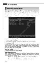
....eu Primary Graphic's Adapter This setting specifies which allows I/O devices to higher values. W hen set the item to operate at speeds nearing the speed the CPU itself uses when communicating with its special components. This section covers some very technical items and it is your primary graphics adapter. PCI Slot 1/2 IRQ...
....eu Primary Graphic's Adapter This setting specifies which allows I/O devices to higher values. W hen set the item to operate at speeds nearing the speed the CPU itself uses when communicating with its special components. This section covers some very technical items and it is your primary graphics adapter. PCI Slot 1/2 IRQ...

User Guide
Page 53
...function if you do not have any EMI problem, leave the setting at [Disabled] for EMI reduction. Cool'n'Quiet It provides a CPU temperature detecting function to prevent your overclocked processor to lock up. Chassis Intrusion The field enables or disables the feature of the field ...and performance. Auto Disable DIMM/ PCI Clock This item is once opened. MS-7367 Mainboard H/W Monitor www.devicemanuals.eu Spread Spectrum W hen the motherboard's clock generator pulses, the extreme values (spikes) of the pulses are reduced to flatter curves. If you are overclocking, because even a slight...
...function if you do not have any EMI problem, leave the setting at [Disabled] for EMI reduction. Cool'n'Quiet It provides a CPU temperature detecting function to prevent your overclocked processor to lock up. Chassis Intrusion The field enables or disables the feature of the field ...and performance. Auto Disable DIMM/ PCI Clock This item is once opened. MS-7367 Mainboard H/W Monitor www.devicemanuals.eu Spread Spectrum W hen the motherboard's clock generator pulses, the extreme values (spikes) of the pulses are reduced to flatter curves. If you are overclocking, because even a slight...

User Guide
Page 54
PC Health Status Press to keep it with in a specific range. BIOS Setup Smart Fan Target The mainboard provides the Smart Fan system which can control the fan speed automatically depending on the current temperature to enter the sub-menu and following screen appears. www.devicemanuals.eu CPU/System Temperature, CPU FAN/ SYSTEM FAN Speed, CPU Vcore, 3.3VCC, 5V, 12V, 3.3V SB These items display the current status of all of the monitored hardware devices/ components such as CPU voltage, temperatures and all fans' speeds. 3-19
PC Health Status Press to keep it with in a specific range. BIOS Setup Smart Fan Target The mainboard provides the Smart Fan system which can control the fan speed automatically depending on the current temperature to enter the sub-menu and following screen appears. www.devicemanuals.eu CPU/System Temperature, CPU FAN/ SYSTEM FAN Speed, CPU Vcore, 3.3VCC, 5V, 12V, 3.3V SB These items display the current status of all of the monitored hardware devices/ components such as CPU voltage, temperatures and all fans' speeds. 3-19

