
User Manual
Page 1
Preparing Tools and Components AMD® AM4 CPU CPU Fan DDR4 Memory Power Supply Unit Chassis Graphics Card Thermal Paste SATA Hard Disk Drive SATA DVD Drive Phillips Screwdriver A Package of the installations also provide video demonstrations. You may ... web browser on your computer. Please link to the URL to the URL by scanning the QR code. Quick Start Thank you for purchasing the MSI® MEG X570 UNIFY motherboard. Some of Screws Quick Start 1 This Quick Start section provides demonstration diagrams about how to install your phone or tablet.
Preparing Tools and Components AMD® AM4 CPU CPU Fan DDR4 Memory Power Supply Unit Chassis Graphics Card Thermal Paste SATA Hard Disk Drive SATA DVD Drive Phillips Screwdriver A Package of the installations also provide video demonstrations. You may ... web browser on your computer. Please link to the URL to the URL by scanning the QR code. Quick Start Thank you for purchasing the MSI® MEG X570 UNIFY motherboard. Some of Screws Quick Start 1 This Quick Start section provides demonstration diagrams about how to install your phone or tablet.

User Manual
Page 2
... turning on the computer, ensure that all components are securely connected. y Always turn off the power supply and unplug the power cord from electrostatic discharge (ESD). Do not place anything over the power cord. y Do not leave this package are no loose screws or metal components on the motherboard...start. y Do not boot the computer before connecting the PSU to damage from the power outlet before handling the motherboard. This could cause permanent damage to the user. y Place the power cord such a way that your electrical outlet provides the same voltage as injury to ...
... turning on the computer, ensure that all components are securely connected. y Always turn off the power supply and unplug the power cord from electrostatic discharge (ESD). Do not place anything over the power cord. y Do not leave this package are no loose screws or metal components on the motherboard...start. y Do not boot the computer before connecting the PSU to damage from the power outlet before handling the motherboard. This could cause permanent damage to the user. y Place the power cord such a way that your electrical outlet provides the same voltage as injury to ...

User Manual
Page 33
... graphics card, you need to use a tool such as MSI Gaming Series Graphics Card Bolster to support its weight to prevent deformation of Components 33 yyWhen adding or removing expansion cards, always turn off the power supply and unplug the power supply power cable from the power outlet. For 3rd Gen AMD Ryzen™ Slot Single 2-Way...
... graphics card, you need to use a tool such as MSI Gaming Series Graphics Card Bolster to support its weight to prevent deformation of Components 33 yyWhen adding or removing expansion cards, always turn off the power supply and unplug the power supply power cable from the power outlet. For 3rd Gen AMD Ryzen™ Slot Single 2-Way...
User Manual
Page 35
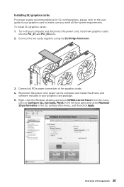
... in the SLI configuration menu, and then click Apply. Turn off your graphics card package. 5. Overview of the graphics cards. 4. Installing SLI graphics cards For power supply recommendations for SLI configurations, please refer to the user guide of your graphics card to make sure you meet all PCIe... power connectors of Components 35 Connect the two cards together using the SLI Bridge Connector. 3. Right-click the Windows desktop and select NVIDIA Control Panel from ...
... in the SLI configuration menu, and then click Apply. Turn off your graphics card package. 5. Overview of the graphics cards. 4. Installing SLI graphics cards For power supply recommendations for SLI configurations, please refer to the user guide of your graphics card to make sure you meet all PCIe... power connectors of Components 35 Connect the two cards together using the SLI Bridge Connector. 3. Right-click the Windows desktop and select NVIDIA Control Panel from ...

User Manual
Page 39
JAUD1: Front Audio Connector This connector allows you to connect an ATX power supply. 8 5 CPU_PWR1~2 4 1 1 Ground 5 2 Ground 6 3 Ground 7 4 Ground 8 +12V +12V +12V +12V 1 +3.3V 13 2 +3.3V 14 3 Ground 15 12 24 4 +5V 16 5 Ground 17 6 ... 12 +3.3V 24 +3.3V -12V Ground PS-ON# Ground Ground Ground Res +5V +5V +5V Ground Important Make sure that all the power cables are securely connected to a proper ATX power supply to connect audio jacks on the front panel. 2 10 1 9 1 MIC L 2 Ground 3 MIC R 4 NC 5 Head Phone R 6 MIC Detection 7 ...
JAUD1: Front Audio Connector This connector allows you to connect an ATX power supply. 8 5 CPU_PWR1~2 4 1 1 Ground 5 2 Ground 6 3 Ground 7 4 Ground 8 +12V +12V +12V +12V 1 +3.3V 13 2 +3.3V 14 3 Ground 15 12 24 4 +5V 16 5 Ground 17 6 ... 12 +3.3V 24 +3.3V -12V Ground PS-ON# Ground Ground Ground Res +5V +5V +5V Ground Important Make sure that all the power cables are securely connected to a proper ATX power supply to connect audio jacks on the front panel. 2 10 1 9 1 MIC L 2 Ground 3 MIC R 4 NC 5 Head Phone R 6 MIC Detection 7 ...

User Manual
Page 45
yyPlease use MSI's software to 2 meters continuous 5050 RGB LED strips (12V/G/R/B) with the maximum power rating of Components 45 JRGB1: RGB LED connector The JRGB connector allows you to connect the 5050 RGB LED strips 12V. 1 1 +12V 2 G 3 R 4 B RGB LED Strip ... Fan connector RGB LED Fan Important yyThe JRGB connector supports up to control the extended LED strip. Overview of 3A (12V). yyAlways turn off the power supply and unplug the power cord from the power outlet before installing or removing the RGB LED strip.
yyPlease use MSI's software to 2 meters continuous 5050 RGB LED strips (12V/G/R/B) with the maximum power rating of Components 45 JRGB1: RGB LED connector The JRGB connector allows you to connect the 5050 RGB LED strips 12V. 1 1 +12V 2 G 3 R 4 B RGB LED Strip ... Fan connector RGB LED Fan Important yyThe JRGB connector supports up to control the extended LED strip. Overview of 3A (12V). yyAlways turn off the power supply and unplug the power cord from the power outlet before installing or removing the RGB LED strip.

User Manual
Page 46
... JRGB connector will result in damage to control the extended LED strip. 46 Overview of Components yyPlease use MSI's software to the LED strip. yyAlways turn off the power supply and unplug the power cord from the power outlet before installing or removing the RGB LED strip. In the case of 20% brightness, the connector.... JRAINBOW1~2: Addressable RGB LED connectors The JRAINBOW connectors allow you to 75 LEDs WS2812B Individually Addressable RGB LED strips (5V/Data/Ground) with the maximum power rating of 3A (5V).
... JRGB connector will result in damage to control the extended LED strip. 46 Overview of Components yyPlease use MSI's software to the LED strip. yyAlways turn off the power supply and unplug the power cord from the power outlet before installing or removing the RGB LED strip. In the case of 20% brightness, the connector.... JRAINBOW1~2: Addressable RGB LED connectors The JRAINBOW connectors allow you to 75 LEDs WS2812B Individually Addressable RGB LED strips (5V/Data/Ground) with the maximum power rating of 3A (5V).

User Manual
Page 57
... button LED starts flashing. 4. Plug the USB flash drive that matches your motherboard model from MSI® website and rename the BIOS file to CPU_PWR1 and ATX_PWR1. (No other components are necessary but power supply.) 2. BIOS Setup 57 After the flashing BIOS process is 100% completed, the LED would be... off simultaneously. Important Only the FAT32 format USB flash drive supports updating BIOS by Flash BIOS Button. 1. Connect power supply to MSI.ROM. Updating BIOS with Flash BIOS Button Before updating: Please download the latest BIOS file that contains the...
... button LED starts flashing. 4. Plug the USB flash drive that matches your motherboard model from MSI® website and rename the BIOS file to CPU_PWR1 and ATX_PWR1. (No other components are necessary but power supply.) 2. BIOS Setup 57 After the flashing BIOS process is 100% completed, the LED would be... off simultaneously. Important Only the FAT32 format USB flash drive supports updating BIOS by Flash BIOS Button. 1. Connect power supply to MSI.ROM. Updating BIOS with Flash BIOS Button Before updating: Please download the latest BIOS file that contains the...

User Manual
Page 72
...EMI, select the value of CPU Base clock. ffSVM Mode [Enabled] Enables/ disables the AMD SVM (Secure Virtual Machine) Mode. ffPower Supply Idle Control [Auto] (optional) It allows you are overclocking because even a slight jitter can effectively and dynamically lower CPU speed and... power consumption. yyRemember to disable Spread Spectrum if you to select the power-saving control mode for the CPU when all C2P/P2C mailbox, Secure S3, fTPM support. ffBIOS PSP Support ...
...EMI, select the value of CPU Base clock. ffSVM Mode [Enabled] Enables/ disables the AMD SVM (Secure Virtual Machine) Mode. ffPower Supply Idle Control [Auto] (optional) It allows you are overclocking because even a slight jitter can effectively and dynamically lower CPU speed and... power consumption. yyRemember to disable Spread Spectrum if you to select the power-saving control mode for the CPU when all C2P/P2C mailbox, Secure S3, fTPM support. ffBIOS PSP Support ...
User Manual
Page 85
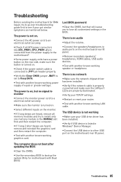
...monitor is no network y Make sure the network chipset driver has been installed. y If 1 long 2 short beeps are connected from the power supply to install only one memory module in the DIMMA2 slot first and then restart the computer. y Test with another known working graphics card. ... CMOS. y Check if all customized settings in Windows® Device Manager. y Some power supply units have a power button on . y Verify the Clear CMOS jumper JBAT1 is connected to lose all ATX power connectors like ATX_PWR1, CPU_PWR1~2 are heard, remove and reinstall the graphics card and then ...
...monitor is no network y Make sure the network chipset driver has been installed. y If 1 long 2 short beeps are connected from the power supply to install only one memory module in the DIMMA2 slot first and then restart the computer. y Test with another known working graphics card. ... CMOS. y Check if all customized settings in Windows® Device Manager. y Some power supply units have a power button on . y Verify the Clear CMOS jumper JBAT1 is connected to lose all ATX power connectors like ATX_PWR1, CPU_PWR1~2 are heard, remove and reinstall the graphics card and then ...

