User Manual
Page 13
JCOM1: Serial Port Connector 39 JBAT1: Clear CMOS (Reset BIOS) Jumper 40 JTBT1: Thunderbolt Add-on Card Connector 40 JRTD3: Intel RTD3 Connector 40 JRGB1: RGB LED connector 41 JRAINBOW1~2: Addressable RGB LED connectors 42 ... LED Control 44 Installing OS, Drivers & Utilities 45 Installing Windows® 10 45 Installing Drivers 45 Installing Utilities 45 UEFI BIOS...46 BIOS Setup...47 Entering BIOS Setup 47 Resetting BIOS...48 Updating BIOS...48 EZ Mode ...50 Advanced Mode ...53 SETTINGS Menu 54 OC Menu...56 M-FLASH Menu ...60 OC PROFILE Menu 61 HARDWARE...
JCOM1: Serial Port Connector 39 JBAT1: Clear CMOS (Reset BIOS) Jumper 40 JTBT1: Thunderbolt Add-on Card Connector 40 JRTD3: Intel RTD3 Connector 40 JRGB1: RGB LED connector 41 JRAINBOW1~2: Addressable RGB LED connectors 42 ... LED Control 44 Installing OS, Drivers & Utilities 45 Installing Windows® 10 45 Installing Drivers 45 Installing Utilities 45 UEFI BIOS...46 BIOS Setup...47 Entering BIOS Setup 47 Resetting BIOS...48 Updating BIOS...48 EZ Mode ...50 Advanced Mode ...53 SETTINGS Menu 54 OC Menu...56 M-FLASH Menu ...60 OC PROFILE Menu 61 HARDWARE...
User Manual
Page 15
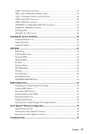
Storage RAID USB Audio LAN Continued from MSI website. Intel® Z490 Chipset ∙∙Supports RAID 0, RAID 1, RAID 5 and ...; Optane™ memory modules, please ensure that you have updated the drivers and BIOS to the latest version from previous page Intel® Z490 Chipset ∙∙6x SATA 6Gb/s ports*/** ∙∙2x M.2 slots (... Memory Ready*** ▪▪Supports Intel® Smart Response Technology for M.2 PCIe storage devices ∙∙Intel® Z490 Chipset ▪▪5x USB 3.2 Gen 2 10Gbps ports (4 Type-A ports on the back panel, 1 Type-C internal...
Storage RAID USB Audio LAN Continued from MSI website. Intel® Z490 Chipset ∙∙Supports RAID 0, RAID 1, RAID 5 and ...; Optane™ memory modules, please ensure that you have updated the drivers and BIOS to the latest version from previous page Intel® Z490 Chipset ∙∙6x SATA 6Gb/s ports*/** ∙∙2x M.2 slots (... Memory Ready*** ▪▪Supports Intel® Smart Response Technology for M.2 PCIe storage devices ∙∙Intel® Z490 Chipset ▪▪5x USB 3.2 Gen 2 10Gbps ports (4 Type-A ports on the back panel, 1 Type-C internal...

User Manual
Page 17
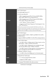
x 9.6 in . Continued from previous page LED Features Back Panel Connectors I/O Controller Hardware Monitor Form Factor BIOS Features Software ∙∙1x EZ LED Control switch ∙∙4x EZ Debug LED ∙∙1 x PS/2 keyboard/ mouse combo port ...8729;1x 256 Mb flash ∙∙UEFI AMI BIOS ∙∙ACPI 6.2, SMBIOS 3.2 ∙∙ Multi-language ∙∙ Drivers ∙∙DRAGON CENTER ∙∙MSI APP Player (BlueStacks) ∙∙Open Broadcaster Software (OBS) ∙∙CPU-Z MSI GAMING ∙∙Intel® Extreme Tuning Utility &#...
x 9.6 in . Continued from previous page LED Features Back Panel Connectors I/O Controller Hardware Monitor Form Factor BIOS Features Software ∙∙1x EZ LED Control switch ∙∙4x EZ Debug LED ∙∙1 x PS/2 keyboard/ mouse combo port ...8729;1x 256 Mb flash ∙∙UEFI AMI BIOS ∙∙ACPI 6.2, SMBIOS 3.2 ∙∙ Multi-language ∙∙ Drivers ∙∙DRAGON CENTER ∙∙MSI APP Player (BlueStacks) ∙∙Open Broadcaster Software (OBS) ∙∙CPU-Z MSI GAMING ∙∙Intel® Extreme Tuning Utility &#...
User Manual
Page 19
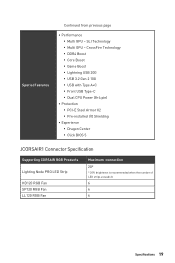
...9642;▪Multi GPU - SLI Technology ▪▪Multi GPU - CrossFire Technology ▪▪DDR4 Boost ▪▪Core Boost ▪▪Game Boost ▪▪Lightning USB 20G ▪▪USB 3.2 Gen 2 10G ▪▪USB with Type A+C ▪▪Front USB Type...;▪PCI-E Steel Armor X2 ▪▪Pre-installed I/O Shielding ∙∙ Experience ▪▪Dragon Center ▪▪Click BIOS 5 JCORSAIR1 Connector Specification Supporting CORSAIR RGB Products Lighting Node PRO LED Strip HD120 RGB Fan SP120 RGB Fan LL120 RGB Fan Maximum connection 20...
...9642;▪Multi GPU - SLI Technology ▪▪Multi GPU - CrossFire Technology ▪▪DDR4 Boost ▪▪Core Boost ▪▪Game Boost ▪▪Lightning USB 20G ▪▪USB 3.2 Gen 2 10G ▪▪USB with Type A+C ▪▪Front USB Type...;▪PCI-E Steel Armor X2 ▪▪Pre-installed I/O Shielding ∙∙ Experience ▪▪Dragon Center ▪▪Click BIOS 5 JCORSAIR1 Connector Specification Supporting CORSAIR RGB Products Lighting Node PRO LED Strip HD120 RGB Fan SP120 RGB Fan LL120 RGB Fan Maximum connection 20...

User Manual
Page 27
...~6 Fan Connectors CPU_PWR1~2, ATX_PWR1 Power Connectors CPU Socket LGA 1200 socket DIMM Slots DIMMA1, DIMMA2, DIMMB1, DIMMB2 JAUD1 Front Audio Connector JBAT1 Clear CMOS (Reset BIOS) Jumper JCI1 Chassis Intrusion Connector JCOM1 Serial Port Connector JCORSAIR1 CORSAIR Connector JFP1, JFP2 Front Panel Connectors JRAINBOW1~2 Addressable RGB LED connectors JRGB1 RGB LED...
...~6 Fan Connectors CPU_PWR1~2, ATX_PWR1 Power Connectors CPU Socket LGA 1200 socket DIMM Slots DIMMA1, DIMMA2, DIMMB1, DIMMB2 JAUD1 Front Audio Connector JBAT1 Clear CMOS (Reset BIOS) Jumper JCI1 Chassis Intrusion Connector JCOM1 Serial Port Connector JCORSAIR1 CORSAIR Connector JFP1, JFP2 Front Panel Connectors JRAINBOW1~2 Addressable RGB LED connectors JRGB1 RGB LED...
User Manual
Page 29
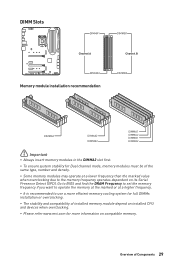
Overview of installed memory module depend on installed CPU and devices when overclocking. ∙∙Please refer www.msi.com for more information on its Serial Presence Detect (SPD). Go to BIOS and find the DRAM Frequency to set the memory frequency if you want to operate the memory at the marked or...
Overview of installed memory module depend on installed CPU and devices when overclocking. ∙∙Please refer www.msi.com for more information on its Serial Presence Detect (SPD). Go to BIOS and find the DRAM Frequency to set the memory frequency if you want to operate the memory at the marked or...

User Manual
Page 38
... mode) 1 SYS_FAN4, 5 (DC mode) Switching fan mode and adjusting fan speed You can switch between PWM mode and DC mode and adjust fan speed in BIOS > HARDWARE MONITOR. DC Mode fan connectors control fan speed by changing voltage.
... mode) 1 SYS_FAN4, 5 (DC mode) Switching fan mode and adjusting fan speed You can switch between PWM mode and DC mode and adjust fan speed in BIOS > HARDWARE MONITOR. DC Mode fan connectors control fan speed by changing voltage.

User Manual
Page 39
...3 SOUT 4 DTR 5 Ground 6 DSR 7 RTS 8 CTS 9 RI 10 No Pin Overview of Components 39 Close the chassis cover. 3. Go to Enabled. 5. Set Chassis Intrusion to BIOS > SETTINGS > Security > Chassis Intrusion Configuration. 4. Resetting the chassis intrusion warning 1. Go to select Yes. 6. JCOM1: Serial Port Connector This connector allows you to the chassis... event Using chassis intrusion detector 1. Set Chassis Intrusion to select Yes. Press F10 to save and exit and then press the Enter key to BIOS > SETTINGS > Security > Chassis Intrusion Configuration. 2.
...3 SOUT 4 DTR 5 Ground 6 DSR 7 RTS 8 CTS 9 RI 10 No Pin Overview of Components 39 Close the chassis cover. 3. Go to Enabled. 5. Set Chassis Intrusion to BIOS > SETTINGS > Security > Chassis Intrusion Configuration. 4. Resetting the chassis intrusion warning 1. Go to select Yes. 6. JCOM1: Serial Port Connector This connector allows you to the chassis... event Using chassis intrusion detector 1. Set Chassis Intrusion to select Yes. Press F10 to save and exit and then press the Enter key to BIOS > SETTINGS > Security > Chassis Intrusion Configuration. 2.

User Manual
Page 40
...-on Thunderbolt I /O card that is external powered from JBAT1. 4. Plug the power cord and Power on the motherboard to default values 1. JBAT1: Clear CMOS (Reset BIOS) Jumper There is CMOS memory onboard that supports RTD3. 1 JTBT1 1 FORCE_PWR 2 3 SLP_S3# 4 5 Ground SCI_EVENT SLP_S5# 1 JRTD3 1 WAKE 2 PWR EN 3 GND 40 Overview of Components If... you want to clear the system configuration, set the jumpers to short JBAT1 for about 5-10 seconds. 3. Keep Data (default) Clear CMOS/ Reset BIOS Resetting BIOS to save system configuration data.
...-on Thunderbolt I /O card that is external powered from JBAT1. 4. Plug the power cord and Power on the motherboard to default values 1. JBAT1: Clear CMOS (Reset BIOS) Jumper There is CMOS memory onboard that supports RTD3. 1 JTBT1 1 FORCE_PWR 2 3 SLP_S3# 4 5 Ground SCI_EVENT SLP_S5# 1 JRTD3 1 WAKE 2 PWR EN 3 GND 40 Overview of Components If... you want to clear the system configuration, set the jumpers to short JBAT1 for about 5-10 seconds. 3. Keep Data (default) Clear CMOS/ Reset BIOS Resetting BIOS to save system configuration data.

User Manual
Page 46
... at the top of the new chipset's capabilities. That allows you to CSM mode during the transition. ⚠⚠Important The term BIOS in the future. UEFI BIOS MSI UEFI BIOS is no malware tampers with the startup process. UEFI has many new functions and advantages that you to replace legacy devices with UEFI...
... at the top of the new chipset's capabilities. That allows you to CSM mode during the transition. ⚠⚠Important The term BIOS in the future. UEFI BIOS MSI UEFI BIOS is no malware tampers with the startup process. UEFI has many new functions and advantages that you to replace legacy devices with UEFI...

User Manual
Page 47
... the default settings to confirm your choice. Ctrl+F: Enter Search page * When you purchased. ∙∙The BIOS items will vary with BIOS. ⚠⚠Important ∙∙BIOS items are continuously update for reference only and may be for system stability in this chapter are familiar with the ...processor. UEFI BIOS 47 Function key F1: General Help list F2: Add/ Remove a favorite item F3: Enter Favorites menu F4: Enter CPU Specifications menu F5: ...
... the default settings to confirm your choice. Ctrl+F: Enter Search page * When you purchased. ∙∙The BIOS items will vary with BIOS. ⚠⚠Important ∙∙BIOS items are continuously update for reference only and may be for system stability in this chapter are familiar with the ...processor. UEFI BIOS 47 Function key F1: General Help list F2: Add/ Remove a favorite item F3: Enter Favorites menu F4: Enter CPU Specifications menu F5: ...

User Manual
Page 48
... the USB flash drive that matches your motherboard model from MSI website. Resetting BIOS You might need to restore the default BIOS setting to solve certain problems. There are several ways to reset BIOS: ∙∙Go to BIOS and press F6 to load optimized defaults. ∙∙Short the Clear...9888;Important Be sure the computer is 100% completed, the system will reboot automatically. 48 UEFI BIOS Updating BIOS: 1. Click the M-FLASH button and click on Yes to reboot the system. And then save the BIOS file into the USB port. 2. Please refer to the Clear CMOS jumper section for...
... the USB flash drive that matches your motherboard model from MSI website. Resetting BIOS You might need to restore the default BIOS setting to solve certain problems. There are several ways to reset BIOS: ∙∙Go to BIOS and press F6 to load optimized defaults. ∙∙Short the Clear...9888;Important Be sure the computer is 100% completed, the system will reboot automatically. 48 UEFI BIOS Updating BIOS: 1. Click the M-FLASH button and click on Yes to reboot the system. And then save the BIOS file into the USB port. 2. Please refer to the Clear CMOS jumper section for...
User Manual
Page 49
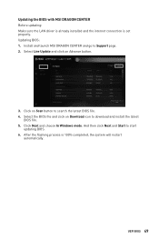
...the flashing process is set properly. Updating BIOS: 1. Select the BIOS file and click on Advance button. 3. And then click Next and Start to search the latest BIOS file. 4. Click on Scan button to start updating BIOS. 6. Install and launch MSI DRAGON CENTER and go to download and ...install the latest BIOS file. 5. Updating the BIOS with MSI DRAGON CENTER Before updating: Make sure the LAN driver is...
...the flashing process is set properly. Updating BIOS: 1. Select the BIOS file and click on Advance button. 3. And then click Next and Start to search the latest BIOS file. 4. Click on Scan button to start updating BIOS. 6. Install and launch MSI DRAGON CENTER and go to download and ...install the latest BIOS file. 5. Updating the BIOS with MSI DRAGON CENTER Before updating: Make sure the LAN driver is...

User Manual
Page 50
... both of the motherboard and CPU are available. 50 UEFI BIOS press this function. ∙∙ Setup Mode switch - To configure the advanced BIOS settings, please enter the Advanced Mode by BIOS item name. XMP Profile Screenshot Setup Mode switch Search Language System information GAME BOOST Boot device priority bar Component Information M-Flash Favorites...
... both of the motherboard and CPU are available. 50 UEFI BIOS press this function. ∙∙ Setup Mode switch - To configure the advanced BIOS settings, please enter the Advanced Mode by BIOS item name. XMP Profile Screenshot Setup Mode switch Search Language System information GAME BOOST Boot device priority bar Component Information M-Flash Favorites...
User Manual
Page 51
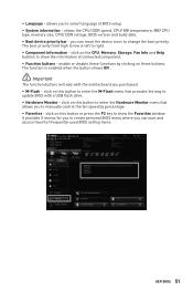
... The function buttons will vary with a USB flash drive. ∙∙ Hardware Monitor - The function is left to show the information of BIOS setup. ∙∙ System information - click on this button to enter the Hardware Monitor menu that provides the way to create personal... right. ∙∙ Component Information - shows the CPU/ DDR speed, CPU/ MB temperature, MB/ CPU type, memory size, CPU/ DDR voltage, BIOS version and build date. ∙∙ Boot device priority bar - click on this button to enter the M-Flash menu that allows you to manually control...
... The function buttons will vary with a USB flash drive. ∙∙ Hardware Monitor - The function is left to show the information of BIOS setup. ∙∙ System information - click on this button to enter the Hardware Monitor menu that provides the way to create personal... right. ∙∙ Component Information - shows the CPU/ DDR speed, CPU/ MB temperature, MB/ CPU type, memory size, CPU/ DDR voltage, BIOS version and build date. ∙∙ Boot device priority bar - click on this button to enter the M-Flash menu that allows you to manually control...

User Manual
Page 52
Right-click or press F2 key. 3. Select a BIOS item not only on BIOS menu but also on favorite menu. 2. Select a BIOS item on search page. 2. Choose a favorite page and click on OK. 52 UEFI BIOS Right-click or press F2 key. 3. Choose Delete and click on OK. ▪▪To delete a BIOS item from favorite menu 1. ▪▪To add a BIOS item to a favorite menu 1.
Right-click or press F2 key. 3. Select a BIOS item not only on BIOS menu but also on favorite menu. 2. Select a BIOS item on search page. 2. Choose a favorite page and click on OK. 52 UEFI BIOS Right-click or press F2 key. 3. Choose Delete and click on OK. ▪▪To delete a BIOS item from favorite menu 1. ▪▪To add a BIOS item to a favorite menu 1.

User Manual
Page 53
... for chipset and boot devices. ▪▪OC - provides BIOS setting items and information to adjust the frequency and voltage. BIOS menu selection BIOS menu selection Menu display ∙∙ BIOS menu selection - allows you to update BIOS with a USB flash drive. ▪▪OC PROFILE - .... ▪▪M-FLASH - Advanced Mode Press Setup Mode switch or F7 function key can switch between EZ Mode and Advanced Mode in BIOS setup. the following options are available: ▪▪SETTINGS - provides the information of system. ▪▪BOARD EXPLORER - allows you...
... for chipset and boot devices. ▪▪OC - provides BIOS setting items and information to adjust the frequency and voltage. BIOS menu selection BIOS menu selection Menu display ∙∙ BIOS menu selection - allows you to update BIOS with a USB flash drive. ▪▪OC PROFILE - .... ▪▪M-FLASH - Advanced Mode Press Setup Mode switch or F7 function key can switch between EZ Mode and Advanced Mode in BIOS setup. the following options are available: ▪▪SETTINGS - provides the information of system. ▪▪BOARD EXPLORER - allows you...
User Manual
Page 54
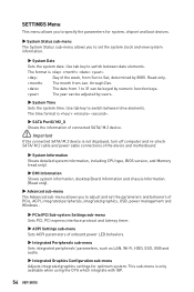
... M.2 cable and power cable connections of the device and motherboard. ▶▶System Information Shows detailed system information, including CPU type, BIOS version, and Memory (read only). ▶▶DMI Information Shows system information, desktop Board Information and chassis Information. (Read only)....System Date Sets the system date. The month from Sun to switch between date elements. Use tab key to Sat, determined by BIOS. Day of onboard power LED behaviors. ▶▶Integrated Peripherals sub-menu Sets integrated peripherals' parameters, such as LAN, Wi-...
... M.2 cable and power cable connections of the device and motherboard. ▶▶System Information Shows detailed system information, including CPU type, BIOS version, and Memory (read only). ▶▶DMI Information Shows system information, desktop Board Information and chassis Information. (Read only)....System Date Sets the system date. The month from Sun to switch between date elements. Use tab key to Sat, determined by BIOS. Day of onboard power LED behaviors. ▶▶Integrated Peripherals sub-menu Sets integrated peripherals' parameters, such as LAN, Wi-...
User Manual
Page 55
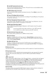
...boot states and the sequence of ErP and AC Power Loss behaviors. This function is disabled, you to load the BIOS default values or factory default settings into the BIOS and exit the BIOS setup utility with NVMe 1.3 compatible (and above) SSD devices. ▶▶Boot sub-menu Use this menu to... with or without authorization. ▶▶Save & Exit This menu allows you can optimize the system power consumption in this menu. ▶▶BIOS UEFI/CSM Mode [UEFI] Select CSM (Compatibility Support Module) or UEFI mode to effectively wipe all data from CMOS memory. UEFI...
...boot states and the sequence of ErP and AC Power Loss behaviors. This function is disabled, you to load the BIOS default values or factory default settings into the BIOS and exit the BIOS setup utility with NVMe 1.3 compatible (and above) SSD devices. ▶▶Boot sub-menu Use this menu to... with or without authorization. ▶▶Save & Exit This menu allows you can optimize the system power consumption in this menu. ▶▶BIOS UEFI/CSM Mode [UEFI] Select CSM (Compatibility Support Module) or UEFI mode to effectively wipe all data from CMOS memory. UEFI...
User Manual
Page 56
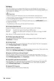
... is only recommended for advanced users. ∙∙Overclocking is used to determine CPU clock speed. Note: We use GAME BOOST function for easy overclocking. ∙∙The BIOS items in OC menu will vary with the processor. ▶▶OC Explore Mode [Normal] Enables or disables to ...show the normal or expert version of OC settings. [Normal] Provides the regular OC settings in BIOS setup. [Expert] Provides the advanced OC settings for OC expert to configure in CPU core number. These items only appear when CPU Ratio Apply...
... is only recommended for advanced users. ∙∙Overclocking is used to determine CPU clock speed. Note: We use GAME BOOST function for easy overclocking. ∙∙The BIOS items in OC menu will vary with the processor. ▶▶OC Explore Mode [Normal] Enables or disables to ...show the normal or expert version of OC settings. [Normal] Provides the regular OC settings in BIOS setup. [Expert] Provides the advanced OC settings for OC expert to configure in CPU core number. These items only appear when CPU Ratio Apply...


