
User Guide
Page 8
... Technical Support ...ii Safety Instructions ...iii FCC-B Radio Frequency Interference Statement iv W EEE (Waste Electrical and Electronic Equipment) Statement v Chapter 1. Hardware Setup 2-1 Quick Components Guide 2-2 CPU (Central Processing Unit 2-3 Memory ...2-7 Power Supply ...2-8 Back Panel ...2-9 Connectors ...2-11 Jumpers ...2-18 Slots ...2-19 Chapter 3 BIOS Setup 3-1 Entering Setup ...3-2 The Main Menu ...3-4 Standard CMOS Features...
... Technical Support ...ii Safety Instructions ...iii FCC-B Radio Frequency Interference Statement iv W EEE (Waste Electrical and Electronic Equipment) Statement v Chapter 1. Hardware Setup 2-1 Quick Components Guide 2-2 CPU (Central Processing Unit 2-3 Memory ...2-7 Power Supply ...2-8 Back Panel ...2-9 Connectors ...2-11 Jumpers ...2-18 Slots ...2-19 Chapter 3 BIOS Setup 3-1 Entering Setup ...3-2 The Main Menu ...3-4 Standard CMOS Features...

User Guide
Page 12
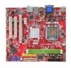
... Support - Supports Intel® Core 2 Quad, Core 2 Duo, Pentium, Celeron processors in the LGA775 package. (For the latest information about CPU, please visit http://www.msi.com.tw/cpusupport.htm) Supported FSB - DDR2 533/667/800 SDRAM (240pin/ non-ECC) (for 73U/PV) - SATA1~4 support RAID 0,...integrated by Realtek® RTL 8201CL (for 73V) - 2 DDR2 DIMMs (4GB Max) (For more information on compatible components, please visit http://www.msi.com.tw/testreport.htm) LAN - Supports Ultra DMA 66/100/133, PIO & Bus Master operation mode SATA - 4 SATAII ports support 4 SATA devices...
... Support - Supports Intel® Core 2 Quad, Core 2 Duo, Pentium, Celeron processors in the LGA775 package. (For the latest information about CPU, please visit http://www.msi.com.tw/cpusupport.htm) Supported FSB - DDR2 533/667/800 SDRAM (240pin/ non-ECC) (for 73U/PV) - SATA1~4 support RAID 0,...integrated by Realtek® RTL 8201CL (for 73V) - 2 DDR2 DIMMs (4GB Max) (For more information on compatible components, please visit http://www.msi.com.tw/testreport.htm) LAN - Supports Ultra DMA 66/100/133, PIO & Bus Master operation mode SATA - 4 SATAII ports support 4 SATA devices...
User Guide
Page 16
Also, it provides the instructions on connecting the peripheral devices, such as how to install the CPU, memory modules, and expansion cards, as well as the mouse, keyboard, etc. Chapter 2 Hardware Setup This chapter tells you how to setup the jumpers on the mainboard. W hile doing the installation, be careful in holding the components and follow the installation procedures.
Also, it provides the instructions on connecting the peripheral devices, such as how to install the CPU, memory modules, and expansion cards, as well as the mouse, keyboard, etc. Chapter 2 Hardware Setup This chapter tells you how to setup the jumpers on the mainboard. W hile doing the installation, be careful in holding the components and follow the installation procedures.

User Guide
Page 18
...to LGA 775 CPU The pin-pad side of CPU. Hardware Setup CPU (Central Processing ... Replaceing the CPU While replacing the CPU, always turn off the ATX power supply... or unplug the power supply's power cord from overheating. Remember to enhance heat dissipation. The surface of thermal paste (or thermal tape) between the CPU and the heatsink to apply some thermal paste on the computer. When you apply an even layer of LGA 775 CPU.... We do not have the CPU cooler, consult your components are installing the CPU...CPU from the grounded outlet first to ...
...to LGA 775 CPU The pin-pad side of CPU. Hardware Setup CPU (Central Processing ... Replaceing the CPU While replacing the CPU, always turn off the ATX power supply... or unplug the power supply's power cord from overheating. Remember to enhance heat dissipation. The surface of thermal paste (or thermal tape) between the CPU and the heatsink to apply some thermal paste on the computer. When you apply an even layer of LGA 775 CPU.... We do not have the CPU cooler, consult your components are installing the CPU...CPU from the grounded outlet first to ...

User Guide
Page 19
...hinge side (as the arrow shows). 3. The availability of the CPU land side cover depends on your CPU & mainboard. 1. Do not touch the CPU socket pins to prevent overheating. Before you are installing the CPU, make sure the CPU has a cooler attached on the top to avoid damaging. 3. ...Open the load lever. MS-7366 Mainboard CPU & Cooler Installation W hen you install the CPU, always cover it to protect the socket pin. 2. Follow the steps below to apply some thermal paste on CPU before turning on your CPU cooler is firmly installed before installing the heat ...
...hinge side (as the arrow shows). 3. The availability of the CPU land side cover depends on your CPU & mainboard. 1. Do not touch the CPU socket pins to prevent overheating. Before you are installing the CPU, make sure the CPU has a cooler attached on the top to avoid damaging. 3. ...Open the load lever. MS-7366 Mainboard CPU & Cooler Installation W hen you install the CPU, always cover it to protect the socket pin. 2. Follow the steps below to apply some thermal paste on CPU before turning on your CPU cooler is firmly installed before installing the heat ...
User Guide
Page 20
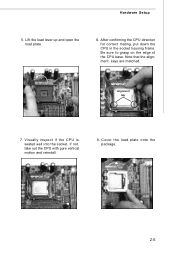
After confirming the CPU direction for correct mating, put down the CPU in the socket housing frame. Be sure to grasp on the edge of the CPU base. alignment key 7. Visually inspect if the CPU is seated well into the socket. If not, take out the CPU with pure vertical motion and reinstall. 8. Note that the alignment keys are matched. Hardware Setup 5. Cover the load plate onto the p ac k age. 2-5 Lift the load lever up and open the load plate. 6.
After confirming the CPU direction for correct mating, put down the CPU in the socket housing frame. Be sure to grasp on the edge of the CPU base. alignment key 7. Visually inspect if the CPU is seated well into the socket. If not, take out the CPU with pure vertical motion and reinstall. 8. Note that the alignment keys are matched. Hardware Setup 5. Cover the load plate onto the p ac k age. 2-5 Lift the load lever up and open the load plate. 6.
User Guide
Page 21
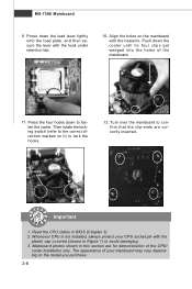
... lever lightly onto the load plate, and then secure the lever with the hook under retention tab. 10. Read the CPU status in Figure 1) to lock the h ook s . 12. Whenever CPU is not installed, always protect your mainboard may vary depending on the model you purchase. 2-6 Then rotate the locking switch... (refer to confirm that the clip-ends are for demonstration of the mainboard. 11. The appearance of your CPU socket pin with the heatsink. Push down the cooler until its four clips get wedged into the holes of the...
... lever lightly onto the load plate, and then secure the lever with the hook under retention tab. 10. Read the CPU status in Figure 1) to lock the h ook s . 12. Whenever CPU is not installed, always protect your mainboard may vary depending on the model you purchase. 2-6 Then rotate the locking switch... (refer to confirm that the clip-ends are for demonstration of the mainboard. 11. The appearance of your CPU socket pin with the heatsink. Push down the cooler until its four clips get wedged into the holes of the...
User Guide
Page 23
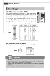
...use the 20-pin ATX power supply, please ...ATX 12V Power Connector: PWR1 This 12V power connector is highly recommended for system stability. 3. ATX 12V power connection should be greater than 18A. 2-8 To connect the ATX... 24-pin power supply, make sure the plug of the power supply is inserted in the proper orientation and the pins are connected to proper ATX... power supplies to ensure stable operation of 350 watts (and above) is used to provide power to connect an ATX... 24-pin power supply. Make sure that all the connectors are aligned. MS-7366 Mainboard Power Supply ATX...
...use the 20-pin ATX power supply, please ...ATX 12V Power Connector: PWR1 This 12V power connector is highly recommended for system stability. 3. ATX 12V power connection should be greater than 18A. 2-8 To connect the ATX... 24-pin power supply, make sure the plug of the power supply is inserted in the proper orientation and the pins are connected to proper ATX... power supplies to ensure stable operation of 350 watts (and above) is used to provide power to connect an ATX... 24-pin power supply. Make sure that all the connectors are aligned. MS-7366 Mainboard Power Supply ATX...
User Guide
Page 27
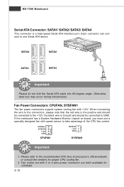
... 2V GND SYSFAN1 Important 1. Fan Power Connectors: CPUFAN, SYSFAN1 The fan power connectors support system cooling fan with speed sensor to the recommended CPU fans at processor's official website or consult the vendors for CPUFAN. 2-12 If the mainboard has a System Hardware Monitor chipset on-board, you... must use a specially designed fan with +12V. Fan cooler set with 3 or 4 pins power connector are both available for proper CPU cooling fan. 2. the black wire is the positive and should be connected to one Serial ATA device. Each connector can connect to the +12V...
... 2V GND SYSFAN1 Important 1. Fan Power Connectors: CPUFAN, SYSFAN1 The fan power connectors support system cooling fan with speed sensor to the recommended CPU fans at processor's official website or consult the vendors for CPUFAN. 2-12 If the mainboard has a System Hardware Monitor chipset on-board, you... must use a specially designed fan with +12V. Fan cooler set with 3 or 4 pins power connector are both available for proper CPU cooling fan. 2. the black wire is the positive and should be connected to one Serial ATA device. Each connector can connect to the +12V...
User Guide
Page 43
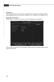
This sub-menu shows the CPU information, BIOS version and memory status of floppy drives installed. System Information Press to set the type of your system (read only). 3-8 Available options: [None], [360K, 5.25 in.], [1.2M, 5.25 in.], [720K, 3.5 in.], [1.44M, 3.5 in.], [2.88M, 3.5 in.]. MS-7366 Mainboard Floppy A This item allows you to enter the sub-menu, and the following screen appears.
This sub-menu shows the CPU information, BIOS version and memory status of floppy drives installed. System Information Press to set the type of your system (read only). 3-8 Available options: [None], [360K, 5.25 in.], [1.2M, 5.25 in.], [720K, 3.5 in.], [1.44M, 3.5 in.], [2.88M, 3.5 in.]. MS-7366 Mainboard Floppy A This item allows you to enter the sub-menu, and the following screen appears.

User Guide
Page 45
CPU Feature Press to enter the sub-menu: Execute Disable Bit Intel's Execute Disable Bit functionality can prevent certain classes of malicious "buffer overflow" attacks when ...
CPU Feature Press to enter the sub-menu: Execute Disable Bit Intel's Execute Disable Bit functionality can prevent certain classes of malicious "buffer overflow" attacks when ...
User Guide
Page 48
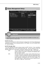
ACPI Function This item is lost (CPU or chipset) and hardware main- If your operating system supports ACPI, such as W indows 2000/ XP, select [Enabled]. Settings are available only when your operating ...
ACPI Function This item is lost (CPU or chipset) and hardware main- If your operating system supports ACPI, such as W indows 2000/ XP, select [Enabled]. Settings are available only when your operating ...
User Guide
Page 50
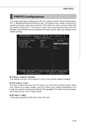
... Peripheral Component Interconnect, is a system which graphics card is strongly recommended that only experienced users should set to operate at speeds nearing the speed the CPU itself uses when communicating with its special components. BIOS Setup PNP/PCI Configurations This section describes configuring the PCI bus system and PnP (Plug & Play...
... Peripheral Component Interconnect, is a system which graphics card is strongly recommended that only experienced users should set to operate at speeds nearing the speed the CPU itself uses when communicating with its special components. BIOS Setup PNP/PCI Configurations This section describes configuring the PCI bus system and PnP (Plug & Play...
User Guide
Page 52
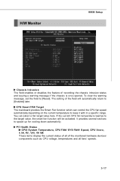
...message, set the field to speed up for cooling down automaticlly . The setting of the field will be activated. PC Health Status CPU/ System Temperature, CPU FAN/ SYS FAN1 Speed, CPU Vcore, 3.3V, 5V, 12V, 5V SB These items display the current status of all of recording the chassis intrusion status and... issuing a warning message if the chassis is once opened. It provides several sections to [Reset]. If the current CPU fan temperature reaches to the target value, the smart fan function will automatically return to keep it with in a specific range...
...message, set the field to speed up for cooling down automaticlly . The setting of the field will be activated. PC Health Status CPU/ System Temperature, CPU FAN/ SYS FAN1 Speed, CPU Vcore, 3.3V, 5V, 12V, 5V SB These items display the current status of all of recording the chassis intrusion status and... issuing a warning message if the chassis is once opened. It provides several sections to [Reset]. If the current CPU fan temperature reaches to the target value, the smart fan function will automatically return to keep it with in a specific range...

User Guide
Page 53
... The Enhanced Intel SpeedStep technology allows you set the performance level of the microprocessor whether the computer is running on battery or AC power. Current CPU/ FSB/ DRAM Frequency These items show the current clocks of the DRAM timing. Advance DRAM Configuration Press to enter the sub-menu: Memory Timings This... clock frequency (in MHz). This field will be selectable. 3-18 MS-7366 Mainboard Frequency/Voltage Control Important Change these settings only if you installed the CPU which support speedstep technology. System Clock Mode item allows you to automatically detect all of...
... The Enhanced Intel SpeedStep technology allows you set the performance level of the microprocessor whether the computer is running on battery or AC power. Current CPU/ FSB/ DRAM Frequency These items show the current clocks of the DRAM timing. Advance DRAM Configuration Press to enter the sub-menu: Memory Timings This... clock frequency (in MHz). This field will be selectable. 3-18 MS-7366 Mainboard Frequency/Voltage Control Important Change these settings only if you installed the CPU which support speedstep technology. System Clock Mode item allows you to automatically detect all of...
User Guide
Page 98
...-ROM drive for software installation. 4. Operation system: W indows XP. 5. Intel Pentium4 / Celeron, AMD Athlon XP/ Sempron or compatible CPU with PCI Express slot. 2. 256MB system memory. 3. Dual Core Center Appendix C Dual Core Center Dual CoreCenter, the most useful and powerful utility that... MSI has spent much research and efforts to develop, helps users to monitor or configure the hardware status of MSI Mainboard & MSI Graphics card in windows, such as CPU/GPU clock, voltage, fan speed and temperature. DotNet Frame Work...
...-ROM drive for software installation. 4. Operation system: W indows XP. 5. Intel Pentium4 / Celeron, AMD Athlon XP/ Sempron or compatible CPU with PCI Express slot. 2. 256MB system memory. 3. Dual Core Center Appendix C Dual Core Center Dual CoreCenter, the most useful and powerful utility that... MSI has spent much research and efforts to develop, helps users to monitor or configure the hardware status of MSI Mainboard & MSI Graphics card in windows, such as CPU/GPU clock, voltage, fan speed and temperature. DotNet Frame Work...

User Guide
Page 100
Dual Core Center Main Before using this utility. C-3 If you : only when installing the MSI V044 (V044 has to install with the version 8.26 or newer driver)/ V046 or V060 graphics card can activate the full function of this utility, ...we have to remind you install a graphics card of other brand, only hardware status of the MSI mainboard would be available. MB Click MB button to read current CPU temperature, FSB and CPU clock of graphics card will show below . DOT Click DOT button to execute the function. Introduction: Click each...
Dual Core Center Main Before using this utility. C-3 If you : only when installing the MSI V044 (V044 has to install with the version 8.26 or newer driver)/ V046 or V060 graphics card can activate the full function of this utility, ...we have to remind you install a graphics card of other brand, only hardware status of the MSI mainboard would be available. MB Click MB button to read current CPU temperature, FSB and CPU clock of graphics card will show below . DOT Click DOT button to execute the function. Introduction: Click each...

User Guide
Page 102
...regularly first. There will be powered only when users' PC runs huge amount of data, like 3D games or video process, and the motherboard/ graphicd card need to conduct overclocking manually, please do not to apply the DOT function. DOT FSB-UP Rate button DOT FSB-DOWN... make the system run smoother and faster. Dual Core Center DOT (Dynamic OverClocking) Dynamic Overclocking Technology is designed to detect the loading of CPU/ GPU while running programs, and to over-clock automatically. It is an automatic overclocking function, included in low loading balance, it is...
...regularly first. There will be powered only when users' PC runs huge amount of data, like 3D games or video process, and the motherboard/ graphicd card need to conduct overclocking manually, please do not to apply the DOT function. DOT FSB-UP Rate button DOT FSB-DOWN... make the system run smoother and faster. Dual Core Center DOT (Dynamic OverClocking) Dynamic Overclocking Technology is designed to detect the loading of CPU/ GPU while running programs, and to over-clock automatically. It is an automatic overclocking function, included in low loading balance, it is...

User Guide
Page 103
.... And you do not want to apply the adjustments, click the Cancel button to select for overclocking. If you can see clock status (including FSB/ CPU clock of mainboard and GPU/ memory clock of graphics card) of the item which the button is not available. Only the curves of your system.
.... And you do not want to apply the adjustments, click the Cancel button to select for overclocking. If you can see clock status (including FSB/ CPU clock of mainboard and GPU/ memory clock of graphics card) of the item which the button is not available. Only the curves of your system.
User Guide
Page 105
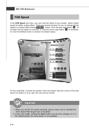
..., clicking the Save button can read fan status of the fan speed. Select higher speed for you to change the fan speed to disabled the "CPU Smart FAN Target" item in the BIOS. 2. Important 1. When you set the fan speed manually, please make sure to a section after clicking button. There are...
..., clicking the Save button can read fan status of the fan speed. Select higher speed for you to change the fan speed to disabled the "CPU Smart FAN Target" item in the BIOS. 2. Important 1. When you set the fan speed manually, please make sure to a section after clicking button. There are...

