
User Guide
Page 8
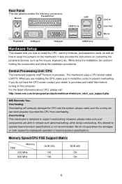
... • Supports two memory banks using two 184-pin DDR DIMM. • Supports up to 3.2GHz, and Intel P4 Prescott Celeron CPU. (For the latest information about CPU, please visit http://www.msi.com.tw/program/products/mainboard/mbd/pro_mbd_cpu_support.php ) Chipset • VIA® P4M800CE chipset - ACPI & PC2001 compliant enhanced power management...
... • Supports two memory banks using two 184-pin DDR DIMM. • Supports up to 3.2GHz, and Intel P4 Prescott Celeron CPU. (For the latest information about CPU, please visit http://www.msi.com.tw/program/products/mainboard/mbd/pro_mbd_cpu_support.php ) Chipset • VIA® P4M800CE chipset - ACPI & PC2001 compliant enhanced power management...
User Guide
Page 10
... guarantee the damages or risks caused by inadequate operation or beyond product specifications is designed to support overclocking. For the latest information about CPU, please visit http://www.msi.com.tw/program/products/mainboard/mbd/pro_mbd_cpu_support.php. However, please make sure your dealer to purchase and install them before turning on the...
... guarantee the damages or risks caused by inadequate operation or beyond product specifications is designed to support overclocking. For the latest information about CPU, please visit http://www.msi.com.tw/program/products/mainboard/mbd/pro_mbd_cpu_support.php. However, please make sure your dealer to purchase and install them before turning on the...
User Guide
Page 11
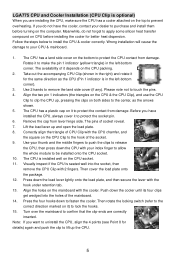
...load plate, and then secure the lever with the hook under retention tab. 13. Note: If you want to lift up the CPU. 5 Meanwhile, do not have installed the CPU, always cover it for the same direction as the arrows shown. 5. Press down the cooler until its four clips get wedged ... and open the load plate. 8. The pins of the mainboard. 14. Align the two pin 1 indicators (the triangles on the CPU & the CPU Clip), and use the CPU Clip to protect the socket pin. 6. Lift the load lever up , pressing the clips on the mainboard with 2 fingers. Wrong installation will cause the...
...load plate, and then secure the lever with the hook under retention tab. 13. Note: If you want to lift up the CPU. 5 Meanwhile, do not have installed the CPU, always cover it for the same direction as the arrows shown. 5. Press down the cooler until its four clips get wedged ... and open the load plate. 8. The pins of the mainboard. 14. Align the two pin 1 indicators (the triangles on the CPU & the CPU Clip), and use the CPU Clip to protect the socket pin. 6. Lift the load lever up , pressing the clips on the mainboard with 2 fingers. Wrong installation will cause the...
User Guide
Page 12
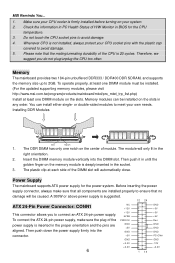
... pins with the plastic cap covered to connect an ATX 24-pin power supply. Do not touch the CPU socket pins to meet your system. 2. Installing DDR Modules Volt Notch 1. MSI Reminds You... 1. Therefore, we suggest you to avoid damage. 5. Memory modules can install either ... damage. 4. Check the information in PC Health Status of H/W Monitor in the right orientation. 2. Power Supply The mainboard supports ATX power supply for the CPU temperature. 3. The module will only fit in BIOS for the power system. Insert the DIMM memory module vertically into the connector...
... pins with the plastic cap covered to connect an ATX 24-pin power supply. Do not touch the CPU socket pins to meet your system. 2. Installing DDR Modules Volt Notch 1. MSI Reminds You... 1. Therefore, we suggest you to avoid damage. 5. Memory modules can install either ... damage. 4. Check the information in PC Health Status of H/W Monitor in the right orientation. 2. Power Supply The mainboard supports ATX power supply for the CPU temperature. 3. The module will only fit in BIOS for the power system. Insert the DIMM memory module vertically into the connector...

User Guide
Page 13
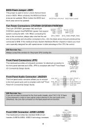
IDE1 can connect up to use the 20-pin ATX power supply as you 'd like . MSI Reminds You... The ports supper 1st generation Serial ATA data rates of data during transmission. MSI Reminds You... GND R Chassis Intrusion Switch Connector: JC1 This connector is connected to IDE1. If you like to ...angle, which will cause the loss of 150MB/s and are fully compliant with pin 1 & pin 13. Each Serial ATA connector can connect to the CPU. 12V Floppy Disk Drive Connector: FDD1 The mainboard provides a standard floppy disk drive connector that supports 360K, 720K, 1.2M, 1.44M and 2.88M ...
IDE1 can connect up to use the 20-pin ATX power supply as you 'd like . MSI Reminds You... The ports supper 1st generation Serial ATA data rates of data during transmission. MSI Reminds You... GND R Chassis Intrusion Switch Connector: JC1 This connector is connected to IDE1. If you like to ...angle, which will cause the loss of 150MB/s and are fully compliant with pin 1 & pin 13. Each Serial ATA connector can connect to the CPU. 12V Floppy Disk Drive Connector: FDD1 The mainboard provides a standard floppy disk drive connector that supports 360K, 720K, 1.2M, 1.44M and 2.88M ...
User Guide
Page 14
...PWRFAN1 The 4-pin CPUFAN1 (processor fan) and 3-pin SYSFAN1 (system fan)/PWRFAN1 (power fan) support system cooling fan with +12V. MSI Reminds You... JFP2 is Ground and should be connected to lock or unlock the boot block area on BIOS. AUD_RET_L Key AUD_RET_R AUD_VCC ...USB2.0 technology increases 8 (9)Key (10)USB0C USB0+ GND USB0- Front Panel Connectors: JFP2 The mainboard provides a front panel connector for the proper CPU cooling fan. VCC(1) VCC(2) GND USB1USB1+ If the mainboard has a System Hardware Monitor chipset on the back panel will not function. 21 Front USB...
...PWRFAN1 The 4-pin CPUFAN1 (processor fan) and 3-pin SYSFAN1 (system fan)/PWRFAN1 (power fan) support system cooling fan with +12V. MSI Reminds You... JFP2 is Ground and should be connected to lock or unlock the boot block area on BIOS. AUD_RET_L Key AUD_RET_R AUD_VCC ...USB2.0 technology increases 8 (9)Key (10)USB0C USB0+ GND USB0- Front Panel Connectors: JFP2 The mainboard provides a front panel connector for the proper CPU cooling fan. VCC(1) VCC(2) GND USB1USB1+ If the mainboard has a System Hardware Monitor chipset on the back panel will not function. 21 Front USB...

User Guide
Page 17
... to load factory default settings into the BIOS for stable system performance operations. Exit Without Saving Abandon all changes and exit setup. Adjust CPU Ratio This item allows you are plagued by modulating the pulses so that the spikes of the pulses are overclocking because even a slight ...to [Enabled], the system will remove (turn off) clocks from [8] to adjust the CPU ratio. Auto Detect DIMM/PCI Clock This item is from empty DIMM and PCI slots to flatter curves. Spread Spectrum When the motherboard's clock generator pulses, the extreme values (spikes) of . But if you to [50...
... to load factory default settings into the BIOS for stable system performance operations. Exit Without Saving Abandon all changes and exit setup. Adjust CPU Ratio This item allows you are plagued by modulating the pulses so that the spikes of the pulses are overclocking because even a slight ...to [Enabled], the system will remove (turn off) clocks from [8] to adjust the CPU ratio. Auto Detect DIMM/PCI Clock This item is from empty DIMM and PCI slots to flatter curves. Spread Spectrum When the motherboard's clock generator pulses, the extreme values (spikes) of . But if you to [50...

User Guide
Page 18
...values provided by adjusting the FSB clock to a higher frequency. AGP Voltage AGP voltage is adjustable in the field, allowing you to select the CPU/AGP/PCI Front Side Bus clock frequency (in MHz) and overclock the processor by the mainboard manufacturer for long-term purpose is NOT recommended.... Adjust CPU/AGP/PCI Frequency This item allows you to increase the performance of your AGP display card when overclocking, but the stability may cause a ...
...values provided by adjusting the FSB clock to a higher frequency. AGP Voltage AGP voltage is adjustable in the field, allowing you to select the CPU/AGP/PCI Front Side Bus clock frequency (in MHz) and overclock the processor by the mainboard manufacturer for long-term purpose is NOT recommended.... Adjust CPU/AGP/PCI Frequency This item allows you to increase the performance of your AGP display card when overclocking, but the stability may cause a ...
User Guide
Page 64
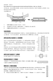
... PWR OK GND +5V GND +5V GND +3.3V +3.3V 1 13 GND +5V +5V +5V Res GND GND GND PS-ON# GND -12V +3.3V ATX 12V JPW1 12V 此 12V CPU 供电。 12V FDD1 1 FDD1,支持 360K, 720K, 1.2M, 1.44M 和 2.88M 42 31 GND GND IDE 接口... DMA 66/100/133 4 CD-ROM、120MB IDE1 接口。IDE1 1 个 Master 1 个 Slave 58 DDR DIMM 2. 将 DDR DDR 3. http://www.msi.com.tw/program/products/mainboard/mbd/pro_mbd_trp_list.php DDR 内存 Volt Notch 1.
... PWR OK GND +5V GND +5V GND +3.3V +3.3V 1 13 GND +5V +5V +5V Res GND GND GND PS-ON# GND -12V +3.3V ATX 12V JPW1 12V 此 12V CPU 供电。 12V FDD1 1 FDD1,支持 360K, 720K, 1.2M, 1.44M 和 2.88M 42 31 GND GND IDE 接口... DMA 66/100/133 4 CD-ROM、120MB IDE1 接口。IDE1 1 个 Master 1 个 Slave 58 DDR DIMM 2. 将 DDR DDR 3. http://www.msi.com.tw/program/products/mainboard/mbd/pro_mbd_trp_list.php DDR 内存 Volt Notch 1.
User Guide
Page 65
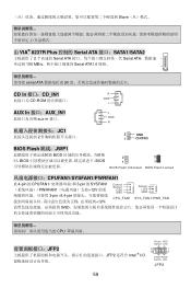
... 的 CPUFAN1 3-pin 的 SYSFAN1 PWRFAN1 12V 3-pin 或 4-pin 12V, Control Sensor +12V GND CPU_FAN1 Sensor +12V GND SY S _ FAN 1/ PWR _FAN GND CPU JFP2 JFP2 是符合 Intel ® I/O Reset HDD Switch LED 9 1 10 2 PowerPower Switch LED JFP2 59
... 的 CPUFAN1 3-pin 的 SYSFAN1 PWRFAN1 12V 3-pin 或 4-pin 12V, Control Sensor +12V GND CPU_FAN1 Sensor +12V GND SY S _ FAN 1/ PWR _FAN GND CPU JFP2 JFP2 是符合 Intel ® I/O Reset HDD Switch LED 9 1 10 2 PowerPower Switch LED JFP2 59
User Guide
Page 76
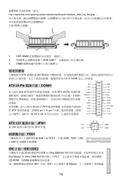
http://www.msi.com.tw/program/products/mainboard/mbd/pro_mbd_trp_list.php DDR 記憶體 Volt Notch 1. DDR DIMM 2. 將 DDR DDR 3. DIMM ATX 300W 12 24 ATX 24-Pin CONN1 ATX 24-Pin ATX 24-Pin 20-pin 的 ATX 20-pin 的 ATX pin 1 和 pin 13 pin 11, 12, 23 和 24... GND +5V GND +5V GND +3.3V +3.3V GND +5V +5V +5V Res GND GND GND PS-ON# GND -12V +3.3V 1 13 ATX 12V JPW1 12V 此 12V CPU 供電。 12V FDD1 1 FDD1,支援 360K, 720K, 1.2M, 1.44M 和 2.88M 42 31 GND GND IDE &#...
http://www.msi.com.tw/program/products/mainboard/mbd/pro_mbd_trp_list.php DDR 記憶體 Volt Notch 1. DDR DIMM 2. 將 DDR DDR 3. DIMM ATX 300W 12 24 ATX 24-Pin CONN1 ATX 24-Pin ATX 24-Pin 20-pin 的 ATX 20-pin 的 ATX pin 1 和 pin 13 pin 11, 12, 23 和 24... GND +5V GND +5V GND +3.3V +3.3V GND +5V +5V +5V Res GND GND GND PS-ON# GND -12V +3.3V 1 13 ATX 12V JPW1 12V 此 12V CPU 供電。 12V FDD1 1 FDD1,支援 360K, 720K, 1.2M, 1.44M 和 2.88M 42 31 GND GND IDE &#...
User Guide
Page 77
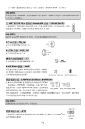
... 的 CPUFAN1 3-pin 的 SYSFAN1 PWRFAN1 12V 3-pin 或 4-pin 12V, Control Sensor +12V GND CPU_FAN1 Sensor +12V GND SY S _ FAN 1/ PWR _FAN GND CPU JFP2 JFP2 是符合 Intel ® I/O Reset HDD Switch LED 9 1 10 2 PowerPower Switch LED JFP2 71
... 的 CPUFAN1 3-pin 的 SYSFAN1 PWRFAN1 12V 3-pin 或 4-pin 12V, Control Sensor +12V GND CPU_FAN1 Sensor +12V GND SY S _ FAN 1/ PWR _FAN GND CPU JFP2 JFP2 是符合 Intel ® I/O Reset HDD Switch LED 9 1 10 2 PowerPower Switch LED JFP2 71
User Guide
Page 88
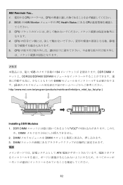
BIOS の H/W Monitor PC Health Status にある CPU 3. DIMM DIMM 3. DIMM ATX 82 MSI Reminds You... 1 CPU CPU 2. DDR DIMM VOLT め、DIMM 1 2. CPU 20 1GB 184 2 DDR DIMM DDR333/DDR400 SDRAM 1 つの DIMM http://www.msi.com.tw/program/products/mainboard/mbd/pro_mbd_trp_list.php ) Volt Notch Installing DDR Modules 1. CPU 5. CPU 4.
BIOS の H/W Monitor PC Health Status にある CPU 3. DIMM DIMM 3. DIMM ATX 82 MSI Reminds You... 1 CPU CPU 2. DDR DIMM VOLT め、DIMM 1 2. CPU 20 1GB 184 2 DDR DIMM DDR333/DDR400 SDRAM 1 つの DIMM http://www.msi.com.tw/program/products/mainboard/mbd/pro_mbd_trp_list.php ) Volt Notch Installing DDR Modules 1. CPU 5. CPU 4.

