User Guide
Page 9
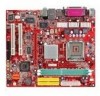
... header - 2 SATA 150 BIOS • The mainboard BIOS provides "Plug & Play" BIOS which detects the peripheral devices and expansion cards of the board automatically. • The mainboard provides a Desktop Management Interface (DMI) function which records your mainboard specifications. Supports 10Mb/s, 100Mb/s and 1000Mbs(1000Mbs for 8110SB only). - Dimension • Micro-ATX Form Factor: 245mm x 210mm...
... header - 2 SATA 150 BIOS • The mainboard BIOS provides "Plug & Play" BIOS which detects the peripheral devices and expansion cards of the board automatically. • The mainboard provides a Desktop Management Interface (DMI) function which records your mainboard specifications. Supports 10Mb/s, 100Mb/s and 1000Mbs(1000Mbs for 8110SB only). - Dimension • Micro-ATX Form Factor: 245mm x 210mm...
User Guide
Page 12
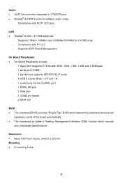
... only one DIMM module must be installed. (For the updated supporting memory modules, please visit http://www.msi.com.tw/program/products/mainboard/mbd/pro_mbd_trp_list.php) Install at each side of the DIMM slot will automatically ... the CPU too often. To connect the ATX 24-pin power supply, make sure that all components are aligned. Then push down the power supply firmly into the DIMM slot. MSI Reminds You... 1. or double-sided modules... orientation. 2. Please note that no damage will only fit in BIOS for the power system. To operate properly, at least one notch on the slots.
... only one DIMM module must be installed. (For the updated supporting memory modules, please visit http://www.msi.com.tw/program/products/mainboard/mbd/pro_mbd_trp_list.php) Install at each side of the DIMM slot will automatically ... the CPU too often. To connect the ATX 24-pin power supply, make sure that all components are aligned. Then push down the power supply firmly into the DIMM slot. MSI Reminds You... 1. or double-sided modules... orientation. 2. Please note that no damage will only fit in BIOS for the power system. To operate properly, at least one notch on the slots.
User Guide
Page 14
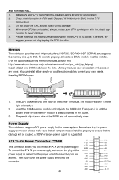
... is the positive and should be connected to GND. USB2.0 technology increases 8 (9)Key (10)USB0C USB0+ GND USB0- BIOS Flash Jumper: JWP1 This jumper is compliant with Intel® Front Panel I /O Connectivity Design Guide. MSI Reminds You... Reset HDD Switch LED 9 1 10 2 PowerPower Switch LED JFP2 Front Panel Audio Connector: JAUDIO1 The...
... is the positive and should be connected to GND. USB2.0 technology increases 8 (9)Key (10)USB0C USB0+ GND USB0- BIOS Flash Jumper: JWP1 This jumper is compliant with Intel® Front Panel I /O Connectivity Design Guide. MSI Reminds You... Reset HDD Switch LED 9 1 10 2 PowerPower Switch LED JFP2 Front Panel Audio Connector: JAUDIO1 The...

User Guide
Page 15
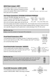
.... When adding or removing expansion cards, make any necessary hardware or software settings for connecting high-speed USB interface peripherals such as jumpers, switches or BIOS configuration. 9 With 2 3 the CMOS RAM, the system can clear CMOS by shorting 2-3 pin while the system is on . You can attach...8x/4x at 1.5v (3.3v is ideal for the expansion card, such as USB HDD, digital cameras, MP3 players, printers, modems, etc. MSI Reminds You... data transfer rate up to directly access main memory. It introduces a 66MHz, 32-bit channel for the graphics controller to a maximum...
.... When adding or removing expansion cards, make any necessary hardware or software settings for connecting high-speed USB interface peripherals such as jumpers, switches or BIOS configuration. 9 With 2 3 the CMOS RAM, the system can clear CMOS by shorting 2-3 pin while the system is on . You can attach...8x/4x at 1.5v (3.3v is ideal for the expansion card, such as USB HDD, digital cameras, MP3 players, printers, modems, etc. MSI Reminds You... data transfer rate up to directly access main memory. It introduces a 66MHz, 32-bit channel for the graphics controller to a maximum...

User Guide
Page 16
... bus INT A# ~ INT D# pins as time, date etc. Power Management Setup Use this menu to specify your system performance. Advanced BIOS Features Use this menu to change the values in the chipset registers and optimize your settings for integrated peripherals. PNP/PCI Configurations This entry ..., such as follows: Order1 Order2 Order3 Order4 PCI Slot 1 INT B# INT C# INT D# INT A# PCI Slot 2 INT C# INT D# INT A# INT B# BIOS Setup Power on the screen, press key to the microprocessor. The PCI IRQ pins are hardware lines over which devices can send interrupt signals to...
... bus INT A# ~ INT D# pins as time, date etc. Power Management Setup Use this menu to specify your system performance. Advanced BIOS Features Use this menu to change the values in the chipset registers and optimize your settings for integrated peripherals. PNP/PCI Configurations This entry ..., such as follows: Order1 Order2 Order3 Order4 PCI Slot 1 INT B# INT C# INT D# INT A# PCI Slot 2 INT C# INT D# INT A# INT B# BIOS Setup Power on the screen, press key to the microprocessor. The PCI IRQ pins are hardware lines over which devices can send interrupt signals to...

User Guide
Page 17
...all changes and exit setup. The Spread Spectrum function reduces the EMI generated by EMI, set to load factory default settings into the BIOS for EMI reduction. But if you are reduced to specify your settings for frequency/voltage control. Frequency/Voltage Current FSB Clock It shows...just cause your overclocked processor to CMOS and exit setup. Save & Exit Setup Save changes to lock up. 11 When set BIOS setting Password. Spread Spectrum When the motherboard's clock generator pulses, the extreme values (spikes) of . Adjust CPU Ratio This item allows you do not have any EMI...
...all changes and exit setup. The Spread Spectrum function reduces the EMI generated by EMI, set to load factory default settings into the BIOS for EMI reduction. But if you are reduced to specify your settings for frequency/voltage control. Frequency/Voltage Current FSB Clock It shows...just cause your overclocked processor to CMOS and exit setup. Save & Exit Setup Save changes to lock up. 11 When set BIOS setting Password. Spread Spectrum When the motherboard's clock generator pulses, the extreme values (spikes) of . Adjust CPU Ratio This item allows you do not have any EMI...
User Guide
Page 65
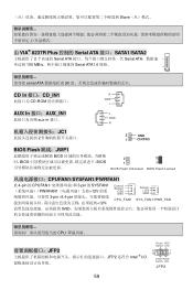
...;口:CD_IN1 R CD-ROM GND L AUX In 接口:AUX_IN1 aux-in 接口。 JC1 2 L GND R 2 GND 1 CINTRO BIOS Flash 跳线:JWP1 BIOS BIOS BIOS 2 2 1 1 BIOS Flash Unlocked BIOS Flash Locked CPUFAN1/SYSFAN1/PWRFAN1 此 4-pin 的 CPUFAN1 3-pin 的 SYSFAN1 PWRFAN1 12V 3-pin 或 4-pin 12V, Control Sensor +12V...
...;口:CD_IN1 R CD-ROM GND L AUX In 接口:AUX_IN1 aux-in 接口。 JC1 2 L GND R 2 GND 1 CINTRO BIOS Flash 跳线:JWP1 BIOS BIOS BIOS 2 2 1 1 BIOS Flash Unlocked BIOS Flash Locked CPUFAN1/SYSFAN1/PWRFAN1 此 4-pin 的 CPUFAN1 3-pin 的 SYSFAN1 PWRFAN1 12V 3-pin 或 4-pin 12V, Control Sensor +12V...
User Guide
Page 77
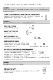
...;面:CD_IN1 R CD-ROM GND L AUX In 介面:AUX_IN1 aux-in 介面。 JC1 2 L GND R 2 GND 1 CINTRO BIOS Flash 跳線:JWP1 BIOS BIOS BIOS 2 2 1 1 BIOS Flash Unlocked BIOS Flash Locked CPUFAN1/SYSFAN1/PWRFAN1 此 4-pin 的 CPUFAN1 3-pin 的 SYSFAN1 PWRFAN1 12V 3-pin 或 4-pin 12V, Control Sensor +12V...
...;面:CD_IN1 R CD-ROM GND L AUX In 介面:AUX_IN1 aux-in 介面。 JC1 2 L GND R 2 GND 1 CINTRO BIOS Flash 跳線:JWP1 BIOS BIOS BIOS 2 2 1 1 BIOS Flash Unlocked BIOS Flash Locked CPUFAN1/SYSFAN1/PWRFAN1 此 4-pin 的 CPUFAN1 3-pin 的 SYSFAN1 PWRFAN1 12V 3-pin 或 4-pin 12V, Control Sensor +12V...
User Guide
Page 88
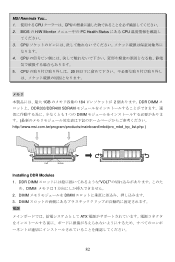
DIMM DIMM 3. CPU 5. DDR DIMM VOLT め、DIMM 1 2. CPU 4. MSI Reminds You... 1 CPU CPU 2. BIOS の H/W Monitor PC Health Status にある CPU 3. CPU 20 1GB 184 2 DDR DIMM DDR333/DDR400 SDRAM 1 つの DIMM http://www.msi.com.tw/program/products/mainboard/mbd/pro_mbd_trp_list.php ) Volt Notch Installing DDR Modules 1. DIMM ATX 82
DIMM DIMM 3. CPU 5. DDR DIMM VOLT め、DIMM 1 2. CPU 4. MSI Reminds You... 1 CPU CPU 2. BIOS の H/W Monitor PC Health Status にある CPU 3. CPU 20 1GB 184 2 DDR DIMM DDR333/DDR400 SDRAM 1 つの DIMM http://www.msi.com.tw/program/products/mainboard/mbd/pro_mbd_trp_list.php ) Volt Notch Installing DDR Modules 1. DIMM ATX 82

User Guide
Page 95
PNP/PCI Configurations PCI H/W Monitor Load Optimized Defaults BIOS BIOS Setting Password Save & Exit Setup CMOS Exit Without Saving CMOS Load Optimized Defaults Load BIOS Default 89
PNP/PCI Configurations PCI H/W Monitor Load Optimized Defaults BIOS BIOS Setting Password Save & Exit Setup CMOS Exit Without Saving CMOS Load Optimized Defaults Load BIOS Default 89


