User Manual
Page 13
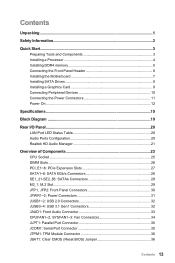
...: Front Audio Connector 33 CPUFAN1~2, SYSFAN1~3: Fan Connectors 34 JLPT1: Parallel Port Connector 35 JCOM1: Serial Port Connector 35 JTPM1: TPM Module Connector 36 JBAT1: Clear CMOS (Reset BIOS) Jumper 36 Contents 13
...: Front Audio Connector 33 CPUFAN1~2, SYSFAN1~3: Fan Connectors 34 JLPT1: Parallel Port Connector 35 JCOM1: Serial Port Connector 35 JTPM1: TPM Module Connector 36 JBAT1: Clear CMOS (Reset BIOS) Jumper 36 Contents 13

User Manual
Page 16
Continued from previous page USB ●● Intel® Z170 Chipset ▶▶8x USB 3.1 Gen1 (SuperSpeed USB) ports (4 ports on the back panel, 4 ports available through the internal USB 3.1 Gen 1 connectors) ▶▶6x ...; 1x TPM module connector ●● 1x Chassis Intrusion connector ●● 1x Serial port connector ●● 1x Parallel port connector ●● 1x Clear CMOS jumper NUVOTON NCT6793 Controller Chip Continued on next page 16 Specifications
Continued from previous page USB ●● Intel® Z170 Chipset ▶▶8x USB 3.1 Gen1 (SuperSpeed USB) ports (4 ports on the back panel, 4 ports available through the internal USB 3.1 Gen 1 connectors) ▶▶6x ...; 1x TPM module connector ●● 1x Chassis Intrusion connector ●● 1x Serial port connector ●● 1x Parallel port connector ●● 1x Clear CMOS jumper NUVOTON NCT6793 Controller Chip Continued on next page 16 Specifications
User Manual
Page 24
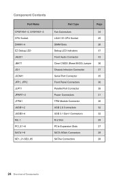
... PCI_E1~6 SATA1~6 SE1_21-SE2_65 Port Type Page Fan Connectors 34 LGA1151 CPU Socket 25 DIMM Slots 26 Debug LED indicators 37 Front Audio Connector 33 Clear CMOS (Reset BIOS) Jumper 36 Chassis Intrusion Connector 37 Serial Port Connector 35 Front Panel Connectors 30 Parallel Port Connector 35 Power Connectors 31 TPM Module...
... PCI_E1~6 SATA1~6 SE1_21-SE2_65 Port Type Page Fan Connectors 34 LGA1151 CPU Socket 25 DIMM Slots 26 Debug LED indicators 37 Front Audio Connector 33 Clear CMOS (Reset BIOS) Jumper 36 Chassis Intrusion Connector 37 Serial Port Connector 35 Front Panel Connectors 30 Parallel Port Connector 35 Power Connectors 31 TPM Module...
User Manual
Page 36
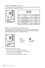
... off the computer and unplug the power cord 2. Use a jumper cap to short JBAT1 for TPM (Trusted Platform Module). Keep Data (default) Clear CMOS/ Reset BIOS Resetting BIOS to clear the CMOS memory. JTPM1: TPM Module Connector This connector is external powered from JBAT1. 4. Please refer to save system configuration data. If you want... address & data pin1 8 5V Power 9 LPC address & data pin2 10 No Pin 11 LPC address & data pin3 12 Ground 13 LPC Frame 14 Ground JBAT1: Clear CMOS (Reset BIOS) Jumper There is CMOS memory onboard that is for about 5-10 seconds. 3.
... off the computer and unplug the power cord 2. Use a jumper cap to short JBAT1 for TPM (Trusted Platform Module). Keep Data (default) Clear CMOS/ Reset BIOS Resetting BIOS to clear the CMOS memory. JTPM1: TPM Module Connector This connector is external powered from JBAT1. 4. Please refer to save system configuration data. If you want... address & data pin1 8 5V Power 9 LPC address & data pin2 10 No Pin 11 LPC address & data pin3 12 Ground 13 LPC Frame 14 Ground JBAT1: Clear CMOS (Reset BIOS) Jumper There is CMOS memory onboard that is for about 5-10 seconds. 3.

User Manual
Page 39
... F6 to load optimized defaults. ●● Short the Clear CMOS jumper on the motherboard. ●● Press the Clear CMOS button, on the rear I/O panel. (Only for resetting BIOS. Updating the BIOS with clear CMOS button.) Important Please refer to start updating BIOS. 6. Install and launch MSI LIVE UPDATE 6. 2. Updating BIOS Updating BIOS with M-FLASH Before...
... F6 to load optimized defaults. ●● Short the Clear CMOS jumper on the motherboard. ●● Press the Clear CMOS button, on the rear I/O panel. (Only for resetting BIOS. Updating the BIOS with clear CMOS button.) Important Please refer to start updating BIOS. 6. Install and launch MSI LIVE UPDATE 6. 2. Updating BIOS Updating BIOS with M-FLASH Before...
User Manual
Page 50
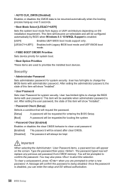
... [LEGACY+UEFI] Sets the system boot mode from CMOS memory. After setting the administrator password, the state of this item will be prompted to clear a set password. [Enabled] The password will be erased after clear CMOS. [Disabled] The password will be requested for system...will show "Installed". ▶▶User Password Sets User Password for booting the system. ▶▶Password Clear [Enabled] Enables or disables the clear CMOS behavior to confirm the password. Security ▶▶Administrator Password Sets administrator password for system boot. ▶▶...
... [LEGACY+UEFI] Sets the system boot mode from CMOS memory. After setting the administrator password, the state of this item will be prompted to clear a set password. [Enabled] The password will be erased after clear CMOS. [Disabled] The password will be requested for system...will show "Installed". ▶▶User Password Sets User Password for booting the system. ▶▶Password Clear [Enabled] Enables or disables the clear CMOS behavior to confirm the password. Security ▶▶Administrator Password Sets administrator password for system boot. ▶▶...

User Manual
Page 54
... user to memory. The system may become unstable or unbootable after changing memory timing. If it occurs, please clear the CMOS data and restore the default settings. (Refer to the Clear CMOS jumper/ button section to clear the CMOS data, and enter the BIOS to load the default settings.) ▶▶CPU Voltages control [Auto] These...
... user to memory. The system may become unstable or unbootable after changing memory timing. If it occurs, please clear the CMOS data and restore the default settings. (Refer to the Clear CMOS jumper/ button section to clear the CMOS data, and enter the BIOS to load the default settings.) ▶▶CPU Voltages control [Auto] These...

User Manual
Page 80
...USB audio devices. ●● Test with another known working graphics card. The computer does not boot after updating the BIOS ●● Clear the CMOS. ●● Use the secondary BIOS to audio ports on . ●● Check if the power switch cable is connected to JFP1 ...pin header properly. ●● Verify the Clear CMOS jumper JBAT1 is set to install only one memory module in the BIOS. Troubleshooting Before sending the motherboard for motherboard with Dual BIOS) 80 ...
...USB audio devices. ●● Test with another known working graphics card. The computer does not boot after updating the BIOS ●● Clear the CMOS. ●● Use the secondary BIOS to audio ports on . ●● Check if the power switch cable is connected to JFP1 ...pin header properly. ●● Verify the Clear CMOS jumper JBAT1 is set to install only one memory module in the BIOS. Troubleshooting Before sending the motherboard for motherboard with Dual BIOS) 80 ...


