User Manual
Page 13
... 33 CPUFAN1~2, SYSFAN1~3: Fan Connectors 34 JLPT1: Parallel Port Connector 35 JCOM1: Serial Port Connector 35 JTPM1: TPM Module Connector 36 JBAT1: Clear CMOS (Reset BIOS) Jumper 36 Contents 13
... 33 CPUFAN1~2, SYSFAN1~3: Fan Connectors 34 JLPT1: Parallel Port Connector 35 JCOM1: Serial Port Connector 35 JTPM1: TPM Module Connector 36 JBAT1: Clear CMOS (Reset BIOS) Jumper 36 Contents 13
User Manual
Page 14
JCI1: Chassis Intrusion Connector 37 EZ Debug LED: Debug LED indicators 37 BIOS Setup...38 Entering BIOS Setup 38 Resetting BIOS 39 Updating BIOS...39 EZ Mode...40 Advanced Mode 42 SETTINGS...43 Advanced...43 Boot...49 Security...50 Save & Exit...51 OC...52 M-FLASH...58 OC PROFILE...59 ...
JCI1: Chassis Intrusion Connector 37 EZ Debug LED: Debug LED indicators 37 BIOS Setup...38 Entering BIOS Setup 38 Resetting BIOS 39 Updating BIOS...39 EZ Mode...40 Advanced Mode 42 SETTINGS...43 Advanced...43 Boot...49 Security...50 Save & Exit...51 OC...52 M-FLASH...58 OC PROFILE...59 ...
User Manual
Page 17
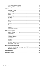
... Monitor Form Factor BIOS Features Software MSI Exclusive Features Continued ...from previous page ●● CPU/System temperature detection ●● CPU/System fan speed detection ●● CPU/System fan speed control ●● ATX Form Factor ●● 12 in . (30.5 cm x 22.5 cm) ●● 1x 128 Mb flash ●● UEFI AMI BIOS...Google Chrome™ ,Google Toolbar, Google Drive ●● CPU-Z ●● CLICK BIOS 5 ▶▶EZ Mode & Advanced Mode Switching ▶▶Board Explorer ▶▶...
... Monitor Form Factor BIOS Features Software MSI Exclusive Features Continued ...from previous page ●● CPU/System temperature detection ●● CPU/System fan speed detection ●● CPU/System fan speed control ●● ATX Form Factor ●● 12 in . (30.5 cm x 22.5 cm) ●● 1x 128 Mb flash ●● UEFI AMI BIOS...Google Chrome™ ,Google Toolbar, Google Drive ●● CPU-Z ●● CLICK BIOS 5 ▶▶EZ Mode & Advanced Mode Switching ▶▶Board Explorer ▶▶...
User Manual
Page 24
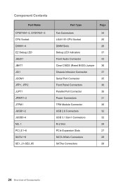
...-SE2_65 Port Type Page Fan Connectors 34 LGA1151 CPU Socket 25 DIMM Slots 26 Debug LED indicators 37 Front Audio Connector 33 Clear CMOS (Reset BIOS) Jumper 36 Chassis Intrusion Connector 37 Serial Port Connector 35 Front Panel Connectors 30 Parallel Port Connector 35 Power Connectors 31 TPM Module Connector 36...
...-SE2_65 Port Type Page Fan Connectors 34 LGA1151 CPU Socket 25 DIMM Slots 26 Debug LED indicators 37 Front Audio Connector 33 Clear CMOS (Reset BIOS) Jumper 36 Chassis Intrusion Connector 37 Serial Port Connector 35 Front Panel Connectors 30 Parallel Port Connector 35 Power Connectors 31 TPM Module Connector 36...
User Manual
Page 34
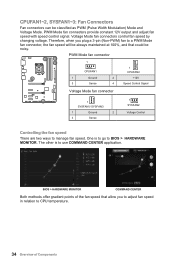
... speed that could be classified as PWM (Pulse Width Modulation) Mode and Voltage Mode. Voltage Mode fan connectors control fan speed by changing voltage. BIOS > HARDWARE MONITOR COMMAND CENTER Both methods offer gradient points of Components Therefore, when you plug a 3-pin (Non-PWM) fan to a PWM Mode...speed will be always maintained at 100%, and that allow you to adjust fan speed in relation to manage fan speed. One is to BIOS > HARDWARE MONITOR. CPUFAN1~2, SYSFAN1~3: Fan Connectors Fan connectors can be noisy. The other is to go to use COMMAND CENTER application. PWM...
... speed that could be classified as PWM (Pulse Width Modulation) Mode and Voltage Mode. Voltage Mode fan connectors control fan speed by changing voltage. BIOS > HARDWARE MONITOR COMMAND CENTER Both methods offer gradient points of Components Therefore, when you plug a 3-pin (Non-PWM) fan to a PWM Mode...speed will be always maintained at 100%, and that allow you to adjust fan speed in relation to manage fan speed. One is to BIOS > HARDWARE MONITOR. CPUFAN1~2, SYSFAN1~3: Fan Connectors Fan connectors can be noisy. The other is to go to use COMMAND CENTER application. PWM...
User Manual
Page 36
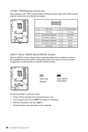
... 8 5V Power 9 LPC address & data pin2 10 No Pin 11 LPC address & data pin3 12 Ground 13 LPC Frame 14 Ground JBAT1: Clear CMOS (Reset BIOS) Jumper There is CMOS memory onboard that is for about 5-10 seconds. 3. If you want to clear the system configuration, set the jumpers to short... the computer and unplug the power cord 2. Plug the power cord and power on the motherboard to default values 1. Keep Data (default) Clear CMOS/ Reset BIOS Resetting BIOS to save system configuration data.
... 8 5V Power 9 LPC address & data pin2 10 No Pin 11 LPC address & data pin3 12 Ground 13 LPC Frame 14 Ground JBAT1: Clear CMOS (Reset BIOS) Jumper There is CMOS memory onboard that is for about 5-10 seconds. 3. If you want to clear the system configuration, set the jumpers to short... the computer and unplug the power cord 2. Plug the power cord and power on the motherboard to default values 1. Keep Data (default) Clear CMOS/ Reset BIOS Resetting BIOS to save system configuration data.

User Manual
Page 37
.... 2. indicates GPU is not detected or fail. Close the chassis cover. 3. Resetting the chassis intrusion warning 1. Connect the JCI1 connector to BIOS > Settings > Security > Chassis Intrusion Configuration. 2. VGA - Set Chassis Intrusion to Reset. 3. Set Chassis Intrusion to Enabled. 5. Press... F10 to save and exit and then press the Enter key to BIOS > Settings > Security > Chassis Intrusion Configuration. 4. JCI1: Chassis Intrusion Connector This connector allows you to select Yes. 6. CPU - indicates...
.... 2. indicates GPU is not detected or fail. Close the chassis cover. 3. Resetting the chassis intrusion warning 1. Connect the JCI1 connector to BIOS > Settings > Security > Chassis Intrusion Configuration. 2. VGA - Set Chassis Intrusion to Reset. 3. Set Chassis Intrusion to Enabled. 5. Press... F10 to save and exit and then press the Enter key to BIOS > Settings > Security > Chassis Intrusion Configuration. 4. JCI1: Chassis Intrusion Connector This connector allows you to select Yes. 6. CPU - indicates...
User Manual
Page 38
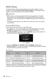
... GO2BIOS item (SETTING > Boot > GO2BIOS) in normal conditions. Click on the screen during the boot process. ●● Use MSI FAST BOOT application. Therefore, the description may vary from the latest BIOS and should always keep the default settings to enter Boot Menu message appears on GO2BIOS button and choose OK. Function...
... GO2BIOS item (SETTING > Boot > GO2BIOS) in normal conditions. Click on the screen during the boot process. ●● Use MSI FAST BOOT application. Therefore, the description may vary from the latest BIOS and should always keep the default settings to enter Boot Menu message appears on GO2BIOS button and choose OK. Function...

User Manual
Page 39
... CMOS button, on the rear I/O panel. (Only for resetting BIOS. And then save the BIOS file into the computer. 3. Press Del key to start updating BIOS. 6. Insert the USB flash drive that matches your motherboard model from MSI website. Select the M-FLASH tab and click on file. Install and... launch MSI LIVE UPDATE 6. 2. Check MB BIOS box and click on Scan button...
... CMOS button, on the rear I/O panel. (Only for resetting BIOS. And then save the BIOS file into the computer. 3. Press Del key to start updating BIOS. 6. Insert the USB flash drive that matches your motherboard model from MSI website. Select the M-FLASH tab and click on file. Install and... launch MSI LIVE UPDATE 6. 2. Check MB BIOS box and click on Scan button...
User Manual
Page 40
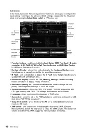
... setting. press this button to display the Hardware Monitor menu that provides the way to update BIOS with a USB flash drive. ●● Information display - profile. To configure the advanced BIOS settings, please enter the Advanced Mode by clicking on their respective button. ●● Hardware...CPU/ DDR speed, CPU/ MB temperature, MB/ CPU type, memory size, CPU/ DDR voltage, BIOS version and build date. ●● Language - click on left to select the language of BIOS setup. ●● Screenshot - press this button to display the M-Flash menu that allows you ...
... setting. press this button to display the Hardware Monitor menu that provides the way to update BIOS with a USB flash drive. ●● Information display - profile. To configure the advanced BIOS settings, please enter the Advanced Mode by clicking on their respective button. ●● Hardware...CPU/ DDR speed, CPU/ MB temperature, MB/ CPU type, memory size, CPU/ DDR voltage, BIOS version and build date. ●● Language - click on left to select the language of BIOS setup. ●● Screenshot - press this button to display the M-Flash menu that allows you ...
User Manual
Page 41
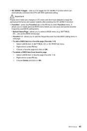
...from favorite page 1. press any changes in one page. ▶▶To add a BIOS item to enter Favorites menu. Right-click or press F2 key. 3. allows you can automatically overclock the CPU with MSI optimized setting. click on it to toggle the OC GENIE 4 function which can save... and access favorite/ frequently-used / favorite BIOS setting items in OC menu and don't load defaults to select a BIOS menu (e.g.
...from favorite page 1. press any changes in one page. ▶▶To add a BIOS item to enter Favorites menu. Right-click or press F2 key. 3. allows you can automatically overclock the CPU with MSI optimized setting. click on it to toggle the OC GENIE 4 function which can save... and access favorite/ frequently-used / favorite BIOS setting items in OC menu and don't load defaults to select a BIOS menu (e.g.
User Manual
Page 42
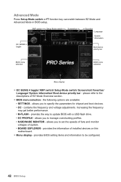
...9654;▶BOARD EXPLORER - please refer to specify the parameters for chipset and boot devices. ▶▶OC - provides BIOS setting items and information to update BIOS with a USB flash drive. ▶▶OC PROFILE - the following options are available: ▶▶SETTINGS - provides... selection - XMP switch Setup Mode switch Screenshot Favorites Language System information OC GENIE 4 toggle Boot device priority bar BIOS menu selection BIOS menu selection Menu display ●● OC GENIE 4 toggle/ XMP switch/ Setup Mode switch/ Screenshot/ Favorites/ Language/ ...
...9654;▶BOARD EXPLORER - please refer to specify the parameters for chipset and boot devices. ▶▶OC - provides BIOS setting items and information to update BIOS with a USB flash drive. ▶▶OC PROFILE - the following options are available: ▶▶SETTINGS - provides... selection - XMP switch Setup Mode switch Screenshot Favorites Language System information OC GENIE 4 toggle Boot device priority bar BIOS menu selection BIOS menu selection Menu display ●● OC GENIE 4 toggle/ XMP switch/ Setup Mode switch/ Screenshot/ Favorites/ Language/ ...
User Manual
Page 43
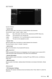
...time elements. SETTINGS System Status ▶▶System Date Sets the system date. Use tab key to 31 can be keyed by BIOS. through Dec. The time format is . Advanced ▶▶PCI Subsystem Settings Sets PCI, PCI express interface protocol and latency...;▶SATA PortX Shows the information of the device and motherboard. ▶▶System Information Shows detailed system information, including CPU type, BIOS version, and Memory (read only). ▶▶DMI Information Shows system information, desktop Board Information and chassis Information. (Read only)....
...time elements. SETTINGS System Status ▶▶System Date Sets the system date. Use tab key to 31 can be keyed by BIOS. through Dec. The time format is . Advanced ▶▶PCI Subsystem Settings Sets PCI, PCI express interface protocol and latency...;▶SATA PortX Shows the information of the device and motherboard. ▶▶System Information Shows detailed system information, including CPU type, BIOS version, and Memory (read only). ▶▶DMI Information Shows system information, desktop Board Information and chassis Information. (Read only)....
User Manual
Page 44
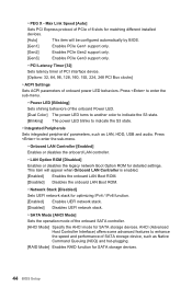
... mode of the onboard SATA controller. [AHCI Mode] Specify the AHCI mode for matching different installed devices. [Auto] This item will be configured automatically by BIOS. [Gen1] Enables PCIe Gen1 support only. [Gen2] Enables PCIe Gen2 support only. [Gen3] Enables PCIe Gen3 support only. ▶▶PCI Latency Timer [32] Sets... disables the onboard LAN controller. ▶▶LAN Option ROM [Disabled] Enables or disables the legacy network Boot Option ROM for SATA storage devices. 44 BIOS Setup ▶▶PEG X -
... mode of the onboard SATA controller. [AHCI Mode] Specify the AHCI mode for matching different installed devices. [Auto] This item will be configured automatically by BIOS. [Gen1] Enables PCIe Gen1 support only. [Gen2] Enables PCIe Gen2 support only. [Gen3] Enables PCIe Gen3 support only. ▶▶PCI Latency Timer [32] Sets... disables the onboard LAN controller. ▶▶LAN Option ROM [Disabled] Enables or disables the legacy network Boot Option ROM for SATA storage devices. 44 BIOS Setup ▶▶PEG X -

User Manual
Page 45
...-screen function for both integrated and external graphics cards. [Disabled] Disables this function. ▶▶USB Configuration Sets the onboard USB controller and device function. BIOS Setup 45 This item will appear when USB Controller is enabled. ▶▶Legacy USB Support [Enabled] Sets Legacy USB function support. [Auto] The system...
...-screen function for both integrated and external graphics cards. [Disabled] Disables this function. ▶▶USB Configuration Sets the onboard USB controller and device function. BIOS Setup 45 This item will appear when USB Controller is enabled. ▶▶Legacy USB Support [Enabled] Sets Legacy USB function support. [Auto] The system...
User Manual
Page 46
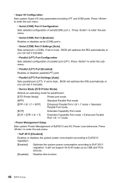
Press to Auto, BIOS will optimize the IRQ automatically or you can set it manually. ▶▶Parallel (LPT) Port Configuration Sets detailed configuration of parallel port (LPT). If ...-1.9/ 1.7 mode. ▶▶Power Management Setup Sets system Power Management of serial(COM) port x. Press to Auto, BIOS will not support S4 & S5 wake up by USB and PCIe devices. [Disabled] Disables this function. 46 BIOS Setup ▶▶Super IO Configuration Sets system Super I/O chip parameters including LPT and COM ports.
Press to Auto, BIOS will optimize the IRQ automatically or you can set it manually. ▶▶Parallel (LPT) Port Configuration Sets detailed configuration of parallel port (LPT). If ...-1.9/ 1.7 mode. ▶▶Power Management Setup Sets system Power Management of serial(COM) port x. Press to Auto, BIOS will not support S4 & S5 wake up by USB and PCIe devices. [Disabled] Disables this function. 46 BIOS Setup ▶▶Super IO Configuration Sets system Super I/O chip parameters including LPT and COM ports.
User Manual
Page 47
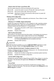
... will appear when Windows 8.1/ 10 WHQL Support is enabled, you can use MSI FAST BOOT application to enter BIOS setup if needed. This sub-menu will be available when MSI Fast Boot is enabled. Please refer Entering BIOS Setup section for details. ▶▶Fast Boot [Disabled/ windows7, Enabled/... the supports for Windows 8.1/ 10 or disables for Windows 8.1/ 10. BIOS Setup 47 It will switch to UEFI mode to meet the Windows requirement. [Disabled] Disables this function. ▶▶MSI Fast Boot [Disabled] MSI Fast Boot is faster than the boot time of Fast Boot. [Enabled...
... will appear when Windows 8.1/ 10 WHQL Support is enabled, you can use MSI FAST BOOT application to enter BIOS setup if needed. This sub-menu will be available when MSI Fast Boot is enabled. Please refer Entering BIOS Setup section for details. ▶▶Fast Boot [Disabled/ windows7, Enabled/... the supports for Windows 8.1/ 10 or disables for Windows 8.1/ 10. BIOS Setup 47 It will switch to UEFI mode to meet the Windows requirement. [Disabled] Disables this function. ▶▶MSI Fast Boot [Disabled] MSI Fast Boot is faster than the boot time of Fast Boot. [Enabled...
User Manual
Page 48
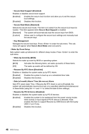
... RTC Alarm is set to [Enabled], the system will automatically resume (boot up) on a scheduled time/ date. [Disabled] Disables this function. 48 BIOS Setup This submenu will appear when Secure Boot Mode sets to enter the sub-menu. Press to enter the sub-menu. ▶▶Wake Up ...the power saving modes when activity or input signal of PCI-E device is enabled. [Standard] The system will automatically load the secure keys from BIOS. [Custom] Allows user to configure the secure boot settings and manually load the secure keys. ▶▶Key Management Manages the secure boot keys...
... RTC Alarm is set to [Enabled], the system will automatically resume (boot up) on a scheduled time/ date. [Disabled] Disables this function. 48 BIOS Setup This submenu will appear when Secure Boot Mode sets to enter the sub-menu. Press to enter the sub-menu. ▶▶Wake Up ...the power saving modes when activity or input signal of PCI-E device is enabled. [Standard] The system will automatically load the secure keys from BIOS. [Custom] Allows user to configure the secure boot settings and manually load the secure keys. ▶▶Key Management Manages the secure boot keys...

User Manual
Page 49
... in full screen. [Disabled] Shows the POST messages. ▶▶GO2BIOS [Disabled] Allows system to enter BIOS setup directly by pressing the Power button for 4 sec upon bootup. [Enabled] The system boots straight to the BIOS setup by long pressing the power button about 4 seconds when the system is detected. [Disabled] Disables...
... in full screen. [Disabled] Shows the POST messages. ▶▶GO2BIOS [Disabled] Allows system to enter BIOS setup directly by pressing the Power button for 4 sec upon bootup. [Enabled] The system boots straight to the BIOS setup by long pressing the power button about 4 seconds when the system is detected. [Disabled] Disables...
User Manual
Page 50
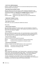
...selectable and will confirm the password is set password, press when you can enter the setup and OS without authorization. 50 BIOS Setup Security ▶▶Administrator Password Sets administrator password for booting the system. ▶▶Password Clear [Enabled] Enables ...". ▶▶Password Check [Setup] Selects a condition that will request the password. [Setup] A password will be requested for entering the BIOS Setup. [Boot] A password will show "Installed". ▶▶User Password Sets User Password for system boot. ▶▶Boot Option Priorities...
...selectable and will confirm the password is set password, press when you can enter the setup and OS without authorization. 50 BIOS Setup Security ▶▶Administrator Password Sets administrator password for booting the system. ▶▶Password Clear [Enabled] Enables ...". ▶▶Password Check [Setup] Selects a condition that will request the password. [Setup] A password will be requested for entering the BIOS Setup. [Boot] A password will show "Installed". ▶▶User Password Sets User Password for system boot. ▶▶Boot Option Priorities...


