

Owner's Manual Glossary
Page 17
... the preamp set at which contribute to -Z glossary. 17 XDR is generated in all variable controls to two inputs. Mackie mixers are so minuscule. See RMS. Z Z The electrical symbol for impedance. no loss either. VLZ is more susceptible to a minimum. unity gain A circuit or system that some bands have impedance. Unbalanced circuit connections...
... the preamp set at which contribute to -Z glossary. 17 XDR is generated in all variable controls to two inputs. Mackie mixers are so minuscule. See RMS. Z Z The electrical symbol for impedance. no loss either. VLZ is more susceptible to a minimum. unity gain A circuit or system that some bands have impedance. Unbalanced circuit connections...
Modifications
Page 3
...'BL' to 'AL' and 'BR' to 'AR' (channels 5-12). 6. Locate the 12 pins that comprise the underside of what screws go where. Place the mixer upside-down on a dry, non-marring surface. 3. Remove the screws that attach the bottom cover. Keep track of each MUTE/ALT 3-4 switch. 6. Be careful to... bottom cover back the way you found it . You're done! Be careful to cut all cords, including the power cable, from the 1202-VLZ PRO. 2. Place the mixer upside-down on a dry, non-marring surface. 3. Repeat for all channels. 8. Remove the bottom cover. 4. The work area is on the ...
...'BL' to 'AL' and 'BR' to 'AR' (channels 5-12). 6. Locate the 12 pins that comprise the underside of what screws go where. Place the mixer upside-down on a dry, non-marring surface. 3. Remove the screws that attach the bottom cover. Keep track of each MUTE/ALT 3-4 switch. 6. Be careful to... bottom cover back the way you found it . You're done! Be careful to cut all cords, including the power cable, from the 1202-VLZ PRO. 2. Place the mixer upside-down on a dry, non-marring surface. 3. Repeat for all channels. 8. Remove the bottom cover. 4. The work area is on the ...
Modifications
Page 5
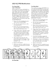
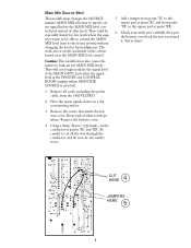
... of after (post). Remove all the way through the conductor, and do not cut any nearby traces. 5. Check your work area is selected). 1. Place the mixer upside-down on the underside of what screws go where. The work very carefully, then put the bottom cover back the way you found it... cover. Remove the bottom cover. 4. JUMPERS HERE CUT HERE 5 Add a jumper from point 'YL' to the square pad at point 'XL' and from the 1202-VLZ PRO. 2. You're done!
... of after (post). Remove all the way through the conductor, and do not cut any nearby traces. 5. Check your work area is selected). 1. Place the mixer upside-down on the underside of what screws go where. The work very carefully, then put the bottom cover back the way you found it... cover. Remove the bottom cover. 4. JUMPERS HERE CUT HERE 5 Add a jumper from point 'YL' to the square pad at point 'XL' and from the 1202-VLZ PRO. 2. You're done!
Modifications
Page 6
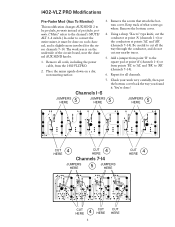
... be pre-fader, pre-mute instead of post-fader, postmute. ("Mute" refers to the channel's MUTE/ ALT 3-4 switch.) In order to convert the entire mixer, it . Keep track of the circuit board, near the channel AUX SEND knobs. 1. Repeat for the stereo channels 7-14. Channels 1-6 JUMPERS HERE 5 JUMPERS... where. Be careful to cut the conductor at point 'A' (channels 1-6) or the conductors at point 'A' (channels 1-6) or from the 1402-VLZ PRO. 2. 1402-VLZ PRO Modifications Pre-Fader Mod (Aux To Monitor) This modification changes AUX SEND 2 to be done on each channel, and is ...
... be pre-fader, pre-mute instead of post-fader, postmute. ("Mute" refers to the channel's MUTE/ ALT 3-4 switch.) In order to convert the entire mixer, it . Keep track of the circuit board, near the channel AUX SEND knobs. 1. Repeat for the stereo channels 7-14. Channels 1-6 JUMPERS HERE 5 JUMPERS... where. Be careful to cut the conductor at point 'A' (channels 1-6) or the conductors at point 'A' (channels 1-6) or from the 1402-VLZ PRO. 2. 1402-VLZ PRO Modifications Pre-Fader Mod (Aux To Monitor) This modification changes AUX SEND 2 to be done on each channel, and is ...
Modifications
Page 7
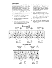
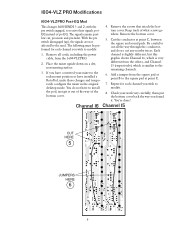
...MUTE/ALT 3-4 switches. 1. Using a sharp "X-acto" type knife, cut any nearby traces. 5. Repeat for the stereo channels 7-14. Be careful to convert the entire mixer, it . Channels 1-6 JUMPERS HERE 6 JUMPERS HERE 6 JUMPERS HERE 6 CUT 4 HERE CUT 4 HERE Channels 7-14 JUMPERS HERE 6 JUMPERS HERE CUT 4 HERE 6 ... of what screws go where. Check your work area is slightly more involved for all cords, including the power cable, from the 1402-VLZ PRO. 2. Remove all channels. 8. Keep track of each channel, and is on a dry, non-marring surface. 3. You're ...
...MUTE/ALT 3-4 switches. 1. Using a sharp "X-acto" type knife, cut any nearby traces. 5. Repeat for the stereo channels 7-14. Be careful to convert the entire mixer, it . Channels 1-6 JUMPERS HERE 6 JUMPERS HERE 6 JUMPERS HERE 6 CUT 4 HERE CUT 4 HERE Channels 7-14 JUMPERS HERE 6 JUMPERS HERE CUT 4 HERE 6 ... of what screws go where. Check your work area is slightly more involved for all cords, including the power cable, from the 1402-VLZ PRO. 2. Remove all channels. 8. Keep track of each channel, and is on a dry, non-marring surface. 3. You're ...
Modifications
Page 8
...to cut any nearby traces. 5. Add a jumper from point 'YL' to the square pad at points 'XL' and 'XR'. CUT HERE 4 JUMPERS HERE 5 8 Place the mixer upside-down on the underside of what screws go where. You're done! Using a sharp "X-acto" type knife, cut the conductor at point 'XR'. 6. They... will not longer indicate the signal level at the MAIN OUTS, but rather the signal level at point 'XL' and from the 1402-VLZ PRO. 2. Keep track of the circuit board, near the MAIN MIX level control. Remove the screws that attach the bottom cover. Remove all the way...
...to cut any nearby traces. 5. Add a jumper from point 'YL' to the square pad at points 'XL' and 'XR'. CUT HERE 4 JUMPERS HERE 5 8 Place the mixer upside-down on the underside of what screws go where. You're done! Using a sharp "X-acto" type knife, cut the conductor at point 'XR'. 6. They... will not longer indicate the signal level at the MAIN OUTS, but rather the signal level at point 'XL' and from the 1402-VLZ PRO. 2. Keep track of the circuit board, near the MAIN MIX level control. Remove the screws that attach the bottom cover. Remove all the way...
Modifications
Page 9
...C. 7. You're done! The following must be performed for each channel you have to modify: 1. Remove the bottom cover. 5. Check your mixer to cut all cords, including the power cable, from the others, and Channel 15 (respectively), which is similiar to receive their signals postEQ instead... JUMPERS HERE 6 9 Each channel is slightly different, but this graphic shows Channel 16, which is very different from the 1604-VLZ PRO. 2. 1604-VLZ PRO Modifications 1604-VLZ PRO Post-EQ Mod This changes AUX SENDS 1 and 2, with the pre switch engaged, to the remaining channels. 6. Remove the...
...C. 7. You're done! The following must be performed for each channel you have to modify: 1. Remove the bottom cover. 5. Check your mixer to cut all cords, including the power cable, from the others, and Channel 15 (respectively), which is similiar to receive their signals postEQ instead... JUMPERS HERE 6 9 Each channel is slightly different, but this graphic shows Channel 16, which is very different from the 1604-VLZ PRO. 2. 1604-VLZ PRO Modifications 1604-VLZ PRO Post-EQ Mod This changes AUX SENDS 1 and 2, with the pre switch engaged, to the remaining channels. 6. Remove the...
Modifications
Page 10
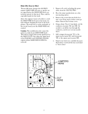
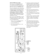
...jacks (you found them. Undo the PHONES nut. 3. Cut the conductor at point ZR. 9. Check your mixer to receive the main mix stereo signal pre-MAIN MIX fader instead of post-MAIN MIX fader. Remove all ...cords, including the power cable, from the square pad at point ZL and another from the 1604-VLZ PRO. 2. Add a jumper from the square pad at point YL to the square pad at point... can accomplish the same result that attach the bottom cover. Place the mixer upside-down on the board. 7. You're done! 1604-VLZ PRO Source Mod This changes the CTL ROOM/PHONES level control in the...
...jacks (you found them. Undo the PHONES nut. 3. Cut the conductor at point ZR. 9. Check your mixer to receive the main mix stereo signal pre-MAIN MIX fader instead of post-MAIN MIX fader. Remove all ...cords, including the power cable, from the square pad at point ZL and another from the 1604-VLZ PRO. 2. Add a jumper from the square pad at point YL to the square pad at point... can accomplish the same result that attach the bottom cover. Place the mixer upside-down on the board. 7. You're done! 1604-VLZ PRO Source Mod This changes the CTL ROOM/PHONES level control in the...

