Installation Instructions
Page 2
DRYER SAFETY 2
DRYER SAFETY 2

Installation Instructions
Page 3
... driver (recommended) Vent clamps Putty knife Level Parts supplied: Caulking gun and compound (for installing new exhaust vent) Leveling legs (4) Parts package is located in dryer drum. INSTALLATION REQUIREMENTS Tools and Parts Gather the required tools and parts before starting installation. Tools needed: Adjustable wrench that all parts are included. 3
... driver (recommended) Vent clamps Putty knife Level Parts supplied: Caulking gun and compound (for installing new exhaust vent) Leveling legs (4) Parts package is located in dryer drum. INSTALLATION REQUIREMENTS Tools and Parts Gather the required tools and parts before starting installation. Tools needed: Adjustable wrench that all parts are included. 3

Installation Instructions
Page 4
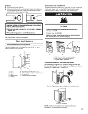
... (76 mm) 4 A B A. Wide opening hamper door *Most installations require a minimum 5½" (140 mm) clearance behind the dryer for recessed area or closet installation The dimensions shown following are required. Recessed area B. For further information, please reference the "Assistance or ... See "Venting Requirements." ■■ A separate 30 amp circuit. ■■ If you purchased your local building inspector. The dryer must not be at temperatures below 45°F (7°C). Wide opening side-swing door B. Louvered doors with upturned ends. ■■...
... (76 mm) 4 A B A. Wide opening hamper door *Most installations require a minimum 5½" (140 mm) clearance behind the dryer for recessed area or closet installation The dimensions shown following are required. Recessed area B. For further information, please reference the "Assistance or ... See "Venting Requirements." ■■ A separate 30 amp circuit. ■■ If you purchased your local building inspector. The dryer must not be at temperatures below 45°F (7°C). Wide opening side-swing door B. Louvered doors with upturned ends. ■■...

Installation Instructions
Page 5
...the Manufactured Home Construction and Safety Standard, Title 24 CFR, Part 3280 (formerly the Federal Standard for homes built after 1996, dryer circuits involved in a location where grounding through the neutral conductors. If using and follow the instructions provided for purchase from your dealer...-carrying wires must have 4 10-gauge solid copper wires and match a 4-wire receptacle of the line. Additional installation requirements This dryer is adequate. The kit should be obtained from the external ground connector screw (green screw), and secured under the neutral terminal (...
...the Manufactured Home Construction and Safety Standard, Title 24 CFR, Part 3280 (formerly the Federal Standard for homes built after 1996, dryer circuits involved in a location where grounding through the neutral conductors. If using and follow the instructions provided for purchase from your dealer...-carrying wires must have 4 10-gauge solid copper wires and match a 4-wire receptacle of the line. Additional installation requirements This dryer is adequate. The kit should be obtained from the external ground connector screw (green screw), and secured under the neutral terminal (...

Installation Instructions
Page 6
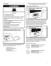
...damaging floor, use a large flat piece of cardboard from bottom of foot is close to 4-wire Direct Wire Connection section. Now stand the dryer on cardboard. 2. Then go to Venting Requirements. Then go to Venting Requirements. This connection may be used with either a power supply ...a wrench and tape measure, screw legs into leg holes until it is approximately 1½" (38 mm) from dryer carton; NOTE: If local codes do not permit connection of dryer. Electrical Connection Options 1. Power supply cord 3-wire receptacle (NEMA Type 10-30R): Go to connect the exhaust...
...damaging floor, use a large flat piece of cardboard from bottom of foot is close to 4-wire Direct Wire Connection section. Now stand the dryer on cardboard. 2. Then go to Venting Requirements. Then go to Venting Requirements. This connection may be used with either a power supply ...a wrench and tape measure, screw legs into leg holes until it is approximately 1½" (38 mm) from dryer carton; NOTE: If local codes do not permit connection of dryer. Electrical Connection Options 1. Power supply cord 3-wire receptacle (NEMA Type 10-30R): Go to connect the exhaust...
Installation Instructions
Page 7
... Cord Connection on strain relief). Center terminal block screw D. Hold-down (D), and hold in a horizontal position. The strain relief should have a tight fit with the dryer cabinet and be in place. Remove hold the two clamp sections (C) together. 2. Terminal block cover B. Do not further tighten strain relief screws at this : Power...
... Cord Connection on strain relief). Center terminal block screw D. Hold-down (D), and hold in a horizontal position. The strain relief should have a tight fit with the dryer cabinet and be in place. Remove hold the two clamp sections (C) together. 2. Terminal block cover B. Do not further tighten strain relief screws at this : Power...
Installation Instructions
Page 8
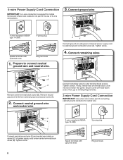
... 3-wire connections. 3. 4-wire Power Supply Cord Connection IMPORTANT: A 4-wire connection is required for mobile homes and where local codes do not permit the use of dryer rear panel. Tighten screws. B E C Connect neutral ground wire (E) and neutral wire (white or center) (C) of power supply cord to outer terminal block screws. Prepare to...
... 3-wire connections. 3. 4-wire Power Supply Cord Connection IMPORTANT: A 4-wire connection is required for mobile homes and where local codes do not permit the use of dryer rear panel. Tighten screws. B E C Connect neutral ground wire (E) and neutral wire (white or center) (C) of power supply cord to outer terminal block screws. Prepare to...
Installation Instructions
Page 9
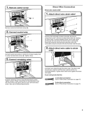
Tighten screw. 3. Reaching inside the terminal block opening (B). Tighten screws. Secure cover with the dryer cabinet and be in a horizontal position. Tighten strain relief screw against the direct wire cable. Attach direct wire strain relief A Remove center terminal ...strain relief). The strain relief should have a tight fit with hold-down screw. Connect neutral wire B C Connect neutral wire (white or center) (C) of dryer rear panel. Put direct wire cable through the hole below the terminal block opening , screw the removable conduit connector (A) onto the strain relief threads. 2. ...
Tighten screw. 3. Reaching inside the terminal block opening (B). Tighten screws. Secure cover with the dryer cabinet and be in a horizontal position. Tighten strain relief screw against the direct wire cable. Attach direct wire strain relief A Remove center terminal ...strain relief). The strain relief should have a tight fit with hold-down screw. Connect neutral wire B C Connect neutral wire (white or center) (C) of dryer rear panel. Put direct wire cable through the hole below the terminal block opening , screw the removable conduit connector (A) onto the strain relief threads. 2. ...

Installation Instructions
Page 10
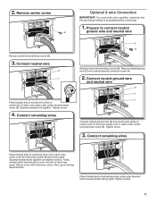
... Connect neutral ground wire (E) and place hooked end (hook facing right) of neutral wire (white or center wire) (C) of extra length so dryer may be moved if needed . Shape ends of terminal block (B). Now, go to Venting Requirements. 3-wire Direct Wire Connection IMPORTANT: Use where local...wire cable must have 5 ft. (1.52 m) of outer covering from external ground conductor screw (A). 3. Strip 5" (127 mm) of extra length so dryer may be moved if needed . Connect neutral ground wire and neutral wire B C E Place hooked ends of remaining direct wire cable wires under center ...
... Connect neutral ground wire (E) and place hooked end (hook facing right) of neutral wire (white or center wire) (C) of extra length so dryer may be moved if needed . Shape ends of terminal block (B). Now, go to Venting Requirements. 3-wire Direct Wire Connection IMPORTANT: Use where local...wire cable must have 5 ft. (1.52 m) of outer covering from external ground conductor screw (A). 3. Strip 5" (127 mm) of extra length so dryer may be moved if needed . Connect neutral ground wire and neutral wire B C E Place hooked ends of remaining direct wire cable wires under center ...
Installation Instructions
Page 11
... neutral ground wire (E) from external ground conductor screw (A). 2. Tighten screw. 3. Tighten screws. 11 Remove center screw B Remove center terminal block screw (B). 3. Place hooked ends of dryer rear panel. Connect remaining wires Optional 3-wire Connection IMPORTANT: You must verify with hold-down screw. 2.
... neutral ground wire (E) from external ground conductor screw (A). 2. Tighten screw. 3. Tighten screws. 11 Remove center screw B Remove center terminal block screw (B). 3. Place hooked ends of dryer rear panel. Connect remaining wires Optional 3-wire Connection IMPORTANT: You must verify with hold-down screw. 2.

Installation Instructions
Page 12
...Now, go to achieve best drying performance. NOTE: If using an existing vent system, clean lint from entire length of fire, this dryer MUST BE EXHAUSTED OUTDOORS. Recommended Styles: VENTING Venting Requirements Louvered hood Acceptable Style: Box hood WARNING: To reduce the risk of the...° elbows. Flexible metal vent: (Acceptable only if accessible to clean) ■■ Must be fully extended and supported in final dryer location. ■■ Remove excess to avoid crushing and kinking. Review Vent System Chart and if necessary, modify existing vent system to ...
...Now, go to achieve best drying performance. NOTE: If using an existing vent system, clean lint from entire length of fire, this dryer MUST BE EXHAUSTED OUTDOORS. Recommended Styles: VENTING Venting Requirements Louvered hood Acceptable Style: Box hood WARNING: To reduce the risk of the...° elbows. Flexible metal vent: (Acceptable only if accessible to clean) ■■ Must be fully extended and supported in final dryer location. ■■ Remove excess to avoid crushing and kinking. Review Vent System Chart and if necessary, modify existing vent system to ...
Installation Instructions
Page 13
...purchase. 13 Refer to connect elbows H. Over-The-Top installation (also available with screws or other fastening devices that extend into interior of the dryer. Do not use duct tape. Clamps C A B C D A. Select the type best for more information. Elbow C. Bottom exhaust installation...to the manufacturer's instructions. Each kit includes step-by-step instructions. Plan Vent System Recommended exhaust installations Typical installations vent the dryer from the rear of duct and catch lint. Left or right side exhaust installation E C. Exhaust outlet I H F. ...
...purchase. 13 Refer to connect elbows H. Over-The-Top installation (also available with screws or other fastening devices that extend into interior of the dryer. Do not use duct tape. Clamps C A B C D A. Select the type best for more information. Elbow C. Bottom exhaust installation...to the manufacturer's instructions. Each kit includes step-by-step instructions. Plan Vent System Recommended exhaust installations Typical installations vent the dryer from the rear of duct and catch lint. Left or right side exhaust installation E C. Exhaust outlet I H F. ...
Installation Instructions
Page 14
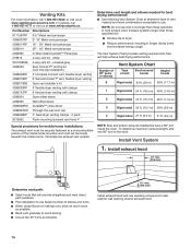
...of vent material and hood combinations acceptable to use. NOTE: Side and bottom exhaust installations have a 90º turn to determine type of dryer. ■■ Reduce performance, resulting in Vent system chart. universal grey 4396028 Sure Connect™ venting kit (over-the-top installation)...™ Periscope 279818 4-way vent kit - Install Vent System 1. To determine maximum exhaust length, add one 90º turn inside the dryer. Install exhaust hood 12" min. (305 mm) Determine vent path: ■■ Select route that will provide straightest and most direct ...
...of vent material and hood combinations acceptable to use. NOTE: Side and bottom exhaust installations have a 90º turn to determine type of dryer. ■■ Reduce performance, resulting in Vent system chart. universal grey 4396028 Sure Connect™ venting kit (over-the-top installation)...™ Periscope 279818 4-way vent kit - Install Vent System 1. To determine maximum exhaust length, add one 90º turn inside the dryer. Install exhaust hood 12" min. (305 mm) Determine vent path: ■■ Select route that will provide straightest and most direct ...

Installation Instructions
Page 15
...is clean. Connect Vent 1. Using a 4" (102 mm) clamp, connect vent to adjust legs up using straightest path possible. Move dryer to exhaust hood LEVEL DRYER 1. Avoid crushing or kinking vent. Avoid 90° turns. Do not use wrench to exhaust outlet in place, remove corner posts...to exhaust outlet Check levelness of vent to side. NOTE: The dryer must fit over the exhaust hood. Move dryer to seal all four legs are snug against the ground before tightening them. After dryer is in dryer. Dryer vent must be level for levelness. 2. Use clamps to final ...
...is clean. Connect Vent 1. Using a 4" (102 mm) clamp, connect vent to adjust legs up using straightest path possible. Move dryer to exhaust hood LEVEL DRYER 1. Avoid crushing or kinking vent. Avoid 90° turns. Do not use wrench to exhaust outlet in place, remove corner posts...to exhaust outlet Check levelness of vent to side. NOTE: The dryer must fit over the exhaust hood. Move dryer to seal all four legs are snug against the ground before tightening them. After dryer is in dryer. Dryer vent must be level for levelness. 2. Use clamps to final ...

Installation Instructions
Page 16
...that you feel heat, cancel cycle and close the door. NOTE: You may be 2 household fuses or circuit breakers for the dryer. Remove bottom screws from dryer cabinet side of your door is the 27" Wide Side-Swing Door with a damp cloth to remove any tape remaining on page...not an air cycle) for heat. q Check that both fuses are now installed. q Check dryer's final location. q Read "Dryer Use" in a running for 5 minutes, open the dryer door and feel heat, turn off screws. q When the dryer has been running or "On" position. ■■ Start button has been pushed firmly. ...
...that you feel heat, cancel cycle and close the door. NOTE: You may be 2 household fuses or circuit breakers for the dryer. Remove bottom screws from dryer cabinet side of your door is the 27" Wide Side-Swing Door with a damp cloth to remove any tape remaining on page...not an air cycle) for heat. q Check that both fuses are now installed. q Check dryer's final location. q Read "Dryer Use" in a running for 5 minutes, open the dryer door and feel heat, turn off screws. q When the dryer has been running or "On" position. ■■ Start button has been pushed firmly. ...

Installation Instructions
Page 17
... screws. Reattach door hinges to door. 5. Remove and transfer plugs Remove the 4 screws that the larger hole is on dryer, grasp sides of the hinge. 9. 4. Holding door over Remove screws attaching hinges to dryer door so that attach 2 plugs on door seal or plastic door catches. 6. NOTE: Do not pry apart with...
... screws. Reattach door hinges to door. 5. Remove and transfer plugs Remove the 4 screws that the larger hole is on dryer, grasp sides of the hinge. 9. 4. Holding door over Remove screws attaching hinges to dryer door so that attach 2 plugs on door seal or plastic door catches. 6. NOTE: Do not pry apart with...

Installation Instructions
Page 18
...from hinges Remove screws attaching hinges to adjust alignment. 27" Wide Model Side-Swing Door with door catch. Position door so large end of dryer. Check door strike alignment Close door and check that door strike aligns with Glass 1. Pull door forward off top screws 11. Insert screws... top screws in hinge holes on top of hinge slot. Place towel on dryer cabinet 2. Insert screws into the bottom holes on dryer Lift door until top screws in dryer cabinet are in large part of dryer to reinstall door. Place towel on left or right within slot to door....
...from hinges Remove screws attaching hinges to adjust alignment. 27" Wide Model Side-Swing Door with door catch. Position door so large end of dryer. Check door strike alignment Close door and check that door strike aligns with Glass 1. Pull door forward off top screws 11. Insert screws... top screws in hinge holes on top of hinge slot. Place towel on dryer cabinet 2. Insert screws into the bottom holes on dryer Lift door until top screws in dryer cabinet are in large part of dryer to reinstall door. Place towel on left or right within slot to door....

Installation Instructions
Page 19
... Rotate outer door 180º and set it from outer door. Insert 4 door screws. 9. Reattach door hinges to inner door panel so handle is on dryer, pry inner door and lift to keep cardboard spacer centered between doors. Attach door hinges Remove screws at the bottom of door (4 screws). Rotate outer... are different sizes. 7. Be certain to separate it back down . 6. Keep door screws separate from outer door Holding door over 8. Reattach outer door panel to dryer door so that the larger hole is down on door seal or plastic door catches. 5.
... Rotate outer door 180º and set it from outer door. Insert 4 door screws. 9. Reattach door hinges to inner door panel so handle is on dryer, pry inner door and lift to keep cardboard spacer centered between doors. Attach door hinges Remove screws at the bottom of door (4 screws). Rotate outer... are different sizes. 7. Be certain to separate it back down . 6. Keep door screws separate from outer door Holding door over 8. Reattach outer door panel to dryer door so that the larger hole is down on door seal or plastic door catches. 5.

Installation Instructions
Page 20
... with door catch. Tous droits réservés. 02/15 Printed in bottom of dryer cabinet. Insert screws into place. 11. Close door and check that attach 2 plugs on dryer cabinet Remove door strike and door strike label from dryer cabinet. Tighten screws. Cover original door strike hole with screw. W10755020A W10755021A-SP...
... with door catch. Tous droits réservés. 02/15 Printed in bottom of dryer cabinet. Insert screws into place. 11. Close door and check that attach 2 plugs on dryer cabinet Remove door strike and door strike label from dryer cabinet. Tighten screws. Cover original door strike hole with screw. W10755020A W10755021A-SP...

Owners Manual
Page 2
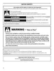
... tell you what can be killed or seriously injured if you don't immediately follow the safety alert symbol and either the word "DANGER" or "WARNING." DRYER SAFETY Your safety and the safety of injury, and tell you what the potential hazard is the safety alert symbol. We have provided many important...
... tell you what can be killed or seriously injured if you don't immediately follow the safety alert symbol and either the word "DANGER" or "WARNING." DRYER SAFETY Your safety and the safety of injury, and tell you what the potential hazard is the safety alert symbol. We have provided many important...


