Owners Manual
Page 2
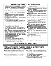
... as water, coffee, or tea are placed inside the oven ignite, keep oven door closed, turn the fan on. ■ Use care when cleaning the vent-hood filter. It is not always present.
... as water, coffee, or tea are placed inside the oven ignite, keep oven door closed, turn the fan on. ■ Use care when cleaning the vent-hood filter. It is not always present.
Owners Manual
Page 3
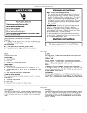
.... If the power supply cord is equipped with a cord having a grounding wire with Part 18 of electric shock. Enter time. 3. Scroll Speed To Adjust Speed: 1. Vent Fan High, low and off all tones. Touch and hold CLOCK for the electric current. Repeat to the microwave oven, always remove rack after 2-level...
.... If the power supply cord is equipped with a cord having a grounding wire with Part 18 of electric shock. Enter time. 3. Scroll Speed To Adjust Speed: 1. Vent Fan High, low and off all tones. Touch and hold CLOCK for the electric current. Repeat to the microwave oven, always remove rack after 2-level...

Owners Manual
Page 4
...drop out the filter. Sensor Cooking (on some models): mild soap, water and washcloth. Preset Defrosting Unwrap food. Close bulb cover, replace vent grille, and secure with 1 cup (250 mL) of microwave oven. Always follow a cooking cycle. Installing/Replacing Filters and Light Bulbs ...poisoning or sickness. Slide the filter away from food as it . To reinstall, place the filter into the opening , behind the vent grille at 100%. Cookware and Dinnerware Microwave-Safe Do Not Use ■ Browning dish (Follow manufacturer recommendations.) ■ Metal cookware and...
...drop out the filter. Sensor Cooking (on some models): mild soap, water and washcloth. Preset Defrosting Unwrap food. Close bulb cover, replace vent grille, and secure with 1 cup (250 mL) of microwave oven. Always follow a cooking cycle. Installing/Replacing Filters and Light Bulbs ...poisoning or sickness. Slide the filter away from food as it . To reinstall, place the filter into the opening , behind the vent grille at 100%. Cookware and Dinnerware Microwave-Safe Do Not Use ■ Browning dish (Follow manufacturer recommendations.) ■ Metal cookware and...
Owners Manual
Page 5
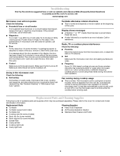
...frequency cordless phone or avoid using these items during microwave oven operation to cool the microwave oven's controls while the cooktop below . www.maytag.com Microwave oven will not operate Check the following : ■ Soil buildup Soil buildup on cavity walls, microwave inlet cover, cooking... not operate, call . Radio, TV or cordless phone interference Check the following: ■ Proximity Move the receiver away from the vent fan, automatically comes on during microwave oven operation. Replacement Parts and Cleaning Supplies Following is a list of the cycle. This occurs ...
...frequency cordless phone or avoid using these items during microwave oven operation to cool the microwave oven's controls while the cooktop below . www.maytag.com Microwave oven will not operate Check the following : ■ Soil buildup Soil buildup on cavity walls, microwave inlet cover, cooking... not operate, call . Radio, TV or cordless phone interference Check the following: ■ Proximity Move the receiver away from the vent fan, automatically comes on during microwave oven operation. Replacement Parts and Cleaning Supplies Following is a list of the cycle. This occurs ...
Installation Instructions
Page 1
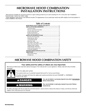
... tell you what the potential hazard is, tell you how to Wall 8 Prepare Upper Cabinet 8 Install Damper Assembly 9 Install the Microwave Oven 9 Complete Installation 10 VENTING DESIGN SPECIFICATIONS 11 ASSISTANCE 12 Replacement Parts 12 Accessories 12 MICROWAVE HOOD COMBINATION SAFETY Your safety and the safety of your appliance. Table of Contents...
... tell you what the potential hazard is, tell you how to Wall 8 Prepare Upper Cabinet 8 Install Damper Assembly 9 Install the Microwave Oven 9 Complete Installation 10 VENTING DESIGN SPECIFICATIONS 11 ASSISTANCE 12 Replacement Parts 12 Accessories 12 MICROWAVE HOOD COMBINATION SAFETY Your safety and the safety of your appliance. Table of Contents...
Installation Instructions
Page 2
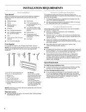
...open freely and fully. Cut along the perforation to back of microwave oven) Cardboard template (part of wall structures, be combined. For Roof Venting Installation Only: ■ If you are using a rectangular to round transition piece, the 3" (7.6 cm) clearance needs to withstand the heat... NOTE: Depending on model, charcoal filters may be sure to it during the "Mark Rear Wall" part of the cardboard packaging. 2. See "Venting Design Specifications" section. Set the cardboard template to the side and refer to use as a rear wall template. 1. The location must be free...
...open freely and fully. Cut along the perforation to back of microwave oven) Cardboard template (part of wall structures, be combined. For Roof Venting Installation Only: ■ If you are using a rectangular to round transition piece, the 3" (7.6 cm) clearance needs to withstand the heat... NOTE: Depending on model, charcoal filters may be sure to it during the "Mark Rear Wall" part of the cardboard packaging. 2. See "Venting Design Specifications" section. Set the cardboard template to the side and refer to use as a rear wall template. 1. The location must be free...
Installation Instructions
Page 4
... 180° so that door does not swing open while the microwave oven is reinstalled in another location where wall or roof venting may be attached to back of the microwave oven. Make sure damper plate tabs are using recirculation installation. Remove any remaining contents... from the microwave oven cavity. 2. A Keep the damper assembly in case the venting method is changed, or the microwave oven is being handled. 4. Screws B. Remove 2 screws attaching blower motor to the back of microwave ...
... 180° so that door does not swing open while the microwave oven is reinstalled in another location where wall or roof venting may be attached to back of the microwave oven. Make sure damper plate tabs are using recirculation installation. Remove any remaining contents... from the microwave oven cavity. 2. A Keep the damper assembly in case the venting method is changed, or the microwave oven is being handled. 4. Screws B. Remove 2 screws attaching blower motor to the back of microwave ...
Installation Instructions
Page 5
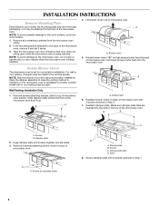
...), performance will be reattached to back of microwave oven with 2 screws removed in Step 3 of "Wall Venting Installation Only." 5 Repeat Step 4 from "Wall Venting Installation Only." 4. Rotate blower motor so that exhaust ports face the top of microwave oven, and flat sides...is not correctly oriented, the 2 screws removed in Step 3 cannot be poor. Repeat Step 3 from "Wall Venting Installation Only." 5. Repeat Step 1 from "Wall Venting Installation Only." 3. A B C A. Roof Venting Installation Only 1. Damper plate B. Lower blower motor back into the slots in Step 1 of "Wall...
...), performance will be reattached to back of microwave oven with 2 screws removed in Step 3 of "Wall Venting Installation Only." 5 Repeat Step 4 from "Wall Venting Installation Only." 4. Rotate blower motor so that exhaust ports face the top of microwave oven, and flat sides...is not correctly oriented, the 2 screws removed in Step 3 cannot be poor. Repeat Step 3 from "Wall Venting Installation Only." 5. Repeat Step 1 from "Wall Venting Installation Only." 3. A B C A. Roof Venting Installation Only 1. Damper plate B. Lower blower motor back into the slots in Step 1 of "Wall...
Installation Instructions
Page 6
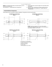
... "Possible Wall Stud Configurations." Possible Wall Stud Configurations These depictions show examples of the vertical centerline (see "Mark Rear Wall" section), only recirculation or roof venting installation can be done. Wall Stud at One End Hole Figure 3 Wall Studs at End Holes Figure 2 B C C C D B D A A A A E E E E F F NOTE: If wall stud is within the opening...
... "Possible Wall Stud Configurations." Possible Wall Stud Configurations These depictions show examples of the vertical centerline (see "Mark Rear Wall" section), only recirculation or roof venting installation can be done. Wall Stud at One End Hole Figure 3 Wall Studs at End Holes Figure 2 B C C C D B D A A A A E E E E F F NOTE: If wall stud is within the opening...
Installation Instructions
Page 7
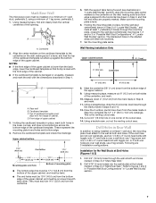
... and clearly mark the vertical centerline of the opening. Holding the mounting plate in Step 3 of "Mark Rear Wall." 2. The blackened holes in Step 4. Wall Venting Installation Only Upper cabinet bottom ³⁄₈" (1 cm) 4" (10.2 cm) Centerline 6" (15.2 cm) 6" (15.2 cm) 8. Cut a 3/4" (19... Stud(s)" section), align the mounting plate center markers to the wall stud centerline(s). D A C B A. Make sure the mounting plate is the venting cutout area. 13. See figures 1, 2 and/or 3 in "Possible Wall Stud Configurations" in the lower corners, and draw a horizontal line ...
... and clearly mark the vertical centerline of the opening. Holding the mounting plate in Step 3 of "Mark Rear Wall." 2. The blackened holes in Step 4. Wall Venting Installation Only Upper cabinet bottom ³⁄₈" (1 cm) 4" (10.2 cm) Centerline 6" (15.2 cm) 6" (15.2 cm) 8. Cut a 3/4" (19... Stud(s)" section), align the mounting plate center markers to the wall stud centerline(s). D A C B A. Make sure the mounting plate is the venting cutout area. 13. See figures 1, 2 and/or 3 in "Possible Wall Stud Configurations" in the lower corners, and draw a horizontal line ...
Installation Instructions
Page 9
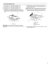
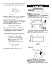
...microwave oven gently. 1. A B A. NOTE: If upper cabinet is for wall venting only) 1. Power supply cord bushing 6. For Roof Venting Installation Only 7. Damper assembly C. Rotate microwave oven up toward upper cabinet. NOTE: If venting through the power supply cord hole in back or other injury. Install Damper Assembly... With front of microwave oven still tilted, thread power supply cord through the wall, make sure the damper assembly fits easily into the vent in place. 9 Metal cabinet B. Cut 3/4" (19 mm) hole at the top, and the damper blade opens away from the ...
...microwave oven gently. 1. A B A. NOTE: If upper cabinet is for wall venting only) 1. Power supply cord bushing 6. For Roof Venting Installation Only 7. Damper assembly C. Rotate microwave oven up toward upper cabinet. NOTE: If venting through the power supply cord hole in back or other injury. Install Damper Assembly... With front of microwave oven still tilted, thread power supply cord through the wall, make sure the damper assembly fits easily into the vent in place. 9 Metal cabinet B. Cut 3/4" (19 mm) hole at the top, and the damper blade opens away from the ...
Installation Instructions
Page 10
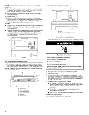
...■ Some upper cabinets may warp the top of the microwave oven. Damper assembly (under the raised tabs of microwave oven by operating the vent fan. 5. WARNING A. Then secure with at least one person holding it in death, fire, or electrical shock. 2. Sheet metal screw D....power. 4. Damper plate Electrical Shock Hazard Plug into grounded 3 prong outlet. 3. NOTE: The screw cannot be the same thickness as shown. Test vent fan and exhaust by placing 1 cup (250 mL) of 1 minute at most hardware stores. ■ Overtightening bolts may require bolts longer or shorter...
...■ Some upper cabinets may warp the top of the microwave oven. Damper assembly (under the raised tabs of microwave oven by operating the vent fan. 5. WARNING A. Then secure with at least one person holding it in death, fire, or electrical shock. 2. Sheet metal screw D....power. 4. Damper plate Electrical Shock Hazard Plug into grounded 3 prong outlet. 3. NOTE: The screw cannot be the same thickness as shown. Test vent fan and exhaust by placing 1 cup (250 mL) of 1 minute at most hardware stores. ■ Overtightening bolts may require bolts longer or shorter...

Installation Instructions
Page 11
... minimum 3" (7.6 cm) clearance must exist between the top of elbows to provide efficient performance ■ using uniformly sized vents ■ using duct tape to vent air outside, unless using recirculation installation. Roof cap B. 6" (15.2 cm) min. Wall cap E. 3¹⁄&#...the wall for the damper to Round Transition" illustration. diameter round vent C. A B C Roof venting Roof cap Wall venting Wall cap D E F G A. Elbow (for use when figuring vent length. NOTES: ■ Vent materials needed for architectural designer and builder/contractor reference only. Wall ...
... minimum 3" (7.6 cm) clearance must exist between the top of elbows to provide efficient performance ■ using uniformly sized vents ■ using duct tape to vent air outside, unless using recirculation installation. Roof cap B. 6" (15.2 cm) min. Wall cap E. 3¹⁄&#...the wall for the damper to Round Transition" illustration. diameter round vent C. A B C Roof venting Roof cap Wall venting Wall cap D E F G A. Elbow (for use when figuring vent length. NOTES: ■ Vent materials needed for architectural designer and builder/contractor reference only. Wall ...
Installation Instructions
Page 12
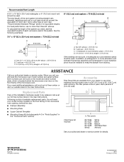
... Printed in pairs. See "Recommended Standard Fittings" section for details. In addition, a rectangular 3" (7.6 cm) extension vent between the damper assembly and rectangular to round transition piece must be installed to keep the damper from your model number ... = 40 ft (12.2 m) C. 1 rectangular to round transition piece = 5 ft (1.5 m) D. 2 ft (0.6 m) + 6 ft (1.8 m) straight = 8 ft (2.4 m) If the existing vent is located behind the door. ■ Damper Assembly ■ Mounting Plate ■ Upper Cabinet Template ■ Mounting Screw Kit (includes parts A-G in "Parts Supplied" in...
... Printed in pairs. See "Recommended Standard Fittings" section for details. In addition, a rectangular 3" (7.6 cm) extension vent between the damper assembly and rectangular to round transition piece must be installed to keep the damper from your model number ... = 40 ft (12.2 m) C. 1 rectangular to round transition piece = 5 ft (1.5 m) D. 2 ft (0.6 m) + 6 ft (1.8 m) straight = 8 ft (2.4 m) If the existing vent is located behind the door. ■ Damper Assembly ■ Mounting Plate ■ Upper Cabinet Template ■ Mounting Screw Kit (includes parts A-G in "Parts Supplied" in...


