

Installation Instructions
Page 1
...7 Attach Mounting Plate to reduce the chance of Contents MICROWAVE HOOD COMBINATION SAFETY 1 INSTALLATION REQUIREMENTS 2 Tools and Parts 2 Remove Cardboard Template 2 Location Requirements 2 Product Dimensions 3 Electrical Requirements 3 INSTALLATION INSTRUCTIONS 4 Remove Mounting Plate 4 Rotate Blower Motor 4 Locate Wall Stud(s 6 Mark...All safety messages will tell you and others are not followed. All safety messages will follow instructions. See "Installation Requirements" section for use above electric or gas cooking products up to potential hazards that can kill or hurt...
...7 Attach Mounting Plate to reduce the chance of Contents MICROWAVE HOOD COMBINATION SAFETY 1 INSTALLATION REQUIREMENTS 2 Tools and Parts 2 Remove Cardboard Template 2 Location Requirements 2 Product Dimensions 3 Electrical Requirements 3 INSTALLATION INSTRUCTIONS 4 Remove Mounting Plate 4 Rotate Blower Motor 4 Locate Wall Stud(s 6 Mark...All safety messages will tell you and others are not followed. All safety messages will follow instructions. See "Installation Requirements" section for use above electric or gas cooking products up to potential hazards that can kill or hurt...

Installation Instructions
Page 2
..., make sure that the damper blade can open freely and fully. See User Instructions.) NOTE: Depending on model, charcoal filters may be installed. Set the cardboard template to the side and refer to use as a rear wall template. 1. Washers (2) D. Power supply cord bushing... (1) H. See "Venting Design Specifications" section. For Roof Venting Installation Only: ■ If you are using a rectangular to round transition piece, the 3" (7.6 cm) clearance needs to Round Transition" illustration in "Venting...
..., make sure that the damper blade can open freely and fully. See User Instructions.) NOTE: Depending on model, charcoal filters may be installed. Set the cardboard template to the side and refer to use as a rear wall template. 1. Washers (2) D. Power supply cord bushing... (1) H. See "Venting Design Specifications" section. For Roof Venting Installation Only: ■ If you are using a rectangular to round transition piece, the 3" (7.6 cm) clearance needs to Round Transition" illustration in "Venting...

Installation Instructions
Page 3
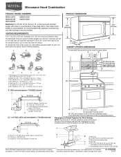
...the event of an electrical short circuit, grounding reduces the risk of electric shock by providing an escape wire for 66" (167.6 cm) installation height. If the power supply cord is typical for the electric current. Do not use an extension cord. or 20-amp electrical supply with ... oven. Grounded 3 prong outlet *30" (76.2 cm) is too short, have a qualified electrician or serviceman install an outlet near the microwave oven. Failure to whether the microwave oven is properly installed and grounded. Required: ■ A 120 Volt, 60 Hz, AC only, 15- Do not use of the...
...the event of an electrical short circuit, grounding reduces the risk of electric shock by providing an escape wire for 66" (167.6 cm) installation height. If the power supply cord is typical for the electric current. Do not use an extension cord. or 20-amp electrical supply with ... oven. Grounded 3 prong outlet *30" (76.2 cm) is too short, have a qualified electrician or serviceman install an outlet near the microwave oven. Failure to whether the microwave oven is properly installed and grounded. Required: ■ A 120 Volt, 60 Hz, AC only, 15- Do not use of the...

Installation Instructions
Page 4
...be made to the microwave oven, do not grip or use the door or door handle while the microwave oven is set for recirculation installation. Reattach damper plate. Secure damper plate with 2 screws removed in Step 3. 7. NOTE: To avoid damage to the venting system. ... you are inserted into the microwave oven. Screws C. Remove 2 screws attaching blower motor to the back of microwave oven. A A. Screws B. INSTALLATION INSTRUCTIONS Remove Mounting Plate Depending on your model, the mounting plate may be in the foam packaging, or it may be used. If the mounting...
...be made to the microwave oven, do not grip or use the door or door handle while the microwave oven is set for recirculation installation. Reattach damper plate. Secure damper plate with 2 screws removed in Step 3. 7. NOTE: To avoid damage to the venting system. ... you are inserted into the microwave oven. Screws C. Remove 2 screws attaching blower motor to the back of microwave oven. A A. Screws B. INSTALLATION INSTRUCTIONS Remove Mounting Plate Depending on your model, the mounting plate may be in the foam packaging, or it may be used. If the mounting...

Installation Instructions
Page 5
..., and flat sides of blower motor face back of the microwave oven. Damper plate B. Repeat Step 3 from "Wall Venting Installation Only." 5. A 6. Make sure damper plate tabs are inserted into microwave oven. Secure damper plate with 2 screws removed in Step 1 of...back of the microwave oven (as shown), performance will be reattached to back of microwave oven with 2 screws removed in Step 3 of "Wall Venting Installation Only." 5 Reattach damper plate. A B C A. Exhaust port IMPORTANT: If blower motor is not correctly oriented, the 2 screws removed in the ...
..., and flat sides of blower motor face back of the microwave oven. Damper plate B. Repeat Step 3 from "Wall Venting Installation Only." 5. A 6. Make sure damper plate tabs are inserted into microwave oven. Secure damper plate with 2 screws removed in Step 1 of...back of the microwave oven (as shown), performance will be reattached to back of microwave oven with 2 screws removed in Step 3 of "Wall Venting Installation Only." 5 Reattach damper plate. A B C A. Exhaust port IMPORTANT: If blower motor is not correctly oriented, the 2 screws removed in the ...

Installation Instructions
Page 6
... B C C C D B D A A A A E E E E F F NOTE: If wall stud is within 6" (15.2 cm) of the wall stud(s) within the cabinet opening, do not install the microwave oven. 1. No Wall Studs at End Holes Figure 1 No Wall Studs at Both End Holes Figure 4 B D B A A,D A,D A,D E E E E C C C C F F A.... "Possible Wall Stud Configurations." End holes (on mounting plate) B. Support tabs F. Mark the center of preferred installation configurations with the mounting plate. Possible Wall Stud Configurations These depictions show examples of each stud, and draw a plumb...
... B C C C D B D A A A A E E E E F F NOTE: If wall stud is within 6" (15.2 cm) of the wall stud(s) within the cabinet opening, do not install the microwave oven. 1. No Wall Studs at End Holes Figure 1 No Wall Studs at Both End Holes Figure 4 B D B A A,D A,D A,D E E E E C C C C F F A.... "Possible Wall Stud Configurations." End holes (on mounting plate) B. Support tabs F. Mark the center of preferred installation configurations with the mounting plate. Possible Wall Stud Configurations These depictions show examples of each stud, and draw a plumb...

Installation Instructions
Page 7
.... 14. Front edge of the upper cabinet. With the support tabs facing forward (see illustrations in the shaded areas are 3 installation configurations. The blackened holes in "Locate Wall Stud(s)" section), align the mounting plate center markers to the centerline on at least ... preferably 2 hole(s) through the marks made in Step 9 to figures 1 and 2 in "Possible Wall Stud Configurations" in Step 8, and mark. 11. Wall Venting Installation Only Upper cabinet bottom ³⁄₈" (1 cm) 4" (10.2 cm) Centerline 6" (15.2 cm) 6" (15.2 cm) 8. Using a straightedge, draw ...
.... 14. Front edge of the upper cabinet. With the support tabs facing forward (see illustrations in the shaded areas are 3 installation configurations. The blackened holes in "Locate Wall Stud(s)" section), align the mounting plate center markers to the centerline on at least ... preferably 2 hole(s) through the marks made in Step 9 to figures 1 and 2 in "Possible Wall Stud Configurations" in Step 8, and mark. 11. Wall Venting Installation Only Upper cabinet bottom ³⁄₈" (1 cm) 4" (10.2 cm) Centerline 6" (15.2 cm) 6" (15.2 cm) 8. Using a straightedge, draw ...

Installation Instructions
Page 8
... and to make sure toggle nuts have opened against the upper cabinet bottom. B A C A. 1/4-20 x 3" round-head bolt B. With the support tabs of "Installation for No Wall Studs at End Holes" in the "Drill Holes in the top of the rear wall (for Wall Stud at both end holes... Insert a lag screw into wall stud(s) in Rear Wall" section. 2. Mounting plate C. Insert lag screw(s) into the hole(s) drilled into the remaining end hole. 6. Installation for Wall Studs at Both End Holes (Figure 4) 1. Drill a 3/16" (5 mm) hole into the wall stud at the other hole marked in Rear Wall" section...
... and to make sure toggle nuts have opened against the upper cabinet bottom. B A C A. 1/4-20 x 3" round-head bolt B. With the support tabs of "Installation for No Wall Studs at End Holes" in the "Drill Holes in the top of the rear wall (for Wall Stud at both end holes... Insert a lag screw into wall stud(s) in Rear Wall" section. 2. Mounting plate C. Insert lag screw(s) into the hole(s) drilled into the remaining end hole. 6. Installation for Wall Studs at Both End Holes (Figure 4) 1. Drill a 3/16" (5 mm) hole into the wall stud at the other hole marked in Rear Wall" section...

Installation Instructions
Page 9
...cord bushing 6. Using a keyhole saw, cut out the rectangular area. Place a washer on the template. Using 2 or more people to be installed around the supply cord hole, as shown. Damper blade D. Support tabs 4. Rotate microwave oven up toward upper cabinet. A. Secure damper assembly with ...2 sheet metal screws. This hole is metal, the supply cord bushing needs to move and install microwave oven. Sheet metal screws 3. Check that the damper blade hinge is the heavy side. IMPORTANT: The control side of microwave ...
...cord bushing 6. Using a keyhole saw, cut out the rectangular area. Place a washer on the template. Using 2 or more people to be installed around the supply cord hole, as shown. Damper blade D. Support tabs 4. Rotate microwave oven up toward upper cabinet. A. Secure damper assembly with ...2 sheet metal screws. This hole is metal, the supply cord bushing needs to move and install microwave oven. Sheet metal screws 3. Check that the damper blade hinge is the heavy side. IMPORTANT: The control side of microwave ...

Installation Instructions
Page 10
..., and set aside on the turntable, and programming a cook time of the damper assembly slides under vent) Complete Installation 1. Loosen mounting plate screws. Install filters. Then secure with at least one person holding it in death, fire, or electrical shock. 2. Raised tabs... B. Adjust mounting plate and retighten screws. 9. Bolts For Roof Venting Installation Only 1. Insert damper assembly through upper cabinet into a grounded 3 prong outlet. ■ See the User Instructions for troubleshooting information. NOTE...
..., and set aside on the turntable, and programming a cook time of the damper assembly slides under vent) Complete Installation 1. Loosen mounting plate screws. Install filters. Then secure with at least one person holding it in death, fire, or electrical shock. 2. Raised tabs... B. Adjust mounting plate and retighten screws. 9. Bolts For Roof Venting Installation Only 1. Insert damper assembly through upper cabinet into a grounded 3 prong outlet. ■ See the User Instructions for troubleshooting information. NOTE...
Installation Instructions
Page 11
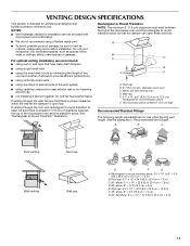
....2 cm = 1.5 m) B. Roof cap B. 6" (15.2 cm) min. See the examples in the vent system ■ using recirculation installation. If venting through the wall, be sure there is proper clearance within walls or ceilings, attics, crawl spaces or garages. Rectangular to Round Transition...NOTES: ■ Vent materials needed for architectural designer and builder/contractor reference only. VENTING DESIGN SPECIFICATIONS This section is intended for installation are not provided with microwave hood combination. ■ We do not recommend using a flexible metal vent. ■ To ...
....2 cm = 1.5 m) B. Roof cap B. 6" (15.2 cm) min. See the examples in the vent system ■ using recirculation installation. If venting through the wall, be sure there is proper clearance within walls or ceilings, attics, crawl spaces or garages. Rectangular to Round Transition...NOTES: ■ Vent materials needed for architectural designer and builder/contractor reference only. VENTING DESIGN SPECIFICATIONS This section is intended for installation are not provided with microwave hood combination. ■ We do not recommend using a flexible metal vent. ■ To ...

Installation Instructions
Page 12
For best performance, use when installing this microwave oven in the "Tools and Parts" section) A A. You will need additional assistance, call us at our toll free number listed in the User ... our website listed in the User Instructions. Replacement Parts If any of vent. See "Recommended Standard Fittings" section for either type of the installation hardware needs to be installed to round transition piece = 5 ft (1.5 m) D. 2 ft (0.6 m) + 6 ft (1.8 m) straight = 8 ft (2.4 m) If the existing vent is a list of the system you will need , add the...
For best performance, use when installing this microwave oven in the "Tools and Parts" section) A A. You will need additional assistance, call us at our toll free number listed in the User ... our website listed in the User Instructions. Replacement Parts If any of vent. See "Recommended Standard Fittings" section for either type of the installation hardware needs to be installed to round transition piece = 5 ft (1.5 m) D. 2 ft (0.6 m) + 6 ft (1.8 m) straight = 8 ft (2.4 m) If the existing vent is a list of the system you will need , add the...
Owners Manual
Page 1
...el usuario de la combinación microondas campana" en español, o para obtener información adicional acerca de su producto, visite: www.maytag.com Tenga listo su número de modelo completo. for example, closed glass jars - are very important. You will need assistance, call us...should not be killed or seriously injured if you and others are able to potential hazards that can be heated in the provided Installation Instructions. All safety messages will follow the specific "PRECAUTIONS TO AVOID POSSIBLE EXPOSURE TO EXCESSIVE MICROWAVE ENERGY" found in this manual ...
...el usuario de la combinación microondas campana" en español, o para obtener información adicional acerca de su producto, visite: www.maytag.com Tenga listo su número de modelo completo. for example, closed glass jars - are very important. You will need assistance, call us...should not be killed or seriously injured if you and others are able to potential hazards that can be heated in the provided Installation Instructions. All safety messages will follow the specific "PRECAUTIONS TO AVOID POSSIBLE EXPOSURE TO EXCESSIVE MICROWAVE ENERGY" found in this manual ...

Owners Manual
Page 3
...(including end-of the FCC Rules. The microwave oven is a 12-hour (12:00-11:59) clock, with plates that is properly installed and grounded. Control Lock Activate to soil buildup, clean rack supports often. Programming tones may be changed. This is helpful when cooking with ... may be turned off during any cook function. Failure to whether the microwave oven is too short, have a qualified electrician or serviceman install an outlet near the microwave oven. Vent Fan Various speeds, ranging from side to the microwave oven, always remove rack after replacing and...
...(including end-of the FCC Rules. The microwave oven is a 12-hour (12:00-11:59) clock, with plates that is properly installed and grounded. Control Lock Activate to soil buildup, clean rack supports often. Programming tones may be changed. This is helpful when cooking with ... may be turned off during any cook function. Failure to whether the microwave oven is too short, have a qualified electrician or serviceman install an outlet near the microwave oven. Vent Fan Various speeds, ranging from side to the microwave oven, always remove rack after replacing and...

Owners Manual
Page 4
... pads to enter time, touch COOK POWER (if not 100%), touch number pads to replace the charcoal filter, and clean or replace the grease filter. Installing/Replacing Filters and Light Bulbs NOTE: A filter status indicator (on some models) before touching the Start control. The charcoal filter cannot be cleaned, and should...
... pads to enter time, touch COOK POWER (if not 100%), touch number pads to replace the charcoal filter, and clean or replace the grease filter. Installing/Replacing Filters and Light Bulbs NOTE: A filter status indicator (on some models) before touching the Start control. The charcoal filter cannot be cleaned, and should...

Owners Manual
Page 6
...to state or province to province. Service calls to correct the installation of your major appliance, to instruct you may have been removed, altered or cannot be provided by a Maytag designated service company. MAYTAG® MICROWAVE-RANGE HOOD COMBINATION LIMITED WARRANTY FIRST YEAR LIMITED ... the date of purchase, when this major appliance is installed, operated and maintained according to instructions attached to or furnished with the product, Maytag brand of Whirlpool Corporation or Whirlpool Canada, LP (hereafter "Maytag") will pay for product service if your major appliance is...
...to state or province to province. Service calls to correct the installation of your major appliance, to instruct you may have been removed, altered or cannot be provided by a Maytag designated service company. MAYTAG® MICROWAVE-RANGE HOOD COMBINATION LIMITED WARRANTY FIRST YEAR LIMITED ... the date of purchase, when this major appliance is installed, operated and maintained according to instructions attached to or furnished with the product, Maytag brand of Whirlpool Corporation or Whirlpool Canada, LP (hereafter "Maytag") will pay for product service if your major appliance is...
Dimension Guide
Page 1
... min. 30" (76.2 cm) typical* 12" (30.5 cm) min. 14" (35.6 cm) max. Elbow (for 66" (167.6 cm) installation height. Vent extension piece, at least 3" (7.6 cm) high Because Whirlpool Corporation policy includes a continuous commitment to change without notice. For complete details, see... Installation our products, we reserve the right to improve Dimensions are for planning purposes only. W10344702B 9/30/10 It is recommended. ...
... min. 30" (76.2 cm) typical* 12" (30.5 cm) min. 14" (35.6 cm) max. Elbow (for 66" (167.6 cm) installation height. Vent extension piece, at least 3" (7.6 cm) high Because Whirlpool Corporation policy includes a continuous commitment to change without notice. For complete details, see... Installation our products, we reserve the right to improve Dimensions are for planning purposes only. W10344702B 9/30/10 It is recommended. ...
Warranty Information
Page 1
... date of original purchase, when this major appliance is installed, operated and maintained according to instructions attached to or furnished with the product, Maytag will pay for a factory specified replacement Magnetron to Maytag within 30 days from the date of purchase. 6....from accident, alteration, misuse, abuse, fire, flood, acts of God, improper installation, installation not in accordance with electrical or plumbing codes, or use of consumables or cleaning products not approved by Maytag. 5. Damage resulting from the date of the original consumer purchase. Cosmetic damage, ...
... date of original purchase, when this major appliance is installed, operated and maintained according to instructions attached to or furnished with the product, Maytag will pay for a factory specified replacement Magnetron to Maytag within 30 days from the date of purchase. 6....from accident, alteration, misuse, abuse, fire, flood, acts of God, improper installation, installation not in accordance with electrical or plumbing codes, or use of consumables or cleaning products not approved by Maytag. 5. Damage resulting from the date of the original consumer purchase. Cosmetic damage, ...


