
FS516 Installation Guide
Page 5
Contents Chapter 1 Introduction Benefits of Using Switching Technology 1-1 Types of Ethernet Switches 1-2 Model FS516 Switch Overview 1-2 Features ...1-3 Chapter 2 Physical Description Front Panel ...2-1 Fast Ethernet Ports 2-2 Normal/Uplink Push Button 2-2 LEDs ...2-3 Rear Panel ...2-4 FDX/AUTO Duplex Toggle Switches 2-4 Chapter 3 Applications Desktop Switching ...3-2 Segment Switching ...3-3 Extending a Network ...3-4 Bridging from 10BASE-T to 100BASE-TX Networks 3-5 High-Bandwidth File Servers 3-6 Contents v
Contents Chapter 1 Introduction Benefits of Using Switching Technology 1-1 Types of Ethernet Switches 1-2 Model FS516 Switch Overview 1-2 Features ...1-3 Chapter 2 Physical Description Front Panel ...2-1 Fast Ethernet Ports 2-2 Normal/Uplink Push Button 2-2 LEDs ...2-3 Rear Panel ...2-4 FDX/AUTO Duplex Toggle Switches 2-4 Chapter 3 Applications Desktop Switching ...3-2 Segment Switching ...3-3 Extending a Network ...3-4 Bridging from 10BASE-T to 100BASE-TX Networks 3-5 High-Bandwidth File Servers 3-6 Contents v
FS516 Installation Guide
Page 12
... installation with no software to configure, which saves time and minimizes the potential for configuration errors • Normal/Uplink push button to simplify network extension The switch can be connected to a hub using a simple, straight-through cable. • Protocol independence and compatibility with all common protocols such as...
... installation with no software to configure, which saves time and minimizes the potential for configuration errors • Normal/Uplink push button to simplify network extension The switch can be connected to a hub using a simple, straight-through cable. • Protocol independence and compatibility with all common protocols such as...
FS516 Installation Guide
Page 13
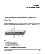
... describes the hardware features of the Model FS516 Switch Physical Description 2-1 Front Panel For easier management and control of the Model FS516 switch, familiarize yourself with the ports, LEDs, and Normal/Uplink push button on the front panel of the switch, as illustrated in Figure 2-1. 3 1 2... 16PORT 10/100Mbps Fast Ethernet Switch 100 Mbps 10 Mbps 100 Mbps 10 Mbps 1 100...
... describes the hardware features of the Model FS516 Switch Physical Description 2-1 Front Panel For easier management and control of the Model FS516 switch, familiarize yourself with the ports, LEDs, and Normal/Uplink push button on the front panel of the switch, as illustrated in Figure 2-1. 3 1 2... 16PORT 10/100Mbps Fast Ethernet Switch 100 Mbps 10 Mbps 100 Mbps 10 Mbps 1 100...

FS516 Installation Guide
Page 14
For further information about the vista RJ-45 connector and the RJ-45 plug, refer to select uplink (MDI) or normal (MDI-X) wiring for port 16 on the Model FS516 switch. The Vista RJ-45 Connector with 16 autosensing 10/100 Mbps Fast Ethernet ports. The 10/100 Mbps ports support only ... the front panel by the 100 Mbps LEDs. Installation Guide for the Model FS516 Fast Ethernet Switch Fast Ethernet Ports As Figure 2-1 shows, the Model FS516 switch is configured for uplink wiring to connect to another switch or to a hub, using an 8-pin RJ-45 plug. The network access speed for the...
For further information about the vista RJ-45 connector and the RJ-45 plug, refer to select uplink (MDI) or normal (MDI-X) wiring for port 16 on the Model FS516 switch. The Vista RJ-45 Connector with 16 autosensing 10/100 Mbps Fast Ethernet ports. The 10/100 Mbps ports support only ... the front panel by the 100 Mbps LEDs. Installation Guide for the Model FS516 Fast Ethernet Switch Fast Ethernet Ports As Figure 2-1 shows, the Model FS516 switch is configured for uplink wiring to connect to another switch or to a hub, using an 8-pin RJ-45 plug. The network access speed for the...

FS516 Installation Guide
Page 18
...the server or PC is connected. 3-2 Applications Using the Model FS516 Switch for the Model FS516 Fast Ethernet Switch Desktop Switching Figure 3-1 illustrates the Model FS516 Fast Ethernet Switch used as a desktop switch to build a small network that enables users to have 100 Mbps ...access to a file server. 1 2 4 3 8237FA Key: 1 = Server with 100 Mbps connection 2 = Model FS516 Fast Ethernet Switch (Normal/Uplink...
...the server or PC is connected. 3-2 Applications Using the Model FS516 Switch for the Model FS516 Fast Ethernet Switch Desktop Switching Figure 3-1 illustrates the Model FS516 Fast Ethernet Switch used as a desktop switch to build a small network that enables users to have 100 Mbps ...access to a file server. 1 2 4 3 8237FA Key: 1 = Server with 100 Mbps connection 2 = Model FS516 Fast Ethernet Switch (Normal/Uplink...
FS516 Installation Guide
Page 19
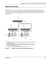
... the Model FS516 Fast Ethernet Switch segmenting networks that are built with the NETGEAR Model FE508 and Model FE516 Fast Ethernet Hubs. 1 2 3 4 5 5 6 6 8238FA Key: 1 = Model FS516 Fast Ethernet Switch (Normal/Uplink push button set to Normal position) 2 = 100 Mbps connection 3 = Model FE508 Fast Ethernet Hub (Normal/Uplink push button set to Uplink position) 4 = Model FE516 Fast...
... the Model FS516 Fast Ethernet Switch segmenting networks that are built with the NETGEAR Model FE508 and Model FE516 Fast Ethernet Hubs. 1 2 3 4 5 5 6 6 8238FA Key: 1 = Model FS516 Fast Ethernet Switch (Normal/Uplink push button set to Normal position) 2 = 100 Mbps connection 3 = Model FE508 Fast Ethernet Hub (Normal/Uplink push button set to Uplink position) 4 = Model FE516 Fast...
FS516 Installation Guide
Page 20
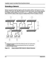
... 100 Mbps connection Figure 3-3. Figure 3-3 illustrates a network of NETGEAR Model FE508 Fast Ethernet Hubs integrated with three Model FS516 Fast Ethernet Switches. 1 1 1 2 3 3 100 m 3 3 100 m 4 4 Key: 1 = Model FS516 Fast Ethernet Switch (Normal/Uplink push button set to Uplink position) 2 = 100 Mbps connection 3 = Model FE508 Fast Ethernet Hub (Normal/Uplink push button set to 100 meters for a total...
... 100 Mbps connection Figure 3-3. Figure 3-3 illustrates a network of NETGEAR Model FE508 Fast Ethernet Hubs integrated with three Model FS516 Fast Ethernet Switches. 1 1 1 2 3 3 100 m 3 3 100 m 4 4 Key: 1 = Model FS516 Fast Ethernet Switch (Normal/Uplink push button set to Uplink position) 2 = 100 Mbps connection 3 = Model FE508 Fast Ethernet Hub (Normal/Uplink push button set to 100 meters for a total...
FS516 Installation Guide
Page 21
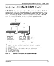
...) 6 = PCs with 10 Mbps connection 7 = PCs with 100 Mbps connection 8 = Server with the NETGEAR Model EN516 Ethernet Hub and the NETGEAR Model FE516 Fast Ethernet Hub. 1 8PORT Fiber 10/100Mbps Switch 4 2 MODEL FS562 3 5 8 6 7 8239FA Key: 1 = Model FS516 Fast Ethernet Switch (Both Normal/Uplink push buttons set to Normal position) 2 = 10 Mbps connection 3 = 100 Mbps connection...
...) 6 = PCs with 10 Mbps connection 7 = PCs with 100 Mbps connection 8 = Server with the NETGEAR Model EN516 Ethernet Hub and the NETGEAR Model FE516 Fast Ethernet Hub. 1 8PORT Fiber 10/100Mbps Switch 4 2 MODEL FS562 3 5 8 6 7 8239FA Key: 1 = Model FS516 Fast Ethernet Switch (Both Normal/Uplink push buttons set to Normal position) 2 = 10 Mbps connection 3 = 100 Mbps connection...
FS516 Installation Guide
Page 22
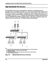
...figurable adapter card installed in the server provides up to 200 Mbps maximum data throughput. 2 2 1 3 3 4 4 5 5 8240FA Key: 1 = Model FS516 Fast Ethernet Switch (Normal/Uplink push button set to Normal position) 2 = Server with two NETGEAR Model FE508 Fast Ethernet Hubs. High-Bandwidth File Server Connection 3-6 Applications Figure 3-5 illustrates the Model FS516 Fast Ethernet...
...figurable adapter card installed in the server provides up to 200 Mbps maximum data throughput. 2 2 1 3 3 4 4 5 5 8240FA Key: 1 = Model FS516 Fast Ethernet Switch (Normal/Uplink push button set to Normal position) 2 = Server with two NETGEAR Model FE508 Fast Ethernet Hubs. High-Bandwidth File Server Connection 3-6 Applications Figure 3-5 illustrates the Model FS516 Fast Ethernet...
FS516 Installation Guide
Page 25
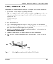
... bracket with the holes in the rack. 5 Link RX 17 Link RX 12 Normal/Uplink 24 Figure 4-1. 8242FA Attaching Mounting Brackets to the Model FS516 Switch Installation 4-3 Hold a mounting bracket against each side of the switch as illustrated in the switch. 2. Using a #1 Phillips screwdriver, tighten the screws to secure each bracket and into the...
... bracket with the holes in the rack. 5 Link RX 17 Link RX 12 Normal/Uplink 24 Figure 4-1. 8242FA Attaching Mounting Brackets to the Model FS516 Switch Installation 4-3 Hold a mounting bracket against each side of the switch as illustrated in the switch. 2. Using a #1 Phillips screwdriver, tighten the screws to secure each bracket and into the...

FS516 Installation Guide
Page 26
... Guidelines." 4-4 Installation Restricted airflow could cause overheating of space on connecting to additional switches or other devices, refer to "Connecting Devices to the Switch." The Normal/Uplink push button eliminates the need to use a straight-through twisted pair cable if the remote end... pair cable must be configured for the Model FS516 Fast Ethernet Switch 5. Install any of the ports without the Normal/Uplink push button are not blocked. Installation Guide for uplink wiring. Insert two pan-head screws with nylon washers through any additional devices...
... Guidelines." 4-4 Installation Restricted airflow could cause overheating of space on connecting to additional switches or other devices, refer to "Connecting Devices to the Switch." The Normal/Uplink push button eliminates the need to use a straight-through twisted pair cable if the remote end... pair cable must be configured for the Model FS516 Fast Ethernet Switch 5. Install any of the ports without the Normal/Uplink push button are not blocked. Installation Guide for uplink wiring. Insert two pan-head screws with nylon washers through any additional devices...
FS516 Installation Guide
Page 36
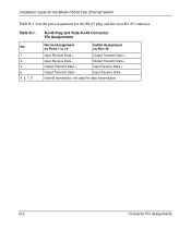
Table B-1. Input Receive Data - Internal termination, not used for the RJ-45 plug and the vista RJ-45 connector. Installation Guide for the Model FS516 Fast Ethernet Switch Table B-1 lists the pin assignments for data transmission B-2 Connector Pin Assignments Output Transmit Data - RJ-45 Plug and Vista RJ-45 Connector Pin Assignments Pin 1 2 3 6 4, 5, 7, 8 Normal Assignment on Ports 1 to 16 Uplink Assignment on Port 16 Input Receive Data + Output Transmit Data + Input Receive Data - Output Transmit Data + Input Receive Data + Output Transmit Data -
Table B-1. Input Receive Data - Internal termination, not used for the RJ-45 plug and the vista RJ-45 connector. Installation Guide for the Model FS516 Fast Ethernet Switch Table B-1 lists the pin assignments for data transmission B-2 Connector Pin Assignments Output Transmit Data - RJ-45 Plug and Vista RJ-45 Connector Pin Assignments Pin 1 2 3 6 4, 5, 7, 8 Normal Assignment on Ports 1 to 16 Uplink Assignment on Port 16 Input Receive Data + Output Transmit Data + Input Receive Data - Output Transmit Data + Input Receive Data + Output Transmit Data -
FS516 Installation Guide
Page 39
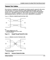
... 1 Rx 2 B 3 Tx 6 Key: B = Normal or MDI-X port (as part of the other device. Installation Guide for the Model FS516 Fast Ethernet Switch Twisted Pair Cables For two devices to communicate, the transmitter of each device must be connected to the receiver of the circuitry in crossover ports..., called MDI or uplink ports. Figure C-1 illustrates straight-through twisted pair cable. 1 Tx 2 A 3 Rx 6 1 Rx 2 B 3 Tx 6 Key: A = Uplink or MDI port (as on a hub or switch) 1, 2, 3, 6 = Pin numbers 736EA Figure C-1.
... 1 Rx 2 B 3 Tx 6 Key: B = Normal or MDI-X port (as part of the other device. Installation Guide for the Model FS516 Fast Ethernet Switch Twisted Pair Cables For two devices to communicate, the transmitter of each device must be connected to the receiver of the circuitry in crossover ports..., called MDI or uplink ports. Figure C-1 illustrates straight-through twisted pair cable. 1 Tx 2 A 3 Rx 6 1 Rx 2 B 3 Tx 6 Key: A = Uplink or MDI port (as on a hub or switch) 1, 2, 3, 6 = Pin numbers 736EA Figure C-1.

FS516 Installation Guide
Page 42
... RJ-45 connector RJ-45 plug, using for patch cables, C-4 Rx/Tx LED, 2-3 S segment switching, 1-2, 3-3 server connections, 3-6 site preparation, 4-1 straight-through twisted pair cable, 4-4, C-3 switches, duplex toggle, 1-2, 2-4, 4-5 switches, overview, 1-2 switching technology desktop switching, 1-2, 3-2 segment switching, 1-2, 3-3 T technical specifications, A-1 toggle switches, duplex, 1-2, 2-4, 4-5 troubleshooting, 5-1 U uplink ports, 2-2 wiring, 2-2, B-2, C-3 UTP cable, Category 5, C-1 V vista RJ-45 connector description, 1-4, 2-2 pin assignments, B-1 using with...
... RJ-45 connector RJ-45 plug, using for patch cables, C-4 Rx/Tx LED, 2-3 S segment switching, 1-2, 3-3 server connections, 3-6 site preparation, 4-1 straight-through twisted pair cable, 4-4, C-3 switches, duplex toggle, 1-2, 2-4, 4-5 switches, overview, 1-2 switching technology desktop switching, 1-2, 3-2 segment switching, 1-2, 3-3 T technical specifications, A-1 toggle switches, duplex, 1-2, 2-4, 4-5 troubleshooting, 5-1 U uplink ports, 2-2 wiring, 2-2, B-2, C-3 UTP cable, Category 5, C-1 V vista RJ-45 connector description, 1-4, 2-2 pin assignments, B-1 using with...


