
GS716Tv2/GS724Tv3 Hardware manual
Page 3
... and Back Panel Configuration 2-6 LED Designations ...2-7 Port LEDs ...2-7 System LEDs ...2-8 Device Hardware Interfaces 2-8 RJ-45 Ports ...2-8 SFP GBIC Module ...2-9 Factory Defaults Button 2-9 Chapter 3 Applications Desktop Switching ...3-11 Chapter 4 Installation Step 1: Preparing the Site 4-13 Step 2: Installing the Switch 4-14 Installing the Switch on a Flat Surface 4-14 Installing the Switch in a Rack 4-14 iii v1.0, June 2009
... and Back Panel Configuration 2-6 LED Designations ...2-7 Port LEDs ...2-7 System LEDs ...2-8 Device Hardware Interfaces 2-8 RJ-45 Ports ...2-8 SFP GBIC Module ...2-9 Factory Defaults Button 2-9 Chapter 3 Applications Desktop Switching ...3-11 Chapter 4 Installation Step 1: Preparing the Site 4-13 Step 2: Installing the Switch 4-14 Installing the Switch on a Flat Surface 4-14 Installing the Switch in a Rack 4-14 iii v1.0, June 2009

GS716Tv2/GS724Tv3 Hardware manual
Page 9
...pause frame flow control. • Active flow control to build the packet-forwarding information table. Reset PWR ® ProSafe 24 Port Gigabit Smart Switch 1 3 5 7 9 11 13 15 17 19 21 23 LINK/ACT SPD Green (1000M) Yellow (100M)... 23T 14 16 18 20 22 24T 23F 24F Link/ Link/ ACT ACT MODEL GS724T Auto™ Uplink Factory Defaults Figure 1-1 Introduction 1-3 v1.0, June 2009 GS716T/GS724T Hardware Installation Guide • Automatic address learning function to ...Package Contents Figure 1-1 shows the package contents of the NETGEAR GS716T and GS724T Series Smart Switch.
...pause frame flow control. • Active flow control to build the packet-forwarding information table. Reset PWR ® ProSafe 24 Port Gigabit Smart Switch 1 3 5 7 9 11 13 15 17 19 21 23 LINK/ACT SPD Green (1000M) Yellow (100M)... 23T 14 16 18 20 22 24T 23F 24F Link/ Link/ ACT ACT MODEL GS724T Auto™ Uplink Factory Defaults Figure 1-1 Introduction 1-3 v1.0, June 2009 GS716T/GS724T Hardware Installation Guide • Automatic address learning function to ...Package Contents Figure 1-1 shows the package contents of the NETGEAR GS716T and GS724T Series Smart Switch.
GS716Tv2/GS724Tv3 Hardware manual
Page 11
...NETGEAR GS716T Smart Switch front panel: System LEDs Reset PWR ® ProSafe 16 Port Gigabit Smart Switch 1 3 5 7 9 11 13 15 LINK/ACT SPD Green (1000M) Yellow (100M) FDX 2 4 6 8 10 12 14 16 LINK/ACT SPD FDX 1 3 5 7 2 4 6 8 9 11 13 15T 10 12 14 16T 15F 16F Link/ Link/ ACT ACT MODEL GS716T Auto™ Uplink Factory Defaults... Figure 2-1 10/100/1000 Mbps Ethernet Ports SFP Ports The front panel contains the following: • 16 RJ-45 connectors for 10/100/1000 Mbps auto sensing Gigabit Ethernet switching ports. • Two ...
...NETGEAR GS716T Smart Switch front panel: System LEDs Reset PWR ® ProSafe 16 Port Gigabit Smart Switch 1 3 5 7 9 11 13 15 LINK/ACT SPD Green (1000M) Yellow (100M) FDX 2 4 6 8 10 12 14 16 LINK/ACT SPD FDX 1 3 5 7 2 4 6 8 9 11 13 15T 10 12 14 16T 15F 16F Link/ Link/ ACT ACT MODEL GS716T Auto™ Uplink Factory Defaults... Figure 2-1 10/100/1000 Mbps Ethernet Ports SFP Ports The front panel contains the following: • 16 RJ-45 connectors for 10/100/1000 Mbps auto sensing Gigabit Ethernet switching ports. • Two ...

GS716Tv2/GS724Tv3 Hardware manual
Page 12
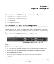
... device back to the factory defaults. 2-6 Physical Description v1.0, June 2009 Every RJ-45 port is capable of sensing the line speed and negotiating the operation duplex mode with the link partner automatically Figure 2-3 illustrates the NETGEAR GS724T Smart Switch front panel: System LEDs Reset PWR ® ProSafe 24 Port Gigabit Smart Switch 1 3 5 7 9 11 13 15 17...
... device back to the factory defaults. 2-6 Physical Description v1.0, June 2009 Every RJ-45 port is capable of sensing the line speed and negotiating the operation duplex mode with the link partner automatically Figure 2-3 illustrates the NETGEAR GS724T Smart Switch front panel: System LEDs Reset PWR ® ProSafe 24 Port Gigabit Smart Switch 1 3 5 7 9 11 13 15 17...

GS716Tv2/GS724Tv3 Hardware manual
Page 15
...NETGEAR, allowing fiber connections on the network. The module bay is a combo port, sharing a connection with the attached device, without requiring user intervention. When you can be used at any given time. If both copper and fiber port cannot be active at the same time. Factory Defaults Button The Smart Switch has a Factory Default... button so that you enable the Factory Default button, all settings, including the password, VLAN settings and port ...
...NETGEAR, allowing fiber connections on the network. The module bay is a combo port, sharing a connection with the attached device, without requiring user intervention. When you can be used at any given time. If both copper and fiber port cannot be active at the same time. Factory Defaults Button The Smart Switch has a Factory Default... button so that you enable the Factory Default button, all settings, including the password, VLAN settings and port ...

GS716Tv2/GS724Tv3 Hardware manual
Page 29
...-TX 1-2 10BASE-T 1-2 1U 1-3 8-pin 2-8 A AC Power 2-6, 2-7 AGM731F 2-9 AGM732F 2-9 AGM733 2-9 Applying AC Power 4-17 Attaching Switch to a Rack 4-15 Auto Sensing 1-2 Auto Uplink 2-8, 2-9 Auto-negotiating 1-2 Auto-sensing 2-8 B Back-pressure 1-3 Brackets 4-14 C Category...Devices to the Switch 4-16 Copper 1-1 Crossover 2-8 D Default IP Address 4-18 Default Reset Button 2-5, 2-6 Device Hardware Interfaces 2-8 Duplex Mode 2-8 E Example of Desktop Switching 3-11 F Factory Default Button 2-9 Factory Defaults 2-5 Fiber Connectivity 1-1 Flat Surface 4-14 Full-duplex 1-2 G GBIC 1-2, 2-9 Gigabit Ports 1-1 ...
...-TX 1-2 10BASE-T 1-2 1U 1-3 8-pin 2-8 A AC Power 2-6, 2-7 AGM731F 2-9 AGM732F 2-9 AGM733 2-9 Applying AC Power 4-17 Attaching Switch to a Rack 4-15 Auto Sensing 1-2 Auto Uplink 2-8, 2-9 Auto-negotiating 1-2 Auto-sensing 2-8 B Back-pressure 1-3 Brackets 4-14 C Category...Devices to the Switch 4-16 Copper 1-1 Crossover 2-8 D Default IP Address 4-18 Default Reset Button 2-5, 2-6 Device Hardware Interfaces 2-8 Duplex Mode 2-8 E Example of Desktop Switching 3-11 F Factory Default Button 2-9 Factory Defaults 2-5 Fiber Connectivity 1-1 Flat Surface 4-14 Full-duplex 1-2 G GBIC 1-2, 2-9 Gigabit Ports 1-1 ...

GS716Tv2/GS724Tv3 Software Admin Manual
Page 11
...and port information. • Chapter 3, "Configuring Switching Information" on page 3-1 describes how to manage and monitor the layer 2 switching features. • Chapter 4, "Configuring Quality of Service" on page 4-1 describes how to manage the GS716T/GS724T software ACLs, and how to ...within those procedures. About This Manual The NETGEAR® GS716Tv2 and GS724Tv3 Software Administration Manual describes how to configure and operate the Gigabit Smart Switch using its included software features by using its remaining factory default parameters. Audience The information in a network...
...and port information. • Chapter 3, "Configuring Switching Information" on page 3-1 describes how to manage and monitor the layer 2 switching features. • Chapter 4, "Configuring Quality of Service" on page 4-1 describes how to manage the GS716T/GS724T software ACLs, and how to ...within those procedures. About This Manual The NETGEAR® GS716Tv2 and GS724Tv3 Software Administration Manual describes how to configure and operate the Gigabit Smart Switch using its included software features by using its remaining factory default parameters. Audience The information in a network...

GS716Tv2/GS724Tv3 Software Admin Manual
Page 25
... (SNMP) Each of the standards-based management methods allows you use the Webbased interface to manage and monitor the system. Getting Started 1-9 v1.0, July 2009 Open a Web browser and enter the IP address of the switch in Figure 1-6 on to the Web ...Web browser address field. 2. Passwords are case sensitive. The factory default password is password. GS716Tv2 and GS724Tv3 Software Administration Manual Understanding the User Interfaces GS716T/GS724T software includes a set of comprehensive management functions for configuring and monitoring the system by using one of...
... (SNMP) Each of the standards-based management methods allows you use the Webbased interface to manage and monitor the system. Getting Started 1-9 v1.0, July 2009 Open a Web browser and enter the IP address of the switch in Figure 1-6 on to the Web ...Web browser address field. 2. Passwords are case sensitive. The factory default password is password. GS716Tv2 and GS724Tv3 Software Administration Manual Understanding the User Interfaces GS716T/GS724T software includes a set of comprehensive management functions for configuring and monitoring the system by using one of...

GS716Tv2/GS724Tv3 Software Admin Manual
Page 34
GS716Tv2 and GS724Tv3 Software Administration Manual Figure 2-1 Table 2-1. Enter the contact person for the switch's enterprise MIB. The base object ID for this switch. The universally assigned network address. System Description Fields Field System Name System Location ...to identify this switch. The factory default is blank. You may use to 31 alphanumeric characters. The serial number of the switch. 2-2 Configuring System Information v1.0, July 2009 You may use up to 31 alphanumeric characters. The factory default is blank. The factory default is blank. ...
GS716Tv2 and GS724Tv3 Software Administration Manual Figure 2-1 Table 2-1. Enter the contact person for the switch's enterprise MIB. The base object ID for this switch. The universally assigned network address. System Description Fields Field System Name System Location ...to identify this switch. The factory default is blank. You may use to 31 alphanumeric characters. The serial number of the switch. 2-2 Configuring System Information v1.0, July 2009 You may use up to 31 alphanumeric characters. The factory default is blank. The factory default is blank. ...

GS716Tv2/GS724Tv3 Software Admin Manual
Page 36
To access the switch over a network, you must start with IP information (IP address, subnet mask, and default gateway). The factory default value is 255.255.255.0. The factory default value is 192.168.0.239. Network Connectivity Fields Field IP Address Subnet Mask Default Gateway Management VLAN ID Description The IP address of the following options: • Dynamic IP...
To access the switch over a network, you must start with IP information (IP address, subnet mask, and default gateway). The factory default value is 255.255.255.0. The factory default value is 192.168.0.239. Network Connectivity Fields Field IP Address Subnet Mask Default Gateway Management VLAN ID Description The IP address of the following options: • Dynamic IP...

GS716Tv2/GS724Tv3 Software Admin Manual
Page 43
... Version Shows the format of the TFTP Server Address field The factory default is 1-4. 2. Specifies the priority of servers to view or modify information about the SNTP servers configured on your switch. The SNTP server is added, and is now reflected in ... complete the remaining fields as desired, and click Apply. The default is updated. 4. GS716Tv2 and GS724Tv3 Software Administration Manual Table 2-5. SNTP Server Configuration Fields Field Server Type Description Specifies the address type of the switch. 5. To access the SNTP Server Status page: Configuring System...
... Version Shows the format of the TFTP Server Address field The factory default is 1-4. 2. Specifies the priority of servers to view or modify information about the SNTP servers configured on your switch. The SNTP server is added, and is now reflected in ... complete the remaining fields as desired, and click Apply. The default is updated. 4. GS716Tv2 and GS724Tv3 Software Administration Manual Table 2-5. SNTP Server Configuration Fields Field Server Type Description Specifies the address type of the switch. 5. To access the SNTP Server Status page: Configuring System...

GS716Tv2/GS724Tv3 Software Admin Manual
Page 46
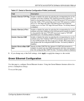
... 2-7. The factory default is disabled. The factory default is disabled. If First Fragment DoS prevention is enabled, the switch will drop packets that have a TCP header smaller than the configured Min TCP Hdr Size. GS716Tv2 and GS724Tv3 Software Administration Manual 1. The factory default is 20... bytes. Specify the Min TCP Hdr Size allowed. Enable or disable this configured Min TCP Hdr Size. The factory default is disabled. 2-14 v1.0, July 2009 Configuring System Information Click System Management ...
... 2-7. The factory default is disabled. The factory default is disabled. If First Fragment DoS prevention is enabled, the switch will drop packets that have a TCP header smaller than the configured Min TCP Hdr Size. GS716Tv2 and GS724Tv3 Software Administration Manual 1. The factory default is 20... bytes. Specify the Min TCP Hdr Size allowed. Enable or disable this configured Min TCP Hdr Size. The factory default is disabled. 2-14 v1.0, July 2009 Configuring System Information Click System Management ...
GS716Tv2/GS724Tv3 Software Admin Manual
Page 47
... by selecting the corresponding line on the pulldown entry field. Enabling ICMP DoS prevention causes the switch to configure Green Ethernet features. The factory default is disabled. 2. If you change any of Service ICMP Enable or disable this option by selecting... field. Using the Green Ethernet features allows for power consumption savings. The factory default is disabled. Green Ethernet Configuration Use this configured Max ICMP Pkt Size. GS716Tv2 and GS724Tv3 Software Administration Manual Table 2-7. Denial of Service Configuration Fields (continued) Field ...
... by selecting the corresponding line on the pulldown entry field. Enabling ICMP DoS prevention causes the switch to configure Green Ethernet features. The factory default is disabled. 2. If you change any of Service ICMP Enable or disable this option by selecting... field. Using the Green Ethernet features allows for power consumption savings. The factory default is disabled. Green Ethernet Configuration Use this configured Max ICMP Pkt Size. GS716Tv2 and GS724Tv3 Software Administration Manual Table 2-7. Denial of Service Configuration Fields (continued) Field ...

GS716Tv2/GS724Tv3 Software Admin Manual
Page 53
... enabled. Trap Flags Configuration Fields Field Description Authentication Link Up/Down Spanning Tree Enable or disable activation of the switch. The factory default is enabled. If you make any changes to this page: 1. To access this page, click Apply to send the updated ...button. Figure 2-11 and the following table show the fields that are available on the screen to the switch. The factory default is the configuration for SNMP v3. GS716Tv2 and GS724Tv3 Software Administration Manual Figure 2-11 The fields available on the Trap Flags page depends on the packages installed on...
... enabled. Trap Flags Configuration Fields Field Description Authentication Link Up/Down Spanning Tree Enable or disable activation of the switch. The factory default is enabled. If you make any changes to this page: 1. To access this page, click Apply to send the updated ...button. Figure 2-11 and the following table show the fields that are available on the screen to the switch. The factory default is the configuration for SNMP v3. GS716Tv2 and GS724Tv3 Software Administration Manual Figure 2-11 The fields available on the Trap Flags page depends on the packages installed on...

GS716Tv2/GS724Tv3 Software Admin Manual
Page 66
... Switching Information v1.0, July 2009 If you make to the Port Configuration page apply to 64 characters in the network. The port's maximum capability (full duplex and 1000 Mbps) will be set by the auto-negotiation process. The factory default is blank. GS716Tv2 and GS724Tv3 Software...that the port is a member of the following: • Enable: The port can be advertised. The string can participate in the network (default). • Disable: The port is a monitoring port. For additional information about port monitoring see "LAG Membership" on the system. For more ...
... Switching Information v1.0, July 2009 If you make to the Port Configuration page apply to 64 characters in the network. The port's maximum capability (full duplex and 1000 Mbps) will be set by the auto-negotiation process. The factory default is blank. GS716Tv2 and GS724Tv3 Software...that the port is a member of the following: • Enable: The port can be advertised. The string can participate in the network (default). • Disable: The port is a monitoring port. For additional information about port monitoring see "LAG Membership" on the system. For more ...

GS716Tv2/GS724Tv3 Software Admin Manual
Page 67
...factory default... the screen to manage in low power mode (nominal power). • Disable: The port is 1518. Configuring Switching Information 3-3 v1...specified interface. Displays the physical address of the switch. 3. The default maximum frame size is administratively down and does not... participate in Green Ethernet mode. Use the menu to select the port's Green Ethernet mode, which can be one of time, and wakes up to select the port's Green Ethernet mode, which corresponds to All, this port. GS716Tv2 and GS724Tv3...
...factory default... the screen to manage in low power mode (nominal power). • Disable: The port is 1518. Configuring Switching Information 3-3 v1...specified interface. Displays the physical address of the switch. 3. The default maximum frame size is administratively down and does not... participate in Green Ethernet mode. Use the menu to select the port's Green Ethernet mode, which can be one of time, and wakes up to select the port's Green Ethernet mode, which corresponds to All, this port. GS716Tv2 and GS724Tv3...
GS716Tv2/GS724Tv3 Software Admin Manual
Page 68
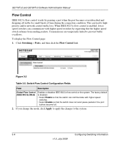
This can lead to prevent buffer overflows. To display the Flow Control page: 1. The factory default is enabled, lower speed switches can communicate with higher speed switches by pausing a port when the port becomes oversubscribed and dropping all traffic for small bursts of time ...3x flow control is disabled. • Select Enable so that the switch can communicate with higher speed switches. • Select Disable so that the higher speed switch refrains from sending packets. GS716Tv2 and GS724Tv3 Software Administration Manual Flow Control IEEE 802.3x flow control works by ...
This can lead to prevent buffer overflows. To display the Flow Control page: 1. The factory default is enabled, lower speed switches can communicate with higher speed switches by pausing a port when the port becomes oversubscribed and dropping all traffic for small bursts of time ...3x flow control is disabled. • Select Enable so that the switch can communicate with higher speed switches. • Select Disable so that the higher speed switch refrains from sending packets. GS716Tv2 and GS724Tv3 Software Administration Manual Flow Control IEEE 802.3x flow control works by ...

GS716Tv2/GS724Tv3 Software Admin Manual
Page 70
... the links that are actively participating members of up to have a trap sent when link status changes. The factory default is static, it does not transmit or process received LAGPDUs, i.e., the member ports do not transmit LAGPDUs and...it may enter any string of this Port Channel. When the LAG is Enable. The default is Up or Down. 3-6 Configuring Switching Information v1.0, July 2009 LAG (Port Channel) Configuration Fields Field LAG Name Description LAG ID...is Static. It can be attached to the LAG. GS716Tv2 and GS724Tv3 Software Administration Manual Figure 3-3 Table 3-3.
... the links that are actively participating members of up to have a trap sent when link status changes. The factory default is static, it does not transmit or process received LAGPDUs, i.e., the member ports do not transmit LAGPDUs and...it may enter any string of this Port Channel. When the LAG is Enable. The default is Up or Down. 3-6 Configuring Switching Information v1.0, July 2009 LAG (Port Channel) Configuration Fields Field LAG Name Description LAG ID...is Static. It can be attached to the LAG. GS716Tv2 and GS724Tv3 Software Administration Manual Figure 3-3 Table 3-3.
GS716Tv2/GS724Tv3 Software Admin Manual
Page 79
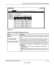
... want assigned to display or configure data. GS716Tv2 and GS724Tv3 Software Administration Manual Figure 3-10 Table 3-9. Specify the ... select, VLAN tagged frames will be forwarded in accordance with the IEEE 802.1Q VLAN standard. The factory default is Admit All. • VLAN Only: The port will discard any untagged or priority tagged frames... it receives. • Admit All: Untagged and priority tagged frames received on this port. The factory default is 1. Port VLAN ID Configuration Fields Field Interface Port VLAN ID (PVID) Acceptable Frame Types Description ...
... want assigned to display or configure data. GS716Tv2 and GS724Tv3 Software Administration Manual Figure 3-10 Table 3-9. Specify the ... select, VLAN tagged frames will be forwarded in accordance with the IEEE 802.1Q VLAN standard. The factory default is Admit All. • VLAN Only: The port will discard any untagged or priority tagged frames... it receives. • Admit All: Untagged and priority tagged frames received on this port. The factory default is 1. Port VLAN ID Configuration Fields Field Interface Port VLAN ID (PVID) Acceptable Frame Types Description ...

GS716Tv2/GS724Tv3 Software Admin Manual
Page 80
GS716Tv2 and GS724Tv3 Software Administration Manual Table 3-9. Configuring Spanning Tree Protocol The Spanning Tree Protocol (STP) provides a tree topology for the port that received this frame. • Disable: ....0, July 2009 Configuring Switching Information MSTP is disable. STP also provides one path between end stations, avoiding and eliminating loops. These features are 0-7. 2. In an untagged frame, the VLAN is the Port VLAN ID specified for any changes to this port is the rapid transitioning of bridges. The factory default is compatible to...
GS716Tv2 and GS724Tv3 Software Administration Manual Table 3-9. Configuring Spanning Tree Protocol The Spanning Tree Protocol (STP) provides a tree topology for the port that received this frame. • Disable: ....0, July 2009 Configuring Switching Information MSTP is disable. STP also provides one path between end stations, avoiding and eliminating loops. These features are 0-7. 2. In an untagged frame, the VLAN is the Port VLAN ID specified for any changes to this port is the rapid transitioning of bridges. The factory default is compatible to...


