
GS716Tv2/GS724Tv3 Hardware manual
Page 9
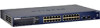
Reset PWR ® ProSafe 24 Port Gigabit Smart Switch 1 3 5 7 9 11 13 15 17 19 21 23 LINK/ACT SPD Green (1000M) Yellow (100M) FDX 2 4 6 8 10 12 14 16 18 20 22 24 LINK/ACT ... ACT MODEL GS724T Auto™ Uplink Factory Defaults Figure 1-1 Introduction 1-3 v1.0, June 2009 Package Contents Figure 1-1 shows the package contents of the NETGEAR GS716T and GS724T Series Smart Switch. GS716T/GS724T Hardware Installation Guide • Automatic address learning function to minimize packet loss/frame drops. • Half-duplex back-pressure control. •...
Reset PWR ® ProSafe 24 Port Gigabit Smart Switch 1 3 5 7 9 11 13 15 17 19 21 23 LINK/ACT SPD Green (1000M) Yellow (100M) FDX 2 4 6 8 10 12 14 16 18 20 22 24 LINK/ACT ... ACT MODEL GS724T Auto™ Uplink Factory Defaults Figure 1-1 Introduction 1-3 v1.0, June 2009 Package Contents Figure 1-1 shows the package contents of the NETGEAR GS716T and GS724T Series Smart Switch. GS716T/GS724T Hardware Installation Guide • Automatic address learning function to minimize packet loss/frame drops. • Half-duplex back-pressure control. •...
GS716Tv2/GS724Tv3 Hardware manual
Page 11
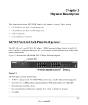
...capable of sensing the line speed and negotiating the operation duplex mode with the link partner automatically Figure 2-1 illustrates the NETGEAR GS716T Smart Switch front panel: System LEDs Reset PWR ® ProSafe 16 Port Gigabit Smart Switch 1 3 5 7 9 11 13 15 LINK/ACT SPD Green (1000M) Yellow (100M) FDX 2 4 6...45 connectors for 10/100/1000 Mbps auto sensing Gigabit Ethernet switching ports. • Two SFP slots for SFP modules supporting 1000 (1000BASE-SX/LX)/100 Mbps SFP. • Reset button to restart the device. • Recessed default reset button to restore the device back to the ...
...capable of sensing the line speed and negotiating the operation duplex mode with the link partner automatically Figure 2-1 illustrates the NETGEAR GS716T Smart Switch front panel: System LEDs Reset PWR ® ProSafe 16 Port Gigabit Smart Switch 1 3 5 7 9 11 13 15 LINK/ACT SPD Green (1000M) Yellow (100M) FDX 2 4 6...45 connectors for 10/100/1000 Mbps auto sensing Gigabit Ethernet switching ports. • Two SFP slots for SFP modules supporting 1000 (1000BASE-SX/LX)/100 Mbps SFP. • Reset button to restart the device. • Recessed default reset button to restore the device back to the ...

GS716Tv2/GS724Tv3 Hardware manual
Page 12
... of sensing the line speed and negotiating the operation duplex mode with the link partner automatically Figure 2-3 illustrates the NETGEAR GS724T Smart Switch front panel: System LEDs Reset PWR ® ProSafe 24 Port Gigabit Smart Switch 1 3 5 7 9 11 13 15 17 19 21 23 LINK/ACT SPD Green (1000M) Yellow (100M...System LEDs Figure 2-2 illustrates the NETGEAR GS716T Smart Switch back panel: 100-240V ~ 50-60Hz Figure 2-2 RS-232 Power Connector The back panel contains the following : • 24 RJ-45 connectors for 10/100/1000 Mbps auto-sensing Gigabit Ethernet switching ports. • Two slots...
... of sensing the line speed and negotiating the operation duplex mode with the link partner automatically Figure 2-3 illustrates the NETGEAR GS724T Smart Switch front panel: System LEDs Reset PWR ® ProSafe 24 Port Gigabit Smart Switch 1 3 5 7 9 11 13 15 17 19 21 23 LINK/ACT SPD Green (1000M) Yellow (100M...System LEDs Figure 2-2 illustrates the NETGEAR GS716T Smart Switch back panel: 100-240V ~ 50-60Hz Figure 2-2 RS-232 Power Connector The back panel contains the following : • 24 RJ-45 connectors for 10/100/1000 Mbps auto-sensing Gigabit Ethernet switching ports. • Two slots...

GS716Tv2/GS724Tv3 Hardware manual
Page 24
...in this section. Configuration If problems occur after altering the network configuration, restore the original connections and determine the problem by resetting the switch. To reset the switch, remove the AC power from any networked device to any other physical aspects of North America, please refer to the ...Cards Ensure the network adapter cards installed in working condition and the software driver has been installed. In North America, call 1-888-NETGEAR. If you are in the PCs are outside of the installation do not resolve the problem, refer to the support information card...
...in this section. Configuration If problems occur after altering the network configuration, restore the original connections and determine the problem by resetting the switch. To reset the switch, remove the AC power from any networked device to any other physical aspects of North America, please refer to the ...Cards Ensure the network adapter cards installed in working condition and the software driver has been installed. In North America, call 1-888-NETGEAR. If you are in the PCs are outside of the installation do not resolve the problem, refer to the support information card...

GS716Tv2/GS724Tv3 Hardware manual
Page 29
...2-6 100BASE-TX 1-2 10BASE-T 1-2 1U 1-3 8-pin 2-8 A AC Power 2-6, 2-7 AGM731F 2-9 AGM732F 2-9 AGM733 2-9 Applying AC Power 4-17 Attaching Switch to a Rack 4-15 Auto Sensing 1-2 Auto Uplink 2-8, 2-9 Auto-negotiating 1-2 Auto-sensing 2-8 B Back-pressure 1-3 Brackets 4-14 C Category 5 ... the Switch 4-16 Copper 1-1 Crossover 2-8 D Default IP Address 4-18 Default Reset Button 2-5, 2-6 Device Hardware Interfaces 2-8 Duplex Mode 2-8 E Example of Desktop Switching 3-11 F Factory Default Button 2-9 Factory Defaults 2-5 Fiber Connectivity 1-1 Flat Surface 4-14 Full-duplex 1-2 G GBIC 1-2, 2-9 Gigabit Ports ...
...2-6 100BASE-TX 1-2 10BASE-T 1-2 1U 1-3 8-pin 2-8 A AC Power 2-6, 2-7 AGM731F 2-9 AGM732F 2-9 AGM733 2-9 Applying AC Power 4-17 Attaching Switch to a Rack 4-15 Auto Sensing 1-2 Auto Uplink 2-8, 2-9 Auto-negotiating 1-2 Auto-sensing 2-8 B Back-pressure 1-3 Brackets 4-14 C Category 5 ... the Switch 4-16 Copper 1-1 Crossover 2-8 D Default IP Address 4-18 Default Reset Button 2-5, 2-6 Device Hardware Interfaces 2-8 Duplex Mode 2-8 E Example of Desktop Switching 3-11 F Factory Default Button 2-9 Factory Defaults 2-5 Fiber Connectivity 1-1 Flat Surface 4-14 Full-duplex 1-2 G GBIC 1-2, 2-9 Gigabit Ports ...

GS716Tv2/GS724Tv3 Hardware manual
Page 30
...Flow Control 1-3 Phillips Screwdriver 4-14 Index-28 Port LEDs 2-7 Power cord 1-4 Preparing the Site 4-13 R Rack 4-14 Rack-mount Kit 1-4, 4-14 Reset Button 2-5, 2-6 RJ-45 1-2 RJ-45 Ports 2-8 Rubber footpads 1-4, 4-14 S SFP GBIC Module 2-9 SFP LINK/ACT LED 2-8 SFP Module Bay ...4-17 Site Requirements 4-13 Small Form-factor Pluggable (SFP) 1-2 Smart Switch Resource CD 1-4 Smart Wizard Discovery 1-2 Straight-through 2-8 Support Information Card 1-4 System LEDs 2-8 T Temperature 4-14 Traffic Control 1-1 Troubleshooting Chart A-19 U ...
...Flow Control 1-3 Phillips Screwdriver 4-14 Index-28 Port LEDs 2-7 Power cord 1-4 Preparing the Site 4-13 R Rack 4-14 Rack-mount Kit 1-4, 4-14 Reset Button 2-5, 2-6 RJ-45 1-2 RJ-45 Ports 2-8 Rubber footpads 1-4, 4-14 S SFP GBIC Module 2-9 SFP LINK/ACT LED 2-8 SFP Module Bay ...4-17 Site Requirements 4-13 Small Form-factor Pluggable (SFP) 1-2 Smart Switch Resource CD 1-4 Smart Wizard Discovery 1-2 Straight-through 2-8 Support Information Card 1-4 System LEDs 2-8 T Temperature 4-14 Traffic Control 1-1 Troubleshooting Chart A-19 U ...

GS716Tv2/GS724Tv3 Software Admin Manual
Page 9
... 7 Maintenance Reset ...7-1 Rebooting the Switch 7-1 Reset Configuration to Defaults 7-2 Upload File From Switch 7-3 Uploading Files ...7-5 Download File To Switch 7-5 TFTP File Download 7-6 HTTP File Download 7-8 File Management ...7-10 Dual Image Configuration 7-10 Viewing the Dual Image Status 7-12 Troubleshooting ...7-13 Ping ...7-13 TraceRoute ...7-14 Appendix A Hardware Specifications and Default Values GS7xxT Gigabit Smart Switch Specifications A-1 GS7xxTR Gigabit Smart Switch Features...
... 7 Maintenance Reset ...7-1 Rebooting the Switch 7-1 Reset Configuration to Defaults 7-2 Upload File From Switch 7-3 Uploading Files ...7-5 Download File To Switch 7-5 TFTP File Download 7-6 HTTP File Download 7-8 File Management ...7-10 Dual Image Configuration 7-10 Viewing the Dual Image Status 7-12 Troubleshooting ...7-13 Ping ...7-13 TraceRoute ...7-14 Appendix A Hardware Specifications and Default Values GS7xxT Gigabit Smart Switch Specifications A-1 GS7xxTR Gigabit Smart Switch Features...

GS716Tv2/GS724Tv3 Software Admin Manual
Page 28
.... Configuration changes take effect immediately. Common Command Buttons Button Add Function Click Add to update the switch with the latest information from drop down arrow symbol and, if there is a subfolder, the... folder expands to cancel the configuration on the screen and reset the data on a screen. To remove a configured item, select it becomes preceded by a down ... or subfolder, it and click Delete. GS716Tv2 and GS724Tv3 Software Administration Manual subfolder, and HTML page in the navigation menu. Each page contains access to the...
.... Configuration changes take effect immediately. Common Command Buttons Button Add Function Click Add to update the switch with the latest information from drop down arrow symbol and, if there is a subfolder, the... folder expands to cancel the configuration on the screen and reset the data on a screen. To remove a configured item, select it becomes preceded by a down ... or subfolder, it and click Delete. GS716Tv2 and GS724Tv3 Software Administration Manual subfolder, and HTML page in the navigation menu. Each page contains access to the...

GS716Tv2/GS724Tv3 Software Admin Manual
Page 37
...(SNTP). SNTP assures accurate network device clock time synchronization up to cancel the configuration on the screen and reset the data on the device are polled for the server time. The device receives time from stratum 1 ... type. Time synchronization is the most secure method. If this Configuring System Information 2-5 v1.0, July 2009 GS716Tv2 and GS724Tv3 Software Administration Manual 3. The following time levels: • T1: Time at which the original request was sent by... poll Unicast server types for synchronization information. If you change any of the switch. 4.
...(SNTP). SNTP assures accurate network device clock time synchronization up to cancel the configuration on the screen and reset the data on the device are polled for the server time. The device receives time from stratum 1 ... type. Time synchronization is the most secure method. If this Configuring System Information 2-5 v1.0, July 2009 GS716Tv2 and GS724Tv3 Software Administration Manual 3. The following time levels: • T1: Time at which the original request was sent by... poll Unicast server types for synchronization information. If you change any of the switch. 4.

GS716Tv2/GS724Tv3 Software Admin Manual
Page 40
...the screen to cancel the configuration on the screen and reset the data on Coordinated Universal Time (UTC), which the switch is UTC 00:00. 5. Click Refresh to view...of the box in hours, minutes and seconds since the last reboot. Click System Management Time SNTP Global Configuration in which is the same as Greenwich Mean ....0, July 2009 Configuring System Information GS716Tv2 and GS724Tv3 Software Administration Manual Table 2-3. Time Zone configures a time zone specifying the time difference from the switch. 6. This may not be the time zone...
...the screen to cancel the configuration on the screen and reset the data on Coordinated Universal Time (UTC), which the switch is UTC 00:00. 5. Click Refresh to view...of the box in hours, minutes and seconds since the last reboot. Click System Management Time SNTP Global Configuration in which is the same as Greenwich Mean ....0, July 2009 Configuring System Information GS716Tv2 and GS724Tv3 Software Administration Manual Table 2-3. Time Zone configures a time zone specifying the time difference from the switch. 6. This may not be the time zone...

GS716Tv2/GS724Tv3 Software Admin Manual
Page 42
GS716Tv2 and GS724Tv3 Software Administration Manual Table 2-4. Specifies the number of the switch. 4. Click Cancel to cancel the configuration on the screen and reset the data on the screen to the switch. If you change any of unicast server entries that can be configured on ...configured for adding and modifying Simple Network Time Protocol SNTP servers. To display the SNTP Server Configuration page: 1. Click System Management Time SNTP Server Configuration in the navigation tree. Configuration changes take effect immediately. Figure 2-5 2-10 v1.0, July...
GS716Tv2 and GS724Tv3 Software Administration Manual Table 2-4. Specifies the number of the switch. 4. Click Cancel to cancel the configuration on the screen and reset the data on the screen to the switch. If you change any of unicast server entries that can be configured on ...configured for adding and modifying Simple Network Time Protocol SNTP servers. To display the SNTP Server Configuration page: 1. Click System Management Time SNTP Server Configuration in the navigation tree. Configuration changes take effect immediately. Figure 2-5 2-10 v1.0, July...

GS716Tv2/GS724Tv3 Software Admin Manual
Page 43
...Delete. Click Cancel to cancel the configuration on the screen and reset the data on the screen to the switch. To access the SNTP Server Status page: Configuring System Information v1.0, July 2009 2-11 GS716Tv2 and GS724Tv3 Software Administration Manual Table 2-5. SNTP Server Configuration Fields Field Server... Status page displays status information about , or select Add to remove from 1-65535. Specifies the priority of the settings on your switch. The SNTP server is added, and is now reflected in determining the sequence of the SNTP server. The entry is removed, ...
...Delete. Click Cancel to cancel the configuration on the screen and reset the data on the screen to the switch. To access the SNTP Server Status page: Configuring System Information v1.0, July 2009 2-11 GS716Tv2 and GS724Tv3 Software Administration Manual Table 2-5. SNTP Server Configuration Fields Field Server... Status page displays status information about , or select Add to remove from 1-65535. Specifies the priority of the settings on your switch. The SNTP server is added, and is now reflected in determining the sequence of the SNTP server. The entry is removed, ...

GS716Tv2/GS724Tv3 Software Admin Manual
Page 51
...Trap Configuration This page displays an entry for every active Trap Receiver. GS716Tv2 and GS724Tv3 Software Administration Manual Table 2-10. To access this device. Figure 2-10 Table 2-11. Uses SNMP v2 to send traps to the switch. Reset the data on the screen. Uses SNMP v1 to send traps to the ...latest value of the switch. Sends the updated configuration to be used by the receiver from this page, click System ...
...Trap Configuration This page displays an entry for every active Trap Receiver. GS716Tv2 and GS724Tv3 Software Administration Manual Table 2-10. To access this device. Figure 2-10 Table 2-11. Uses SNMP v2 to send traps to the switch. Reset the data on the screen. Uses SNMP v1 to send traps to the ...latest value of the switch. Sends the updated configuration to be used by the receiver from this page, click System ...

GS716Tv2/GS724Tv3 Software Admin Manual
Page 52
...Community String Status Description Enter the community string for the SNMP trap packet to be up to 16 characters and is written to the trap manager. Select the receiver's status from the pulldown menu: • Enable - Cancel the configuration on the screen to any enabled SNMP Trap Receivers..., and a message is case sensitive. When the condition identified by an active trap is encountered by the switch, a trap message is sent to the latest value of the switch. Reset the data on the screen. GS716Tv2 and GS724Tv3 Software Administration Manual Table 2-11.
...Community String Status Description Enter the community string for the SNMP trap packet to be up to 16 characters and is written to the trap manager. Select the receiver's status from the pulldown menu: • Enable - Cancel the configuration on the screen to any enabled SNMP Trap Receivers..., and a message is case sensitive. When the condition identified by an active trap is encountered by the switch, a trap message is sent to the latest value of the switch. Reset the data on the screen. GS716Tv2 and GS724Tv3 Software Administration Manual Table 2-11.

GS716Tv2/GS724Tv3 Software Admin Manual
Page 53
... the corresponding button. SNMP v3 User Configuration This is enabled. The factory default is the configuration for SNMP v3. GS716Tv2 and GS724Tv3 Software Administration Manual Figure 2-11 The fields available on the Trap Flags page depends on the packages installed on a system with all...13. Click System SNMP SNMP V3 User Configuration in the navigation menu. Enable or disable activation of the switch. Figure 2-11 and the following table show the fields that are available on your system. Click Cancel to cancel the configuration on the...
... the corresponding button. SNMP v3 User Configuration This is enabled. The factory default is the configuration for SNMP v3. GS716Tv2 and GS724Tv3 Software Administration Manual Figure 2-11 The fields available on the Trap Flags page depends on the packages installed on a system with all...13. Click System SNMP SNMP V3 User Configuration in the navigation menu. Enable or disable activation of the switch. Figure 2-11 and the following table show the fields that are available on your system. Click Cancel to cancel the configuration on the...

GS716Tv2/GS724Tv3 Software Admin Manual
Page 54
... None, MD5, or SHA. The Apply check box must therefore specify a password. GS716Tv2 and GS724Tv3 Software Administration Manual Figure 2-12 Table 2-14. The user will be checked in the Encryption Key...Protocol setting for the user account. Valid keys are 0 to the latest value of the switch. 2-22 v1.0, July 2009 Configuring System Information Specify the SNMPv3 Authentication Protocol setting for the .... • MD5 or SHA - Click Cancel to cancel the configuration on the screen and reset the data on the screen to 15 characters long. If you must be unable to change ...
... None, MD5, or SHA. The Apply check box must therefore specify a password. GS716Tv2 and GS724Tv3 Software Administration Manual Figure 2-12 Table 2-14. The user will be checked in the Encryption Key...Protocol setting for the user account. Valid keys are 0 to the latest value of the switch. 2-22 v1.0, July 2009 Configuring System Information Specify the SNMPv3 Authentication Protocol setting for the .... • MD5 or SHA - Click Cancel to cancel the configuration on the screen and reset the data on the screen to 15 characters long. If you must be unable to change ...

GS716Tv2/GS724Tv3 Software Admin Manual
Page 67
...Indicates whether the Link is administratively down . The default maximum frame size is configured to manage in Green Ethernet mode. The ifIndex of the following : Enable: Specifies that the system...value of the specified interface. GS716Tv2 and GS724Tv3 Software Administration Manual Table 3-1. Click Cancel to cancel the configuration on the screen and reset the data on the screen to All...8226; Disable: The port is administratively down and does not participate in SNMP. Configuring Switching Information 3-3 v1.0, July 2009 Display the bit offset value which can be one ...
...Indicates whether the Link is administratively down . The default maximum frame size is configured to manage in Green Ethernet mode. The ifIndex of the following : Enable: Specifies that the system...value of the specified interface. GS716Tv2 and GS724Tv3 Software Administration Manual Table 3-1. Click Cancel to cancel the configuration on the screen and reset the data on the screen to All...8226; Disable: The port is administratively down and does not participate in SNMP. Configuring Switching Information 3-3 v1.0, July 2009 Display the bit offset value which can be one ...

GS716Tv2/GS724Tv3 Software Admin Manual
Page 71
... Basic LAG Membership in the default VLAN. 4. GS716Tv2 and GS724Tv3 Software Administration Manual 2. Enter the name you make any string of the switch. 5. Configuration changes take effect immediately. Click Add to cancel the configuration on the screen and reset the data on this screen. 3. LAG Membership Use the LAG Membership page...
... Basic LAG Membership in the default VLAN. 4. GS716Tv2 and GS724Tv3 Software Administration Manual 2. Enter the name you make any string of the switch. 5. Configuration changes take effect immediately. Click Add to cancel the configuration on the screen and reset the data on this screen. 3. LAG Membership Use the LAG Membership page...

GS716Tv2/GS724Tv3 Software Admin Manual
Page 72
...display the LACP Configuration page: 1. Click Refresh to this LAG. Figure 3-5 Table 3-5. You can change the value of the switch. 3. GS716Tv2 and GS724Tv3 Software Administration Manual Table 3-4. Configuration changes take effect immediately. LAG Membership Fields (continued) Field Port Selection Table Current Members Description ... to the devices at the other ends of the links on the screen to cancel the configuration on the screen and reset the data on which link aggregation is 32768. 2. If you make any changes to reload the page and display the most...
...display the LACP Configuration page: 1. Click Refresh to this LAG. Figure 3-5 Table 3-5. You can change the value of the switch. 3. GS716Tv2 and GS724Tv3 Software Administration Manual Table 3-4. Configuration changes take effect immediately. LAG Membership Fields (continued) Field Port Selection Table Current Members Description ... to the devices at the other ends of the links on the screen to cancel the configuration on the screen and reset the data on which link aggregation is 32768. 2. If you make any changes to reload the page and display the most...

GS716Tv2/GS724Tv3 Software Admin Manual
Page 73
... to cancel the configuration on the screen and reset the data on the screen to the switch. Click Cancel to cancel the configuration on the screen and reset the data on the screen to be displayed or configured. LACP Priority Specifies port priority value. GS716Tv2 and GS724Tv3 Software Administration Manual 3. If you make any...
... to cancel the configuration on the screen and reset the data on the screen to the switch. Click Cancel to cancel the configuration on the screen and reset the data on the screen to be displayed or configured. LACP Priority Specifies port priority value. GS716Tv2 and GS724Tv3 Software Administration Manual 3. If you make any...


